Table of Contents
Advertisement
Quick Links
Installation and Assembly Manual:
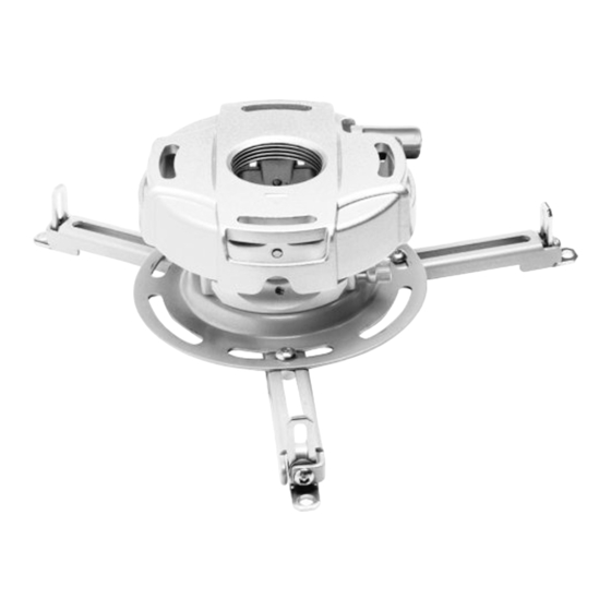
PRG Precision Gear Projector Mount
Models: PRG-1, PRG-1S, PRG-1W
Features:
TM
• ImageLock
alignment prevents picture sag or drift
• Exclusive aluminum track quick release
2300 White Oak Circle • Aurora, Il 60502 • (800) 865-2112 • Fax: (800)359-6500 • www.peerlessmounts.com
This product is intended for use with UL
U L
Listed products and must be installed by a
C
US
©
qualifi ed professional installer.
Maximum UL Load Capacity:
50 lb (22.7 kg)
ISSUED: 08-15-07 SHEET #: 055-9491-7 06-11-11
Advertisement
Table of Contents

Related Manuals for peerless-AV PRG-1


Summary of Contents for peerless-AV PRG-1
- Page 1 Installation and Assembly Manual: PRG Precision Gear Projector Mount Models: PRG-1, PRG-1S, PRG-1W This product is intended for use with UL Listed products and must be installed by a © qualifi ed professional installer. Features: Maximum UL Load Capacity: • ImageLock alignment prevents picture sag or drift 50 lb (22.7 kg) •...
-
Page 2: Table Of Contents
NOTE: Read entire instruction sheet before you start installation and assembly. WARNING • Do not begin to install your Peerless product until you have read and understood the instructions and warnings contained in this Installation Sheet. If you have any questions regarding any of the instructions or warnings, please call Peerless customer care at 1-800-865-2112. -
Page 3: Parts List
Before you start check the parts list to insure all of the parts shown are included. Parts List PRG-1 PRG-1S PRG-1W Description Qty. Part # Part # Part # A projector mount assembly 055-1968 055-4968 055-2968 B 4 mm security allen wrench 560-9646 560-9646 560-9646... -
Page 4: Installation To Extension Columns / Ceiling Plate
Installation to Extension Column / Ceiling Plate NOTE: Refer to accompanying instructions with ceiling plates (sold separately) for installing these models to ceiling. Screw projector mount assembly (A) onto extension column as shown in fi gure 1.1. Tighten swivel stop screw against extension column, fl... -
Page 5: Installation To Wood Joist Ceilings
Installation To Wood Joist Ceilings WARNING • Installer must verify that the supporting surface will safely support the combined load of the equipment and all attached hardware and components. • Tighten wood screws so that projector mount assembly is fi rmly attached, but do not overtighten. Overtightening can damage the screws, greatly reducing their holding power. -
Page 6: Installation To Concrete Ceilings
Installation to Concrete Ceilings WARNING • Concrete must be 2000 psi density minimum. Lighter density concrete may not hold concrete anchor. • Make sure that the supporting surface will safely support the combined load of the equipment and all attached hardware and components. -
Page 7: Installation To Threaded Rods
Installation to Threaded Rod (Not evaluated by UL - Professional installation only) Thread two 1/4-20 hex thin nylon-insert locknuts (not included) on two 1/4-20 threaded rods (not included) to the desired height of projector mount assembly. Attach projector mount assembly (A) to the two 1/4-20 threaded rods using two 1/4-20 hex thin nylon-insert locknuts as shown in fi... -
Page 8: Attaching Adapter Plate To Projector
Attaching Adapter Plate to Projector CAUTION • It is the responsibility of the installer to ensure that SHOULDER the projector is properly ventilated. NOTCH INDICATES FRONT OF PROJECTOR Installing Dedicated PAP Series DEDICATED Adapter Plate (sold separately) ADAPTER PLATE (SOLD SEPARATELY) NOTE: The projector dedicated adapter plate you are installing may differ in appearance from the sample illustrated in fi... -
Page 9: Attaching Adapter Plate To Projector Mount
Attaching Adapter Plate to Projector Mount WARNING • Do not lift more weight than you can handle. Use additional man power or mechanical lifting equipment to safely handle placement of the projector. Slide connection block (I) with projector into projector mount assembly (A) as shown. Tighten captive screw to secure projector to projector mount assembly (A). -
Page 10: Cable Management
Cable Management fi g. 8.1 CABLES WITH COMBINATION NOTE: INNER DIAMETER OF To make an opening to route cables through OF VGA CONNECTOR EXTENSION COLUMN MAY NOT projector mount assembly, adjust projector mount AND RCA PLUGS ALLOW PASSAGE FOR ALL assembly to full upward tilt position by turning CONNECTOR TYPES. -
Page 11: Projector Alignment
Projector Alignment To adjust yaw (swivel) for threaded rod mounting applications: Loosen locknuts on threaded rods (step 5), until projector mount can be rotated. Rotate mount to desired position and retighten locknuts. To adjust yaw (swivel) for extension column applications: Loosen screw on projector mount assembly (A) indicated below until projector mount can be rotated. -
Page 12: Accessories
PRG Series Projector Mount Accessories 12 of 13 ISSUED: 08-15-07 SHEET #: 055-9491-7 06-11-11 Visit the Peerless Web Site at www.peerlessmounts.com For customer care call 1-800-865-2112 or 708-865-8870. -
Page 13: Accessories
ISSUED: 08-15-07 SHEET #: 055-9491-7 06-11-11 For customer care call 1-800-865-2112 or 708-865-8870. Visit the Peerless Web Site at www.peerlessmounts.com © 2008, Peerless Industries, Inc. All rights reserved. All other brand and product names are trademarks or registered trademarks of their respective owners.
Need help?
Do you have a question about the PRG-1 and is the answer not in the manual?
Questions and answers