Table of Contents
Advertisement
SEARS
owner's
manual
Model No.
C950-60901-0
CAUTION:
Read And Follow
All Safety Rules
And Instructions
Before Operating
This Equipment.
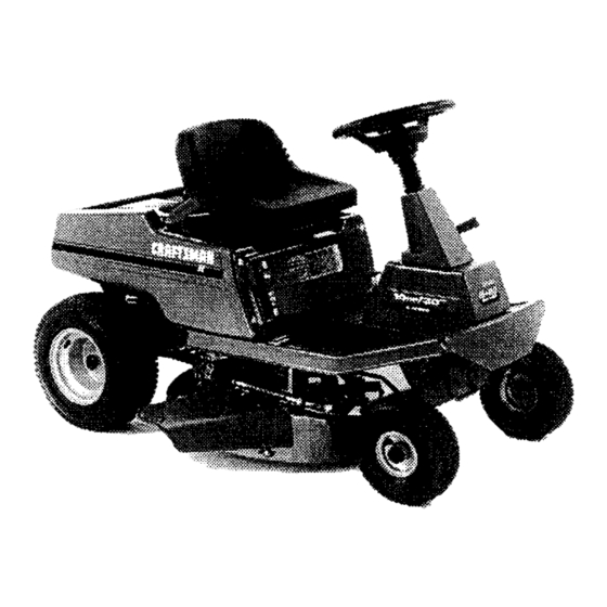
10 HP. ELECTRIC START
30" MOWER / MULCHER
5 SPEED
REAR ENGINE RIDER
• Assembly
• Operation
• Customer Responsibilities
• Service And Adjustment
F-99635
Sears Canada Inc., Toronto, Ontario M5B 2B8
Printed inU.SA
Advertisement
Table of Contents

Related Manuals for Craftsman C950-60901-0


Summary of Contents for Craftsman C950-60901-0
- Page 1 SEARS owner's manual Model No. C950-60901-0 10 HP. ELECTRIC START CAUTION: 30" MOWER / MULCHER Read And Follow 5 SPEED All Safety Rules And Instructions REAR ENGINE RIDER Before Operating This Equipment. • Assembly • Operation • Customer Responsibilities • Service And Adjustment F-99635 Sears Canada Inc., Toronto, Ontario M5B 2B8 Printed inU.SA...
- Page 2 Owner's Manual. In Home Service. Warranty service is available by returning the Craftsman snow blower to the nearest Sears Service Centre/Department in Canada. This war- ranty applies only white this product is in use in Canada.
-
Page 3: Maintenance Chart
Congratulations on your purchase of a Sears Rider. It has been NOTE: This unit is equipped with an intemal combustion engine and designed, engineered and manufactured to give you the best must not be used on or near any unimproved forest-covered, possible dependability and performance. - Page 4 OWNER'S INFORMATION SAFETY RULES Safe Operation Practices for Ride-on Mowers WARNING: This cutting machine is capable of amputating hands and feet and throwing objects, Failure to observe the following safety instructions could result in serious injury or death. General operation Read, understand and follow all instructions in the InstructionBook, on the machine, the engine and with any attachments before starting.
- Page 5 OWNER'S INFORMATION Never carry children or any passengers, even with the blades off. They may fall off and be seriously injured or interfere with the safe operation of the machine. Never allow children to operate the machine. Instruct children in the potential dangers of the machine. Use extra care when approaching blind corners, shrubs, trees or other objects that may obscure vision.
- Page 6 ACCESSORIES AND ATTACHMENTS ACCESSORIES AND A'I-rACHMENTS These accessories and attachments were available when the unit was purchased. They are also available at most Sears retail outlets, catalog and service centers. Most Sears stores can order these items for you when you provide the model number of your riding mower. MAINTENANCE ENGINE ENGINE OIL...
- Page 7 ASSEMBLY Phillips screwdriver PREPARATION Low Tire pressure gauge The unit is completely assembled except for the items shown in Knife Figure 1. These items are in the carton along with a parts bag. The Socket Set (Optional) parts bag contains the fasteners needed to complete the assembly of the unit.
- Page 8 ASSEMBLY MAINTENANCE FREE BA'n'ERY Install the battery. See "How To Install The Battery" in the Customer Responsibilities section. IMPORTANT: Before you attach the battery cables to the battery, check the battery date. The battery date tells if the HOW TO INSTALL THE BA'rFERY CABLES battery must be charged.
- Page 9 ASSEMBLY HOW TO ASSEMBLE THE STEERING WHEEL Use the fasteners shown below to install the steering wheel. The fasteners are shown at full size. lx102 15x88 Steering Wheel Make sure the front wheels point forward. Some models have an optional bellows, Slide _he bellows Bellows over the steering post.
- Page 10 ASSEMBLY HOW TO INSTALL THE SEAT Use the fasteners shown below to install the seat. The fasteners are shown at full size. © lx45 18x16 Seat Bracket 2x53 15x88 Set the seat bracket on the seat support (Figure 5). Pull the wire harness between the seat hinge and the seat bracket.
- Page 11 OPERATION Clutch Clutch / Brake Thro_le Control Lever Shift Lever Lift Lever Parking Brake Lever Ignition Switch Figure 7 The operation of any lawn mower can result in foreign objects thrown in the eyes, which can result in severe eye damage.
- Page 12 OPERATION HOW TO USE THE THRO'I-rLE CONTROL Move the attachment clutch to the ENGAGE position to ro- tate the blade(s). Use the throttle control to increase or decrease the speed of the Move the attachment clutch to the DISENGAGE position to engine.
- Page 13 OPERATION HOW TO SET THE PARKING BRAKE Completely push the clutchYorake pedal forward. Lift the parking brake lever (Figure 10). Remove your foot from the clutch/Drake pedal and then release the parking brake lever. Make sure the parking brake will hold Parking Brake the unit.
- Page 14 OPERATION HOW TO OPERATEWITH THE MOWER HOUSING WARNING: The deflector is a safety device. Do not re- Move the shift lever to one of the speed settings. move the deflector. The deflector forces the dis- NOTE: When you mow in heavy grass or mow with a bagger, put the shift lever in the slowest speed.
- Page 15 OPERATION CAUTION: A mixture of alcohol (ethanol or methanol) BEFORE STARTING THE ENGINE gasoline (called gasohol), will attract moisture and cause acid CHECK THE OIL deposits during storage. While the unit is in storage, the acids in the fuel can damage the fuel system. NOTE: The engine was shipped from the factory filled with SAE 30 weight oil.
- Page 16 OPERATION HOW TO CHANGE THE MULCHER PLATE Lift the mulcher plate away from the mower housing (Figure 13). connect the wire from the spark plug. Make sure the WARNING: To prevent the engine from starting, dis- attachment clutch is in the DISENGAGE position.
- Page 17 OPERATION OPERATING TIPS Check the attachment clutch for correct adjustment. For the Before you make an inspection, adjustment (except for the car- blade(s) to disengage correctly, the adjustment must be cor- buretor) or repair, make sure the wire from the spark plug is dis- rect.
-
Page 18: Check The Tires
CUSTOMER RESPONSIBILITIES MAINTENANCE CHART EVERY EVERY FIRST EVERY EACH BEFORE HOURS HOURS PROCEDURE STORAGE HOURS HOURS Blade, Inspect and Sharpen Attachment Clutch, Check Brake, Check Clutch, Check Tires, Check Battery, Check and Charge Battery, Clean Lubrication Oil, Check ",,/ Cooling System, Clean Oil, Change "_ Air Filter, Clean... -
Page 19: How To Remove And Install The Blade
CUSTOMER RESPONSIBILITIES INSPECT BLADE Tighten the nut that holds the blade to a torque of 30 foot pounds (41,5 N-m). WARNING: Before you inspect or remove the blade, 10. Install the mower housing. See "How To Install The Mower an object, stop the engine. Check the unit for dam- Housing". -
Page 20: How To Adjust The Attachment Clutch
CUSTOMER RESPONSIBILITIES HOW TO ADJUST THE ATTACHMENT CLUTCH AttachmentClutch Engage Postion WARNING: To prevent an injury, the attachment clutch must operate correctly. Stop the engine. Disconnect the wire from the spark plug. Before you adjust the attachment clutch, check and level the mower housing. -
Page 21: How To Check And Adjust The Drive Brake
CUSTOMER RESPONSIBILITIES HOW TO CHECK AND ADJUST THE DRIVE BRAKE HOW TO CHECK AND ADJUST THE CLUTCH Before you adjust the brake, check the clutch adjustment. See If the motion drive belt is loose, the clutch will slip when; (1) going the instructions on =How To Check And Adjust The Clutch". -
Page 22: How To Remove The Side Panel
CUSTOMER RESPONSIBILITIES HOW TO REMOVE THE SIDE PANEL Remove the black cable from the negative terminal (Figure 24). To help service the engine or the battery, each side panel can be easily removed. Remove the red cable from the positive (+) terminal. Remove the screws that hold the back of the side panel Remove the battery clamp from the battery. -
Page 23: Where To Lubricate
CUSTOMER RESPONSIBILITIES WHERE TO LUBRICATE °d Lubricate the areas shown with engine oil. Apply grease with a brush to the areas shown. NOTE: Apply grease to the steering gear assembly. W_- 1__21 '_._ _ CAUTION: if the unit is operated in dry areas that have sand, use a dry graphite spray to lubricate the unit. -
Page 24: How To Check The Oil
CUSTOMER RESPONSIBILITIES HOW TO CHANGE THE OIL ENGINE NOTE: Do not drain the oil from a cold engine. Before you drain the oil, let the engine run for several minutes. Make sure you do HOW TO CHECK THE OIL not get oil on the belts. NOTE: Do not check the level of the oil while the engine runs. -
Page 25: How To Clean The Air Filters
CUSTOMER RESPONSIBILITIES HOW TO CLEAN THE AIR FILTERS 11. Assemble the air filters with the two nuts. Some engines have two filters, an outer foam filter around an inner paper filter. Clean the air filters every 50 hours. If you operate in 12. -
Page 26: And Adjustment
SERVICE AND ADJUSTMENT HOW TO ADJUST THE THROTTLE CONTROL CHOKE For the best engine performance, set the throttle control as follows. FAST Move the throttle control to the FAST position (Figure 29). Throttle Control Loosen the clamp screw so that the throttle control cable can move in the cable clamp (Figure 30). - Page 27 SERVICE AND ADJUSTMENT HOW TO INSTALL THE MOWER HOUSING HOW TO REMOVE THE MOWER HOUSING Completely turn the steedng wheel to the right. Push the mower Move the lift lever to the middle position. housing under the left side of the unit. Move the attachment clutch to the DISENGAGE position...
- Page 28 SERVICE AND ADJUSTMENT Disconnect one or both adjuster plates from the hangers HOW TO LEVEL THE MOWER HOUSING (Figure 33). The higher number holes in the adjuster plates will raise the If the mower housing is level, the blade will cut easier and the lawn will look better.
-
Page 29: How To Remove The Mower Housing
SERVICE AND ADJUSTMENT HOW TO REPLACE THE MOTION DRIVE BELT REMOVAL Slide the motion drive belt between the belt retainer and idler pulley. Make sure the flat side of the motion drive belt is against Remove the mower housing. See the instructions on "How To the idler pulley. - Page 30 SERVICE AND ADJUSTMENT HOW TO REPLACE THE MOWER DRIVE BELT Pull the belt retainer away from the idler pulley. Put the REMOVAL mower drive belt around the Idler pulley. Move the lift lever to the lowest position. Make sure the mower drive belt is inside all the belt guides. Slide the mower drive belt between the stack pulley and the Also make sure the mower drive belt is not twisted.
- Page 31 SERVICE AND ADJUSTMENT HOW TO REPLACE THE FUSE If the fuse is blown, the engine will not start. The location of the fuse is next to the battery. Remove the fuse and replace with a 15 amp. 15 amp automotive fuse (Figure 39). Automotive Fuse Figure 39 HOW TO SET THE cu'rrlNG...
-
Page 32: How To Clean The Cooling System
SERVICE AND ADJUSTMENT prevent engine problems with the fuel system, empty the fuel STORAGE (over 30 days) system before storage of 30 days or longer. At the end of each year, prepare the unit for storage as follows. NOTE: Fuel stabilizer (like STA-BIL) is an acceptable... -
Page 33: Shooting Chart
TROUBLE SHOOTING CHART PROBLEM: A hot engine causes a decrease in power. PROBLEM: The engine will not start. Clean the air screen. Follow the steps. "How To Start The Engine" in this book. Check the oil. Electric-Start Models: Clean the battery terminals. Tighten the cables. -
Page 34: Guide
Operate a walk-behind mower across the face of slopes, never up or down slopes. Operate a riding mower up or down slopes, never 10 DEGREES across the face of slopes. 15 DEGREES On a riding mower to determine if a slope is safe to mow: (1) disengage the blade(s), (2) put the unit in reverse, and (3) try to back straight up the slope. - Page 35 INDEX Type, 15 Operation Drive Brake Adjustments Attachment Clutch, 11, 12 Adjust, 21 Attachment Clutch, 20 Clutch / Brake Pedal, 11 Check, 21 Clutch, 21 Emergency Start, 15 Drive Brake, 21 Ignition Switch, 11 Lift Lever, 11, 13 Mower Housing Location Of Controls, 11 Cutting Height, 31 Engine...
-
Page 36: Parts
CRRFTSMRN SEARS 10 HP. ELECTRIC START 30" MOWER / MULCHER owner's 5 SPEED manual REAR ENGINE RIDER The Model Number for the mower is found on a decal attached to the back of the frame. The Model Number for the engine is found on the blower housing above the spark plug.
Need help?
Do you have a question about the C950-60901-0 and is the answer not in the manual?
Questions and answers