Table of Contents
Advertisement
1'Se'arsl
i
i i
iii
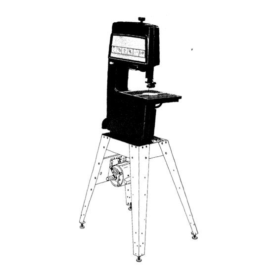
owners
manual
MODEL NO.
113.243401
SAW ON LY
MODEL NO.
113.243411
SAW WITH LEGS
AND MOTOR
Serial
Number
Mode{ and serial
number may be found
at the right-hand
side
of the frame.
You should record both
model and serial number
in a safe place for
future use.
CAUTION:
Read GENERAL and
ADDITIONAL
SAFETY
INSTRUCTIONS
carefully
12-INCH BAND SAW/
SANDER
• assembly
• operating
• repair
parts
Sold
by
SEARS,
ROEBUCK
AND
CO.,
Chicago,
IL.
60684
U.S.A.
PartNo. 69098
Printed In U.S.A.
Advertisement
Table of Contents

Related Manuals for Craftsman 113.243401


Summary of Contents for Craftsman 113.243401
- Page 1 1'Se'arsl owners manual MODEL NO. 113.243401 SAW ON LY MODEL NO. 113.243411 SAW WITH LEGS AND MOTOR Serial Number Mode{ and serial number may be found at the right-hand side of the frame. You should record both model and serial number in a safe place for future use.
-
Page 2: Safety Instructions
FULL ONE YEAR WARRANTY ON CRAFTSMAN BAND SAW If within one year from the date of purchase, this Craftsman Band Saw fails due to a defect in material workmanship, Sears will repair it, free of charge. WARRANTY SERVICE IS AVAILABLE... - Page 3 additional safety instructions for band saw/sander to keep blade breakage to a minimum, and to provide Safety is a combination operator common sense and maximum support for blade. alertness at all times when band is being used. When cutting a large piece of material, make sure it h°...
- Page 4 additional safety instructions for band saw/sander WARNING: THE 5" BAND SAW PULLEY AND THE WARNING: DO NOT ALLOW FAMILIARITY (GAINED 2-1/2" MOTOR PULLEY FURNISHED, WILL RUN THE FROM FREQUENT USE OF YOUR BAND SAW) TO BLADE APPROXIMATELY RPM (OR 2700 BECOME COMMONPLACE.
-
Page 5: Motor Specifications And Electrical Requirements
POWER This plug requires a mating 3-conductor grounded type CORD PLUG AND MOTOR RECEPTACLE. outlet as shown. THESE CRAFTSMAN MOTORS HAVE BEEN If the outlet you are planning to use for this power tool FOUND TO BE ACCEPTABLE FOR USE... -
Page 6: Table Of Loose Parts
unpacking and checking contents CONTENTS UNPACKING AND CHECKING CONTENTS ..Table Tilting ......ASSEMBLY Blade Guide Adjustment ....Installing Sawdust Elbow ....Lateral Guide Adjustment ....Blade Thrust Bearing Adjustment ..Assembling Steel Legs ....Guide Bar Lock Screw ....Installing Table ...... -
Page 7: Installing Sawdust Elbow
FOLLOWING PARTS INCLUDED WITH MODEL 113.243411 ONLY. I tern Description Qty. *Nut, Hex Head 1/2-13 ... * Nut Hex 1/4-20 ....*Screw Truss Hd. 1/4-20 x 5/8 ..* Lockwasher, 1/4 External ..* Foot, Leveling ....Motor ..........Channel, Support .... - Page 8 For the most efficient removal of sawdust, attach a Craftsman Home-n-Shop Vac to the sawdust elbow. TABLE TRUNNION INSTALLING TABLE Apply a coat of automobile wax to the table. 1. Place the table on the band saw so that the two trunnion...
- Page 9 MOUNTING BAND SAW/SANDER ON FLOOR STAND NOTE: For illustrative purposes, Band Saw is shown mounted on the Craftsman Catalog No. 9-22:236 Steel LEFT Set. This Leg Set is included with Model 113.243411. FOOT RIGHT 1. Remove Band cover applying...
- Page 10 assembly SETSCREW WRENCH 3/16x 3/16 KEY MOUNTING PULLEY 1. Loosen setscrew in the motor pulley and place the pulley on the shaft with the hub flush with the end of the shaft. Insert the motor shaft key and tighten the setscrew with 5/32"...
-
Page 11: Attaching B Elt Guards
RD SUPPORT ATTACHING B ELT GUARDS 1. Remove the pulley from the band saw, using the 5/32" setscrew wrench to loosen the screw. Be careful not to lose the shaft key. Attach the belt guard support with the three screws fur- nished with the guard. -
Page 12: Installing The Blade
assembly 5, Snap the guard into position as shown. 6. Look down into the guard . . . pull the belt upwards onto the motor pulley. 7. Insert the belt into the open end of the second belt guard, and out the round opening. Place the belt onto the band saw pulley by rotating the pulley. - Page 13 GUIDE BAR LOCK SCREW GUIDE 3. Loosen the guide bar lock screw and position the upper guide assembly approximately three inches above table as shown and tighten the lock screw. UPPER THRUST BEARING I I II1/8"SETSCREW 4. Loosen the two setscrews which lock...
- Page 14 assembly LOWER THRUST BEARING SETSCREW 6. Loosen the setscrew which locks the lower thrust bear- ing and turn the knob until the thrust bearing is all the LOWER way back. BLADE GUIDE SETSCREW 7. Carefully uncoil the blade, holding it at arms length. 8, Place the blade over the wheels with the teeth pointing downwards toward the table as shown.
- Page 15 THRUST BEARING The thrust bearings support the blade from the rear and will rotate when the blade is pushed against them while ADJ. KNOB THRUST BEARIN( cutting, soon as you stop cutting, bearings should stop rotating. 11. To be sure the thrust bearing is properly supporting the blade, turn the thrust bearing adjustment knob so that the bearing moves toward the blade and almost touches...
-
Page 16: On/Off Switch
assembly ADJUSTING THE TABLE 1. Find a 1/4-20 x 1 inch truss head screw, a regular washer, and a 1/4-20 wing nut among loose parts. Insert the screw into the hole in the table top as shown in the illustration at the bottom of page 15. - Page 17 3. To turn machine PUSH lever in. Never leave the machine unattended until it has come to a complete stop. 4. To lock switch in OFF position , . . hold switch IN with one hand . . . REMOVE key with other hand.
-
Page 18: Getting To Know Your Band Saw/Sander
getting to know your band saw/sander GUIDE BAR LOCK SCREW TENSION ADJUSTING KNOB--_ COVER RETAINING CLIP "_ TENSION SCALE ..ADJUSTMENT (Inside) DIAGRAMS (4-Used) ON-OFF SWITCH -_ BLADE GUARD )TOR CORD OUTLET <--UPPER BLADE GUIDE WORK LIGHT GUIDE "7 COVER •... -
Page 19: Guide Bar
9. GUIDE BAR When the upper guides are raised or lowered, they must not deflect the blade sideways. This means that the guide must be parallel to the blade, or square with =------_-_-_-_____= table. SCREW 1. Remove the blade guard, cover, blade, and the upper guide assembly. - Page 20 getting to know your band saw/sander 6. Attach the sanding platen to the guide bar with the same screw that held the upper blade guide assembly. Do not tighten the screw at this time. On the smooth side of the sanding belt, you will find a "directional arrow".
-
Page 21: Basic Band Saw/Sander Operation
Unlike a saw, it is not capable of doing inside cutting. Your Craftsman Band Saw/Sander is not only capable the usual band saw operations, but it can be converted into a sander as well. You can finish... -
Page 22: Maintenance
maintenance WARNING: FOR YOUR OWN SAFETY, TURN SWITCH "OFF" REMOVE PLUG FROM POWER SOURCE OUTLET BEFORE MAINTAINING OR LUBRICATING YOUR BAND SAW. MOTOR OUTLET ON-OFF SWITCH TIRES Pitch and sawdust that accumulate on the tires should be BLACK removed with a stiff brush or scraped off with a piece of wood. -
Page 23: Troubleshooting
trouble shooting WARNING: FOR YOUR OWN SAFETY, TURN SWITCH "OFF" AND REMOVE PLUG FROM POWER SOURCE OUTLET BEFORE TROUBLE SHOOTING YOUR BAND SAW/SANDER. TROUBLE PROBABLE CAUSE REMEDY Motor will not run. 1. Defective On-Off switch. Replace defective parts before using Defective switch cord. -
Page 24: Repair Parts Diagrams/Lists
CRAFTSMAN 12-INCH BAND SAW/SANDER, MODEL 113.243401 & 113.243411 "O "O SEE FIGURE EXPLODED VIEW 31 30 11 27 43 ..-.--._ m... - Page 25 CRAFTSMAN 12-INCH BAND SAW/SANDER, MODEL 113.243401 & 113.243411 Always order by Part Number - not by Key Number FIGURE 2 PARTS LIST PART PART DESCRIPTION DESCRI PTION 69069 453068 Cover, Frame with Trim *Screw, 5/16-18 x 3/4, Sems, Hex, Hd.
- Page 26 CRAFTSMAN 12-1NCH BAND SAW/SANDER, MODEL 113.243401 & 113.243411...
- Page 27 CRAFTSMAN 12-INCH BAND SAW/SANDER, MODEL 113.243401 & 113.243411 FIGURE 3 PARTS LIST PART PART DESCRI PTION DESCRI PTION STD522503 *Screw Hex Hd, Ty "T", 1/4-20 x 3/8 60190 Screw, Self-Locking, 5/16-18 x 3/8 STD551050 Washer, Plain, 1/2 x 1-1/4 x 1/8,...
- Page 28 ]Sears[ 12-INCH BAND SAW/ owners manual SANDER SERVICE that have purchased your 12-Inch Band Saw/Sander should need ever exist repair parts service, simply contact Sears Service Center most Sears, Roebuck stores. MODEL NO. sure provide pertinent facts when 113.243401 call or visit.
Need help?
Do you have a question about the 113.243401 and is the answer not in the manual?
Questions and answers