Table of Contents
Advertisement
Save
This
Manual
For Future
Reference
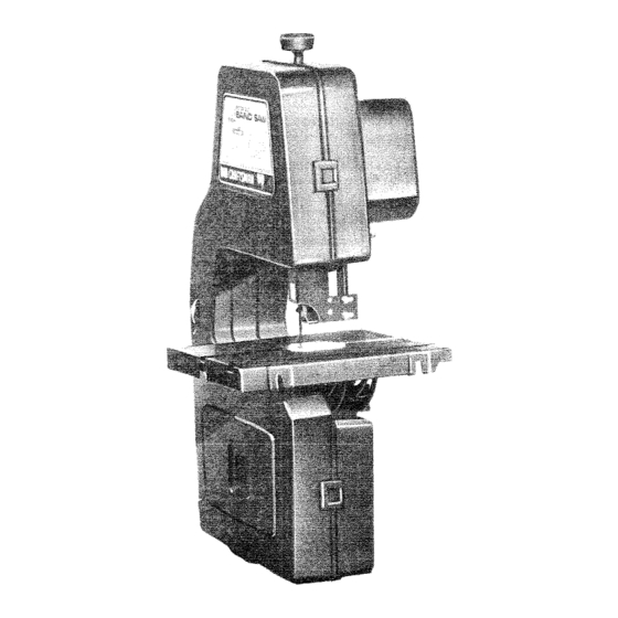
MODEL
NO.
11 3.244401
Serial
Number__
Model and serial
number may be found
at the right-hand
side
of the frame.
You should record both
model and serial number
in a safe place for
future use.
CAUTION:
Read GENERAL
and
ADDITIONAL
SAFETY
INSTRUCTIONS
carefully
IO-INCH
DIRECT
BAND
SA W
DRIVE
" assembly
e operating
= repair parts
Sold by SEARS,
ROEBUCK
AND
CO., Chicago,
IL. 60684
U.S.A.
Part No. 691 87
Printed in U.S,A.
Advertisement
Table of Contents

Related Manuals for Craftsman 113.244401


Summary of Contents for Craftsman 113.244401
- Page 1 Save This Manual For Future Reference MODEL 11 3.244401 Serial Number__ Model and serial number may be found at the right-hand side of the frame. You should record both model and serial number in a safe place for future use. IO-INCH DIRECT DRIVE...
- Page 2 ..FULL ONE YEAR WARRANTY ON CRAFTSMAN BAND if within one year from the date of purchase, this Craftsman Band Saw fails due to a defect in material or workmanship, Sears will repair it, free of charge. WARRANTY SERVICE iS AVAILABLE...
- Page 3 adamdonam safety instructions band Safety is a combination of operator common sense and When cutting a large piece of material, make sure alertness at all times when the band saw is being used. it is supported at table height, Hold the work firmly against the table, WARNING: FOR YOUR SAFETY,...
- Page 4 additional safety instructions for band saw YOUR The operation of any power tool can result in foreign objects being thrown into the eyes, which can result in severe eye damage. Always wear safety goggles com- plying with ANSI Z87.1 (shown on Package) before commencing power tool operation.
- Page 5 electrical motor specifications requirements GROUNDmNG This power tool is equipped with a 3-conductor cord and grounding type plug which has a grounding prong, approved by Underwriters' Laboratories and the Cana- dian Standards Association. The ground conductor a green jacket and is attached to the too! housing 3-PRONG !...o J-,-.44---I ¢...
- Page 6 unpacking and checking contents TOOLS NEEDED .._-- -_- Model 113.244401 Band Saw is shipped complete one carton but DOES NOT INCLUDE Steel Legs. COMBINATION SQUARE Separate all parts from packing materials and check each item with illustration and "Table of Loose Parts".
- Page 7 assernbly MOUNTING BAND SAW TO WORKBENCH If band saw is to be used in a permanent location, should be fastened securely to a firm supporting surface such as a workbench or accessory leg set, If mounting to a workbench, holes should be drilled through...
- Page 8 assembly INSTALLING THE TABLE Applying a coat of automobile wax to the table and inside surfaces of trunnion that slide on frame will ease sliding on these surfaces. --APPLY TO NSaDE Loosen the guide bar lock screw and position the upper guide assembly all of the way up.
- Page 9 assembly HEX HEAD SCREWS BLADE GUIDES--_ THRUST 3. Loosen the two cap screws that lock upper blade guides and separate them about 1/8 ': R© LLER ----_:_ 4. Find a Thrust Roller among loose parts and insert in upper guide assembly. 5.
- Page 10 assembly TENSION 15. Carefully uncoil the blade holding it at arms length. !6, Place the blade over the wheels with teeth pointing downward toward table as shown. Make sure the blade is in the center of the rubber INDICAT__ tires. WASHERJ NOTE: Your band saw can be used with 1/4 or 3/8 inch wide blades, 72 5/8 inches long.
- Page 11 assembly NOTE: IF BLADE CANNOT BE MADE TO RUN IN THE APPROXIMATE CENTER OF THE LOWER WHEEL, BE NECESSARY TO REPOSITION THE UPPER WHEEL ON THE MOTOR SHAFT. Loosen the set screw in the upper wheel. If the blade is running to the front of lower wheel - Slide upper wheel to the rear toward the motor.
- Page 12 assembly ADJUSTING GUIDE NOTE: When the upper guides are raised or lowered, they must not deflect the blade front to back or side- ways. This means that the guide bar must be parallel to the blade. 1. Lower guide until is approximately 1-3/4 inches above table.
- Page 13 assembmy !/y--- HEX HEAD ADJUSTBNG S_DE TO $_DE SQUARENESS SCREWS NOTE: When making adjustments, guide iock screw must be loosened. check squareness it must _GUiDEBAR be tightened. Loosen guide bar lock screw and lower g_Jide bar until it rests on table. Leave lock screw loose, _"...
- Page 14 assembly ADJUSTING UPPER THRUST ROLLER THRUST NOTE: thrust toilers support b}ade from ROLLER rear w_ll rotate when the blade is pushed against them wh_le are cutting. soon as you stop cut- ting, the rotters should stop rOtating, be sure thrust roller is properly supporting...
- Page 15 assembty ADJUSTING LOWER THRUST ROLLER THRUST ROLLER be sure thrust rotler is properly supporting ADJUSTMENT biade, turn thrust rol!er adiustment screw using 532" setscrew wrench that roller moves toward the blade and a!most touches, _CREW 2, Whiie turning upper wheel clockwise hand, adjust...
- Page 16 getting to know your band saw TENSSON SETTING (gNSODE} //---- TENSION ADJUSTMENT KNOB "-_ COVER RETAINING CLIP (5 USED) ON-OFF SWITCH GUIDE LOCK SCREW BLADE GUARD TABLE COVER BLADE GUIDES LOWER TILT BLADE SCALE GUIDES LOWER THRUST ROLLER ADJUSTMENT UPPER THRUST ROLLER ADJUSTMENT TABLE LOCK KNOB FRONT...
- Page 17 band getting to know" your To turn machir_e on, insert finger under switch 'ew!}_ arid pu4 e_d of switch out, To turnmachh_e OFF .. PUSH lever ir_. NEVER LEAVE MACHINE UNATTENDED UNTIL IT HAS COME TO A COMPLETE STOP. lock switch in OFF position.,,...
- Page 18 Do not altow pitch to accumulate on the table, blade sert. blade guides, or thrust rollers. Clean them with Craftsman and Pitch Remover. Apply a thin coat of automobile-type on the table so tt_e wood slides easily while cutting. Also...
- Page 19 troubleshooting WARNING: YOUR SAFETY, TURN SWITCH "OFF" REMOVE PLUG FROM POWER SOURCE OUTLET BEFORE TROUBLESHOOTING YOU_ BAND SAW. TROUBLE PROBABLE CAUSE REMEDY Motor will not run, Defective OnOff switch. Replace defective parts before using Defective switch cord. Band again, Defective switch box receptacle.
- Page 20 CRAFTSMAN 10-INCH BAND SAW, MODEL 113.244401 FIGURE...
- Page 21 CRAFTSMAN 10-INCH BAND SAW, MODEL 113.244401 Always order by Part Number not by Key Number FIGURE 1 PARTS LIST PART PART NAME NAME 69120 Trunnion 69031 Knob Asm, Tension 69121 Guide, Trunnion 60386 Washer, 15/32 x 1-3/8 x 3/64 60076 Washer, .505 x 7/8...
- Page 22 CRAFTSMAN 10-iNCH BAND SAW, MODEL 113.244401 oANY ATTEMPT TO REPAIR THIS MOTOR CREATE A HAZ- ARD UNLESS REPAIR IS DONE 43 i--,--_ QUALIFIED SERVICE TECHNICIAN. REPAIR SERVICE IS AVAILABLE AT YOUR NEAR- FIGURE EST SEARS STORE,...
- Page 23 CRAFTSMAN 10-iNCH BAND SAW, MODEL 113,244401 FIGURE 2 PARTS LIST PART KEY I PART NAME NAME NO. I 814584 Tire Screw, Spl. Hex Hd. 1/4-20 x 3-1/4 69117 69111 Bracket, Guide *Key, Square 3/16 x 15/16 STD5411!0 *Nut, Hex 10-32...
- Page 24 NO SAW 10-1NCH that you have purchased your l O-inch Band SERVICE should a need ever exist for repair parts service, sim- contact Sears Service Center most Sears, Roebuck and Co. stores. Be sure to provide all pertinent facts when you call or visit.
Need help?
Do you have a question about the 113.244401 and is the answer not in the manual?
Questions and answers
how long of blade foe craftman bandsaw model no 113.244401
The blade length for the Craftsman bandsaw model 113.244401 is not provided in the given context.
This answer is automatically generated