Table of Contents
Advertisement
Save This Manual
For Future Reference
owners
manual
MODEL NO.
113.247440
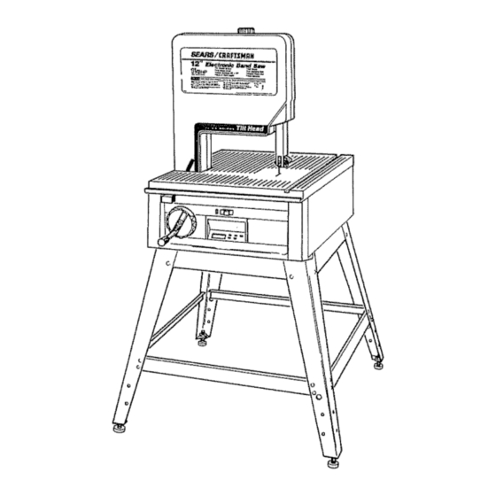
ELECTRONIC
BAND SAW
WITH LEG SET
S_dal
Number
Model and s_rial numbers
may b_ found
at the
left-hand
side of the bas_.
You should
record both
model
and s_rial number
in a safe place
for future
US¢
CAUTION:
READ ALL
INSTRUCTIONS
CAREFULLY
8EAIRS / CRRFTSMRN®
!2-|NCH ELECTRONIC
BAND SAW
® assembly
® operating
o repair parts
k_
Part No SP5225
j
k,..
j
Sold by SEARS, ROEBUCK AND CO., Chicago, IL.60684 U.S.A.
Printed in USA.
Advertisement
Table of Contents

Related Manuals for Craftsman 113.247440


Summary of Contents for Craftsman 113.247440
- Page 1 Save This Manual For Future Reference owners manual MODEL NO. 113.247440 ELECTRONIC BAND SAW WITH LEG SET S_dal Number Model and s_rial numbers 8EAIRS / CRRFTSMRN® may b_ found at the left-hand side of the bas_. You should record both model and s_rial number !2-|NCH ELECTRONIC...
- Page 2 FULL ONE YEAR WARRANTY ON CRAFTSMAN BAND SAW If within one year from the date of purchase, this Craftsman Band Saw fails due to a defect in material or workmanship, Sears will repair ft, free of charge. WARRANTY SERVtCE IS AVAILABLE...
- Page 3 additional safety instructions for band saw Safety is a combination of common sense, staying and lock knob, lower blade guide, tension adjust- alert, and knowing how your band saw works ing knob and tension scale, and blade thrust bearing adjustment BEFORE USING THE SAW:...
- Page 4 addffional safety instructions 2 Do not feed small pieces that require your I Never turn your band saw "ON" before clearing finger holding the workpiece to go under everything except the workpiece and related the guard area Use jigs or fixtures to hold feed or support devices off the table the work and keep your hands away from BEFORE...
-
Page 5: Table Of Contents
table of contents Page Page Location and Function of the Electronic General Safety tnstructions for Power Tools ..Additional Safety Instructions for Band Saw ..Indicator System ....... Before Using the Saw ......Digital Readout Display ....Function Keys ....... When Installing or Moving the Saw ..... - Page 6 electrical connections WARNING: TO MAINTAIN PROPER TOOL GROUND- ING WHENEVER THE OUTLET YOU ARE PLAN- POWER SUPPLY NING TO USE FOR THIS POWER TOOL IS OFTHE TWO PRONG TYPE, DO NOT REMOVE OR ALTER Motor Specifications THE GROUNDING PRONG IN ANY MANNER= The AC motor used in this saw is a capacitor-start, non-reversible type having the following...
- Page 7 5 Mostmotor troublesmaybetracedto looseor CAUTION: For circuits that are farther away from incorrectconnections, o verload, r educedinput electrical service box, the wire size must be increased vottage(suchas smallsize wire in the supply proportionately in order to deliver ample voltage to circuit) or to overly long supply circuit wire the saw motor.
- Page 8 unpacking and checking contents TABLE OF LOOSE PARTS Model 113o247440 Electronic Band Saw comes complete in one carton and includes steel legs ITEM DESCRIPTION QTY, AA Motor ........BB Basic Saw Assembly ....CC Owners Manual ......DD Leg ........EE Stiffener, Upper ......
- Page 9 °©c© LIST OF LOOSE PARTS IN BAG #507657 ITEM DESCRIPTION A Truss Head Screw 1/4-20 x 1/2 ... Lockwasher Ext, 1/4 ....C Hex Nut 1/4-20 ......D Leveling Foot ......E Hex ,Jam Nut 3/8-16 ...._t_'_t_,',\\\\\\\',\\\\\\\\\\\_ LIST OF LOOSE PARTS IN BAG #507655 ITEM DESCRIPTION OTY,...
- Page 10 assembly and amignment ASSEMBLING LEG SET From the loose parts bag find the following hard- ware: ITEM DESCRIPTION QTY_ A Truss Head Bolts 1/4-20 x 1/2 ... Lock Washers Ext 1/4 ....Hex Nuts 1/4-20 ......Leveling Feet ......E Hex Nut 3/8-16 ....... From the loose parts find the following items: ITEM...
- Page 11 MOUNTING MOTOR 1 Find the following parts: ITEM DESCRIPTION QTY_ AA Motor ........Spacer (1/40 D x 5/16) ....Flanged Locknut #10-32 ....M Wing Nut 5/16-18 ......Belt Tension Stud ......Motor Pulley w/Setscrew ....Poly"V" Belt ........Key3/16Sq x15/16 .....
- Page 12 SPACER 7 Carefully position the motor so that the poly "V" belt is around the motor pulley and the four motor studs align with the slots in the motor mount 8, Push motor studs through and install theflanged lock nuts to the three (3) motor studs with...
- Page 13 14 Belt tensioningis done by tighteningthe wing nut which pulls the motor down, The motor slideson the three (3}spacersand is locked place by the flanged lock nut at the threaded stud Belt tension is important Over tensioning cause vibration while too little tension may allow the belt to slip under heavy loads TIGHTEN FLANGE...
- Page 14 SELECTING BLADE SPEED The band saw has two speed settings: 3000 FPM for normal operation and 1500 FPM for operation requir- ing more control of the work piece. When changing speeds from 1500 to 3000 FPM remove the belt from the band saw pulley first. When going from 3000 to 1500 FPM remove the belt from the motor pulley first MOTOR...
- Page 15 ATTACHING TRIM CAPS & TRIM LEDGE 1 Locate the two (2) trim caps, the trim ledge, and from loose parts bag six (6) screws 1/4 x 1/2 2. Place the trim ledge against the bottom of the base, then reach through the base and secure the trim ledge with the two screws using a phillips PHI LLIPS SCREWDRIVER...
-
Page 16: Indicator System
getting to know your band saw LOCK KNOB BLADE GUIDES SLOT BEVEL LOCK KNOB ARING BLADE GUIDES HANDWHEEL ON-OFF SWITCH BLADE GUIDES ELECTRON_C/tNDICATOR SYSTEM BACK-UP BEARING GETTING TO KNOW YOUR BAND SAW I, Warning Labels 6 Lateral Blade Guide Adiustment - The guides can be adjusted sideways and locked in position 2 Tensions adiustment... -
Page 17: Digital Readout Display
Rocation and function of the electronic indicator system BATTERY COVER RELEASE SLOTS BATTERY COVER OPEN BATTERY OPEN BEVEL ANGLE KEY ELECTRONIC MEASUREMENT NSION SPEED KEY {FT. MIN_) DIGITAL READOUT DISPLAY DIGITAL READOUT DISPLAY FUNCTION KEYS The Liquid Crystal Display, or LCD, on this saw The five keys located to the right of the display are the function keys They are:... - Page 18 USING ELECTRONIC INDICATOR SYSTEM 1 Setting the Bevel Angle Reference Point 3 Blade Speed Whenever the battery is installed or a new zero digital display wilt read out one of two point is desired, it is necessary to set the zero starting speeds, depending on where the motor...
-
Page 19: Installing The Blade
INSTALLING BLADE LOCK KNOB Loosen the upper blade guide assembly lower to approximately 3 inches above rear table and retighten lock knob This is necessary make adjustments to blade guide and back up roller bearing 2 Remove the blade guard by loosening the two (2) _,DE GUARD MOUNTING... - Page 20 UPPER BACKUP 5 Loosen the setscrew which locks the upper back up bearing and push the bearing all the way back. Repeat procedure for tower back up bear- BEARING SETSCREW LOWER BACKUP BEARING SETSCI BLADE CENTERED CAUTION: To avoid being scraped, if the blade ON RUBBER TiRE should suddenly...
- Page 21 2oTurn the upperwheelby handa few timesand noticeifthebladeremains inthecenterofthetire on the top wheel, TRACKING ADJUSTMENT SCREW If the blademovesawayfromthe centerof the tire while you are turning it, the blade is not trackingproperly Thetop wheelshaftishingedsothebladecanbe tracked.Tilt the wheelby turning the tracking adjustment s crewusinga medium screwdriver (Seeillustration ) a.
- Page 22 6 To insure the backup bearing is properly sup- porting the blade, push the bearing toward the -T,i--f o-o,=o blade until it almost touches it Turn the upper wheel, by hand, checking the backup bearing to make sure it is not turning, If the bearing turning the blade is too close...
- Page 23 4, Locatethetwo(2)tablelatches, t wo(2)panhead screws,tockwashers, a nd hex nuts install the tablelatchesto the underside of thefrontof the basein holesprovided _HEXNUT ,,1- 1/4-20X L_,_ _LOW HEAD CAPSCREW 5 Locate the table alignment key and the two (2) 1/4-20 x 1 low head capscrews Install the key under the rear table miter gage slot and install the two screws but do not tighten at this time...
- Page 24 8 To keep the miter gage grooves in line, use a ftat blade screwdriver against the head of one of the low head capscrews in the miter gage groove to force the table alignment key firmly forward into the notch in the front table 9 While holding the alignment key into the notch,...
-
Page 25: On-Off Switch
location and function of controJs ON-OFF SWITCH NOTE: The On-Off switch has a locking feature This feature is intended to help prevent unauthorized possibly hazardous use by children and others 1 Insert ye!low key into switch 2 To turn on, insert finger under end of red switch lever and pull end out 3 To turn off switch, push red lever in towards the base... -
Page 26: Basic Band Saw Operation
It Mitering 1/4, 3/8, I/2 is not capable of doing inside cutting Beveling 1/4, 3/8, t/2 Your Craftsman Band Saw is not only capable of the Compound Cutting !/4, 3/8, 1/2 usual band saw operations, but it can be converted... - Page 27 INSTALLING SANDING ATTACHMENT UPPER BACKUP NOTE: The sanding beit cuts very rapidly Practice with some scraps of wood first before you attempt to BEARING SETSCREW sand your actual workpiece 1 To install the sanding belt and sanding platen, remove the front table, front cover, blade guard, and the blade 2 Use a 1/8-inch hex "L"...
-
Page 28: Recommended Accessories
recommended accessories Miter Gauge ........9-29929 Hold-Down Clamp for Miter Gauge ..9-29928 Stop-Rods for Miter Gauge ..... 9-29924 Rip Fence ........9-23402 Blades and Sanding Betts ..... See Catalog Circle Cutting Attachment ....9-23411 Power Tool Know How Handbooks Radial Saw (includes band saw section) ,, 9-29t7... -
Page 29: Maintenance
ADJUSTING BAND BEVEL TRAVEL or the back-up bearings Clean them with Craftsman Gum and Pitch Remover. if the band saw wiil not hold its position when at a bevel angle, and before the bevel lock is locked, or if CAUTION:... -
Page 30: Trouble Shooting
trouble shooting WARNING: FOR YOUR OWN SAFETY, TURN SWITCH "OFF" AND REMOVE PLUG FROM POWER SOURCE OUTLET BEFORE TROUBLE SHOOTING YOUR BAND SAW/SANDER. PROBABLE CAUSE REMEDY TROUBLE I Blade does not run in 1 Not tracking properly 1 Adjust tracking, see Assembly Section, /the approximate center "Installing... - Page 31 trouble shooting -- motor NOTE: Motors used on wood-working tools are particularly susceptible to the accumulation of sawdust and wood chips and should be blown out or "vacuumed" frequently to prevent interference with normal motor ventilation and proper operation of the centrifugally-operated starting switch REMEDY...
- Page 32 trouble shooting eBectronics PROBLEM PROBABLE CAUSE SUGGESTED CORRECTIVE ACTION qo display when 1 Battery incorrectly - Adjust battery position in compartment installed or missing - Install battery is pressed. 2 Battery contacts dirty - Clean battery contacts or corroded 3 Battery dead - Replace battery Battery is 6 volt, size J, alkaline type...
- Page 33 trouble shooting -- electronics PROBLEM PROBABLE CAUSE SUGGESTED CORRECTIVE ACTION - Select FPM function 1 Wrong display Display does not function selected change when blade speed is changed, - Have electronics checked by qualified 2 Encoder or digital technician, Repair service available at nearest display defective.
- Page 34 PARTS LIST FOR CRAFTSMAN 12-INCH ELECTRONIC BAND SAW MODEL 113.247440 "-o l ii...
- Page 35 PARTS LIST FOR CRAFTSMAN 12-INCH ELECTRONIC BAND SAW MODEL 113.247440 Always order by Part Number - Not by Key Number FIGURE 1 - DRIVE ASSEMBLY PARTS {ey" Part Part Description Description i ,i,i Screw, Hex Wash Hd 507830 Cover, Front w!Label...
- Page 36 PARTS LIST FOR CRAFTSMAN 12-INCH ELECTRONIC BAND SAW MODEL 113.247440 ]a.._. REAR VIEW OF ELECTRONIC CONTROL PANEL...
- Page 37 PARTS LIST FOR CRAFTSMAN 12-INCH ELECTRONIC BAND SAW MODEL 113.247440 Always order by Part Number - Not by Key Number FIGURE 2 - BASE COMPONENTS Part Ke'-yl Part Description Description ,No. 1 i lU ,u ,lllm_,l_, Cap, Trim L H 8t 6434 "['able, Front...
- Page 38 PARTS LIST FOR CRAFTSMAN 12-INCH ELECTRONIC BAND SAW iVi O D E L '1'13.247440...
- Page 39 PARTS LIST FOR CRAFTSMAN 12-INCH ELECTRONIC BAND SAW MODEL 1'13.247440 Always order by Part Number - Not by Key Number FIGURE 3 - BEVEL DRIVE MOTOR MOUNT ASSEMBLY PARTS Part Part Description Description STD541110 *Nut, Hex 10-32 816499 Handwheel Assembly...
- Page 40 PARTS LiST FOR CRAFTSMAN 12-INCH ELECTRONIC BAND SAW MODEL 11 &247440 FIGURE 4 - PARTS LIST Always order by Part Number - Not by Key Number Part Description .......... 815918 Stiffener, 817105 i815909 Stiffener, Lower STD541237 *Nut, Hex ,Jam 3/8-16...
- Page 41 NOTES...
- Page 42 NOTES...
- Page 43 NOTES...
- Page 44 ,, ii lu, i i, i ,ill, 12-iNCH ELECTRONIC BAND SAW owners manual SERVICE Now that you have purchased your 12-1nch Electronic Band Saw, should a need ever exist for repair parts or service, simply contact any Scars SCMce Center and most Scars, Roebuck and Co.
Need help?
Do you have a question about the 113.247440 and is the answer not in the manual?
Questions and answers