Table of Contents
Advertisement
owners
manual
MODEL NO.
113.242700
SAW ONLY
113.242720
SAW WITH LEGS AND
TWO TABLE EXTENSIONS
Serial
Number
Model and serial
number may be found
at the right-hand side
of the base.
You should record both
model and serial number
in a safe place for
future use.
CAUTION:
Read
GENERAL
and
ADDITIONAL
SAFETY
INSTRUCTIONS
carefully
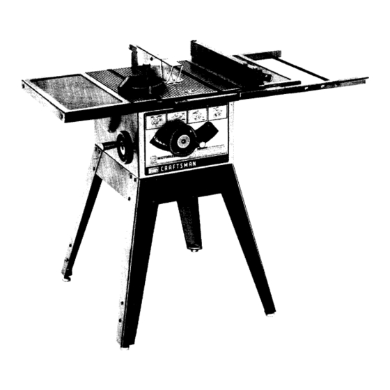
CRAFTSMAN°
9 INCH
MOTORIZED
TABLE SAW
• assembly
• operating
• repair
parts
Sold by SEARS,
ROEBUCK
AND
CO., Chicago,
IL. 60684
U.S.A.
Part No. 62789
Printed in U.S.A.
Advertisement
Table of Contents

Related Manuals for Craftsman 113.242720


Summary of Contents for Craftsman 113.242720
- Page 1 SAW WITH LEGS AND TWO TABLE EXTENSIONS Serial Number Model and serial number may be found at the right-hand side of the base. CRAFTSMAN° You should record both model and serial number in a safe place for future use. 9 INCH MOTORIZED CAUTION:...
- Page 2 FULL ONE YEAR WARRANTY ON CRAFTSMAN TABLE SAWS If within one year from the date of purchase, this Craftsman Table Saw fails due to a defect in material or workmanship, Sears will repair it, free of charge. WARRANTY SERVICE IS AVAILABLE...
- Page 3 ADDITIONAL SAFETY INSTRUCTIONS FOR TABLE SAWS WARNING: YOUR SAFETY, thrown back at the operator at excessive speed. OPERATE YOUR SAW UNTIL IT IS COMPLETELY This can usually be avoided by keeping the guard ASSEMBLED AND INSTALLED ACCORDING TO THE and spreader in place for all "THRU-SAWlNG"...
-
Page 4: Motor Specifications
DO NOT remove small pieces of cut-off material 16. Never feed material into the cutting tool from the rear of the saw. An accident and serious injury could that may become trapped inside the blade guard result. while the saw is running. This could endanger your hands or cause a kickback. - Page 5 If your is for use on less than 150 volts it has a plug If the outlet are planning to use for this saw is of the that looks like below. prong type REMOVE ALTER GROUNDING PRONG IN ANY MANNER. Use an adapter 3-PRONG PLUG...
-
Page 6: Unpacking And Checking
UNPACKING AND CHECKING CONTENTS TOOLS NEEDED WARNING: YOUR SAFETY, NEVER CONNECT PLUG TO POWER SOURCE OUTLET UNTIL Medium Screwdriver ASSEMBLY STEPS ARE COMPLETE, HAVE READ AND UNDERSTAND THE SAFETY AND OPERATIONAL INSTRUCTIONS. Hammer LIST OF LOOSE PARTS #2 Phillips Screwdriver Part Name Qty. -
Page 7: Checking Table Insert
Lockwasher, 1 /4 in. ExternalType (approx.dia. of hole 1/4 in.) ....Lockwasher,5/16 in. ExternalType (approx.dia. of hole 5/16 in.) ....Hex Hd. Screw, 5/16-18 x 1-1/2 in. long ..Hex Hd. Screw, 5/16-18 x 1 in. long ... ¢ TrussHeadScrew, 1/4-20 x 5/8 ....The following parts are included with Model 113.242720... - Page 8 If the insert is BELOW the table surface, remove insert and bend the tabs (with pliers) enough to make the insert ABOVE the table surface. To replace insert. Place insert into insert opening table push toward rear engage spring clip until keyslot in insert will drop...
- Page 9 EXT. LOCKWASHER HEX. HEAD SCREW 5/16 I IN. LONG FLAT WASHER INSTALLING RIP FENCE GUIDE BARS From among loose parts find following hardware: 5/16 REAR GUIDE 2 Hex. Head Screws, 5/16- 18 x 1-1/2 in. long 2 Hex. Head Screws, 5/16- 18 x 1 in. long 4 Hex.
-
Page 10: Assembling Steel Legs
SCREWS THROUGH HOLES MARKED "X" ASSEMBLING STEEL LEGS NOTE: Steel Legs are furnished with Model 113.242720. From among the loose parts, find the following Hardware: 24 Truss Head Screws, 1/4 - 20 x 5/8 in. long (top of STIFFENER screw is rounded) 24 Lockwashers, 1/4 in. -
Page 11: Aligning T Able Extensions
ALIGNING T ABLE EXTENSIONS "Tap" extensions upwards or downwards, using a block of wood and a hammer until they are even with top of saw table. Be sure end of extensions are even with front BLOCK OF WOOC edge of saw. 2. - Page 12 rip fence must be PARALLEL with the sawblade and Miter Gauge grooves... Move fence until it is along side of groove. Do NOT LOCK IT. It should be parallel to groove. If it is not; Loosen the two "Hex. Head Screws." Hold fence head tightly...
- Page 13 I NDI CATOR ADJUSTING RIP SCALE INDICATOR 1. Turn ELEVATION handwheel clockwise until blade is up as high as it will go. IMPORTANT: BLADE must SQUARE (90 ° ) to TABLE, in order to ALIGN rip fence. Position fence right side sawblade so that...
- Page 14 Lay a piece of flat straight wood and a square on saw table and rotate the SPREADER SUPPORT until the bracket is aligned with square. 7. MAKE SURE END OF SUPPORT, BRACKET ROD ARE EVEN . .. using an 1/8 in. setscrew wrench, TIGHTEN THE SET SCREWS ONLY.
-
Page 15: Getting To Know Your
GETTING TO KNOW YOUR BLAOE GUARD ANTIKICKBACK MITER GAUGE PAWLS LOCK KNOB BLADE MITER GAUGE SPREADER RIP FENCE HEAD 5 MITER GAUGE HOLES TABLE INSERT FACING TILT HANDWHEEL ELEVATION RIP FENCE LOCK KNOB ON-OFF SWITCH ON-OFF SWITCH CAUTION: Before turning switch on, make sure the blade guard is correctly installed and operating... - Page 16 ELEVATION HANDWHEEL . . . elevates or lowers the blade. Turn clockwise to elevate ... counterclockwise to lower. NOTE: WHEN THE BLADE IS TILTED TO 45 ° , IT CANNOT BE LOWERED THE WAY BELOW THE TABLE. IT WILL PROJECT APPROX. 1/2 IN.
-
Page 17: Basic Saw Operation
PULL TO LOOSEN 8 REMOVING AND INSTALLING SAWBLADE PUSH TO TIGHTEN '_ /' WARNING: FOR YOUR OWN SAFETY, TURN SWITCH "OFF" REMOVE PLUG FROM POWER SOURCE OUTLET BEFORE REMOVING INSTALLING SAWBLADE. A. Remove insert. B. Place ARBOR wrench on flat surfaces of saw ARBOR WRENCH ARBOR... - Page 18 THESE EDGES MUST PLYWOOD BE PARALLEL F,-4-3,/4 -,.J PLYWOOD NOTE: dimensions in inches PUSH STICK PUSH BLOCK PUSH STICK PUSH BLOCK Make the Push Stick using a piece of 1 x 2, or rip one from 3/4 PLYWOOD a wide board, say 11-1/2 in.
-
Page 19: Repetitive Cutting
When cutting long workpieces, invert the AUXILIARY FENCE/WORK SUPPORT, and position it on top of the guide bars to support the workpiece as near to the end as possible. If this does not adequatply support the workpiece, you can make a simple support by clamping a piece of plywood to a sawhorse. -
Page 20: Miter Cutting
MITERCUTTING MITER CUTTING is known as cutting wood at an angle other than 90 ° with the edge of the wood. Follow the same procedure as you would for crosscutting. Adjust the miter gauge to the desired angle, and lock it. The miter gauge may be used in either of the grooves in the table. - Page 21 RIPPING ALWAYS SUPPORT LONG WORKPIECES RIPPING is know as cutting a piece of wood with the grain, or lengthwise. This is done using the rip fence. Position the fence to the desired WIDTH OF RIP and lock in place. Before starting to rip, be sure Rip Fence is parallel to sawblade.
-
Page 22: Operation
Feed workpiece hand along AUXLIARY FENCE!WORK SUPPORT until the end is approx. 1 in. past the front edge of the table. Continue to feed using the PUSH BLOCK. Hold workpiece position install PUSH BLOCK sliding AUXILIARY FENCE/WORK SUPPORT (this may raise guard). BAFFLE Narrow strips thicker than the Auxiliary FenceANork Support... -
Page 23: Molding Cutting
RABBETING Rabbeting is known as cutting a section of the corner FIRST of a piece of material, across an end or along an edge. RABBET To make a RABBET requires cuts which do not go all the through the material. Therefore the blade guard... -
Page 24: Miter Gauge
ADJUSTMENTS LOCK KNOB WARNING: FOR YOUR OWN SAFETY, TURN SWITCH "OFF" REMOVE PLUG FROM POWER SOURCE SQUARE OUTLET BEFORE MAKING ANY ADJUSTMENTS. MITER GAUGE NOTE: graduations miter gauge provide accuracy average woodworking. In some cases where extreme accuracy is required, when making angle cuts, for example,... - Page 25 BLADE TILT, OR SQUARENESS OF BLADE TO TABLE 90 ° (SQUARE) and 45 ° (BEVEL) STOP COLLARS. When the bevel pointer is pointing directly to the "'0" mark on the bevel scale, the sawblade should make a SQUARE cut 90 ° to the table. To check for SQUARENESS: WARNING: FOR YOUR...
- Page 26 If blade is NOT 45 ° to table the 45 ° STOP COLLAR 45° STOP COLLAR and SCALE must be ADJUSTED Remove Elevation Handwheel. TILT SCREW Using a small size screwdriver, reach thru curved slot in front trim panel and loosen BOTH setscrews in 45 °...
-
Page 27: Maintenance
Frequently clean your cutting tools with Craftsman and Pitch Remover. A coat of automobile-type applied to the table will help to keep the surface clean and allow workpieces to slide more freely. - Page 28 TROUBLE SHOOTING WARNING: FOR YOUR OWN SAFETY, TURN SWITCH "OFF" AND ALWAYS REMOVE PLUG FROM POWER SOURCE OUTLET BEFORE TROUBLESHOOTING. TROUBLE SHOOTING -- GENERAL PROBABLE CAUSE REMEDY TROUBLE 1. Discard Blade and use a different blade. Blade out of balance. Excessive vibration.
- Page 29 TROUBLE SHOOTING -- MOTOR (Continued) TROUBLE PROBABLE CAUSE REMEDY Motor starts slowly 1. Low voltage will not 1. Request voltage check from the power company. or fails to come up trip relay. to full speed. 2. Windings burned 2. Have motor repaired or replaced.
- Page 30 PARTS LIST FOR CRAFTSMAN 9 INCH MOTORIZED MODEL NO. 113.242700 & 113.242720 22 21 Figure...
- Page 31 PARTS LIST FOR CRAFTSMAN 9 INCH MOTORIZED MODEL NO. 113.242700 & 113.242720 Always order by Part Number - not by Key Number. FIGURE 1 PARTS LIST Part Part Description Description 62770 62782 Rod, Separation (Includes Key No. 18) Fence Assembly,...
- Page 32 PARTS LIST FOR CRAFTSMAN 9 INCH MOTORIZED MODEL NO. 113.242700 & 113.242720 17 16 * If this part is removed, discard replace with a new push nut. ¢ 40_\\ 37 36 Figure 2...
- Page 33 PARTS LIST FOR CRAFTSMAN 9 INCH MOTORIZED MODEL NO. 113.242700 & 113.242720 FIGURE 2 PARTS LIST Part Part Description Description 62628 Table, Saw 62633 Base, Saw 805297-1 Screw, Flat 5/16-18 x 1-1/4 STD 600603 *Screw, Type "T" Pan No. 6-32 x 3/8 STD 511107 *Screw, Pan Hd.
- Page 34 PARTS LIST FOR CRAFTSMAN 9 INCH MOTORIZED MODEL NO. 113.242700 & 113.242720 FIGURE 3 - 62782 FENCE ASSEMBLY Part Description 62782 Fence Assembly, 62693 Plug, Button 62692 Knob (Includes Key No. 1) STD 551031 *Washer, 21/64 x 1/2 x 1/32 62775 Indicator.
-
Page 35: Gauge Assembly
PARTS LIST FOR CRAFTSMAN 9 INCH MOTORIZED MODEL NO. 113.242700 & 113.242720 \ 11 FIGURE 4 -- 62694 MITER GAUGE ASSEMBLY Part Description 62694 Miter Gauge Assembly 62693 Plug, Button 62692 Knob (Includes Key No. 1) STD 551031 *Washer, 21/64 x 1 x 1/16... - Page 36 PARTS LIST FOR CRAFTSMAN 9 INCH MOTORIZED MODEL NO. 113.242700 & 113.242720 " * If this part is removed, discard and replace with a new push nut. FIGURE 5 - 62637 BLADE GUARD ASSEMBLY Part Description 62637 Guard Assembly 62415...
- Page 37 PARTS LIST FOR CRAFTSMAN 9 INCH MOTORIZED MODEL NO. 113.242700 & 113.242720 FIGURE MODEL 113.242720 ONLY Part Description 60314 Screw, Serrated Truss Hd. 1/4-20 x 5/8 62552 62554 Stiffener, Side STD 551225 * Lockwasher, Ext. 1/4 STD 541025 *Nut, Hex 1/4-20...
- Page 38 PARTS LIST FOR CRAFTSMAN 9 INCH MOTORIZED MODEL NO. 113.242700 & 113.242720 TABLE _,EF) FIGURE 7 -- TABLE EXTENSION FOR MODEL 113.242720 ONLY Part Description 62546 tExtension Assembly, Complete 60323 Screw, Serrated Truss Hd. 1/4-20 x 1" 62547 Extension 62549 Bracket, Corner Support No.
- Page 39 NOTES...
- Page 40 [Sears ! owners 9 INCH MOTORIZED TABLE SAW manual SERVICE Now that you have purchased your 9 inch motorized table saw should a need ever exist repair parts or service, simply contact any Sears Service Center and most Sears, Roebuck and Co.
Need help?
Do you have a question about the 113.242720 and is the answer not in the manual?
Questions and answers