Table of Contents
Advertisement
Sears
owners
manual
MODEL NO.
113.24140
CAUTION:
Read
GENERAL
and
ADDITIONAL
SAFETY
INSTRUCTIONS
carefully
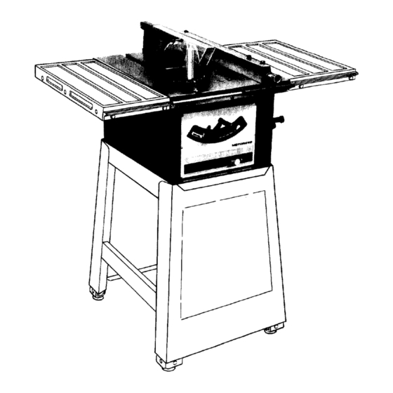
CRRFTSMRN
9-INCH
MO TORIZED
TABLE
SAW
assembly
operating
repair
parts
SEARS, ROEBUCK AND
CO., Chicago,
IL 60684
U.S.A. and SIMPSONS-SEARS
LIMITED, Toronto
Part No. 62446
Printed in U.S.A.
I
II
I
II I
I
I
II
III
I
I I i
III
Advertisement
Table of Contents

Related Manuals for Craftsman 113.24140


Summary of Contents for Craftsman 113.24140
- Page 1 Sears owners manual MODEL NO. 113.24140 CRRFTSMRN 9-INCH MO TORIZED CAUTION: TABLE Read GENERAL ADDITIONAL SAFETY assembly INSTRUCTIONS operating carefully repair parts SEARS, ROEBUCK AND CO., Chicago, IL 60684 U.S.A. and SIMPSONS-SEARS LIMITED, Toronto Part No. 62446 Printed in U.S.A. II I I I i...
-
Page 2: Safety Instructions
general safety instructions for power tools USE SAFETY GOGGLES 1. KNOW YOUR POWER TOOL Read owner's manual carefully. Learn Safety gogglesmust comply with ANS Z87.1-1968. application and limitations as well as the specific Also use face or dust mask if cutting operation dusty. -
Page 3: For Table Saws
additional safety instructions for table saws WARNING: YOUR SAFETY, extra caution when guard assembly ATTEMPT TO OPERATE YOUR SAW UNTIL IT IS removed resawing, dadoing, rabbeting, COMPLETELY ASSEMBLED INSTALLED molding replace guard as soon as that ACCORDING TO THE INSTRUCTIONS . - Page 4 Lubrication ......... Recommended Accessories ..... Trouble Shooting ......Repair Parts ......... Your Craftsman 9 inch Motorized Table Saw is shipped complete in one carton. Floor base and table extensions are Key No. Part Name Qty. optional accessories. Miter Gauge......Separate all parts from packing materials and check each BladeGuardandSpreader ....
- Page 5 MOUNTING SAW ON CRAFTSMAN FLOOR BASE Place saw on base so that front corners of saw are even with corners of base. Find four hex. head bolts 3/4 in. long, nuts and washers furnished with base. Insert all four bolts through holes in saw and base ...
-
Page 6: Installing Blade Guard
assembly WiNG SCREW CARRIAGE BOLT CLAMP BLOCK INSTALLING BLADE GUARD Find the parts shown among the loose parts ... attach to spreader support rod at the back of the saw ... screw in wing screws ... screw on nuts but DO NOT TIGHTEN THEM. -
Page 7: Loose Parts List
IMPORTANT: Make a black pencil line on the guide bar at rip fence head. This will explained further this manual under "Basic Operation" . .. ripping Place BLADE GUARD on table .., engage slots in SPREADER with WING SCREWS move spreader toward front of saw so that wing screw is at end of slot •.. -
Page 8: Getting To Know Your Saw
getting to know your saw ANTI-KICKBACK PAWLS MITER GAUGE LOCK HANDLE HOLES ATTACHING FACING RIP FENCE LOCK ELEVATION CRANK TILT CRANK RESET BUTTON ON-OFF SWITCH ELEVATION CRANK ... elevatesor lowersthe blade. RESET BUTTON ..See "Motor Specifications and Turn counterclockwise to elevate clockwise to Electrical... -
Page 9: Removing And Installing
PULL LOOSEN REMOVING AND INSTALLING SAWBLADE WARNING: FOR YOUR OWN SAFETY, TURN SWITCH "OFF" REMOVE PLUG FROM POWER SOURCE OUTLET BEFORE REMOVING INSTALLING SAWBLADE. Remove insert. OPEN WRENCH Place OPEN wrench flat surfaces ARBOR wrench position wrenches as shown hold your hands well... -
Page 10: Motor Specifications
motor specifications and electrical requirements MOTOR SPECl FICATIONS IF YOU NOT SURE THAT YOUR OUTLET PROPERLY GROUNDED, HAVE IT CHECKED BY A motor used this is a capacitor start, QUALIFIED ELECTRICIAN. non-reversible type, with the following specifications: Voltage ........ WARNING: DO NOT PERMIT FINGERS... -
Page 11: Basic Saw Operation
basic saw operation recommend following instructions operating 6. Do not stand directly in front of the blade in case of a your saw so that you get the best results and to minimize KICKBACK. Stand to either side of the blade. the likelihood of personal injury. - Page 12 Elevation screw threads and pivot nut. (First Clean with with proper lubricant and require no additional lubrication. Craftsman gum & pitch remover. The following parts should be oiled occasionallv with Cradle bearing points. No. 20 or No. 30 engine oil.
-
Page 13: Ripping
RIPPING, BEVEL RIPPING, RESAWINGAND Have blade extend approximately 1/8 inch above top of RABBETING (alongthe edgeof a workpiece) a re workpiece. Additional blade exposure could performedusing the RIP FENCE togetherwith hazardous. AUXILIARY devices when required. Do not stand directly in front of the blade in case of a WARNING: FOR YOUROWNSAFETY, A LWAYS KICKBACK. - Page 14 basic saw operation ALwAvs,op , LONO WORKP[ECES WORK SUPPORT Use a "saw horse" and a piece of plywood. When "WIDTH OF RIP" is 6 inches and WIDER use your RIGHT hand to feed the workpiece until it is clear of the table.
- Page 15 NARROW RIPPING - SHORT PIECES - UP TO 18" Position the AUXILIARY FENCE to the desired WIDTH OF RIP lock RIP FENCE in place. Hold workpiece against AUXILIARY FENCE feed with RIGHT hand guide with LEFT hand until clear of table.
-
Page 16: Resawing
basic saw operation Hold workpiece against AUXILIARY FENCE feed with RIGHT Hand guide with LEFT hand until clear of table, BAFFLE When ripping thin strips that may enter the guard and strike the baffle, CAREFULLY raise guard only enough to clear the workpiece. -
Page 17: Operation
RABBETING Rabbeting is known as cutting out a section of the corner of a piece of material. To make a RABBET requires two cuts which do not go all RABBET the way through the material. Therefore blade guard must be removed. Remove blade guard. -
Page 18: Rip Fence
adjustments 3/16 iNCH SCREW WRENCH SCREWS tooth does touch same amount mechanism underneath must be adjusted to make the blade PARALLEL to GROOVE. Loosen four (4) screws (about 1/2 turn) using 3/16 inch setscrewwrench furnished with saw, Move of the SPREADER SUPPORT right... - Page 19 BLADE TILT, OR SQUARENESS OF BLADE TO TABLE 90 ° (SQUARE) and 45 ° (BEVEL) STOP COLLARS. When the bevel pointer is pointing directly to the "0" mark on the bevel scale, the sawblade should make a SQUARE cut 90 ° to the table. To check for SQUARENESS: WARNING;...
-
Page 20: Maintenance
Frequently clean your cutting tools with Craftsman Gum and Pitch remover. A coat of automobile-type wax applied to the table will help to keep the surface clean and allow workpieces to slide more freely. - Page 21 2. Elevation screw threads and pivot nut. (First Clean with with proper lubricant and require no additional lubrication. Craftsman gum & pitch remover. The following parts should be oiled occasionally with SAE 3. Cradle bearing points.
-
Page 22: Troubleshooting
trouble shooting WARNING: FOR YOUR OWN SAFETY, TURN SWITCH "OFF" ALWAYS REMOVE PLUG FROM POWER SOURCE OUTLET BEFORE TROUBLE SHOOTING. TROUBLESHOOTING- GENERAL PROBABLE CAUSE REMEDY TROUBLE Blade out of balance. 1. Discard Blade and use a different blade. Excessive vibration. Miter gage not adjusted 1. - Page 23 TROUBLE SHOOTING - MOTOR(continued) TROUBLE PROBABLE CAUSE REMEDY 1. Power line overloaded with Motor fails to develop 1. Do not use other appliances or motors full power. (Power lights, appliances when using the saw. output of motor decreases other motors. rapidly with decrease in 2.
- Page 24 Figure...
- Page 25 All parts illustrated in Figures 1 through 5 and listed under part numbers may be ordered through any Sears retail mail order store. Order parts by mail from the catalog order store which serves the territory in which you live. In several instances, part numbers are listed...
- Page 26 "0 "0 •_ 3> ATTEMPT TO REPAIR THIS MOTOR CREATE A HAZARD UNLESS REPAIR IS DONE BY QUALIFIED SERVICE TECHNICIAN, REPAIR SERVICE IS AVAILABLE AT YOUR NEAREST SEARS STORE. 31 32 3 o'n -I CJcn 16 24 r"3> ._.0 o.-i 14 15 14 18 17 14 15 14 Figure 2...
- Page 27 FIGURE "o Part Part Description Description 805297-1 62438 *Screw, Socket Flat Hd.5/16-18x1-1/4 Screw, Tilt 62425 62432 Table, Support, Bearing 60302 60031 Ring, Retaining 7/16 Washer, .440 x 11/16 x 1/32 "11 62430 • Motor and Control 62433 Clamp 62434 138167 Nut, Pivot * Lockwasher,I nternal...
-
Page 28: Repair Parts
PARTS LIST FOR CRAFTSMAN g-INCH MOTORIZED TABLE SAW MODEL NO. 113.24140 11 12 FIGURE 62418 RIP FENCE ASSEMBLY Part Description 62418 Fence Assembly 62132 Knob, Fence Adjusting 60067 *Screw, Hex Soc.Cup Pt. Set, I/4-20 x 1/4 62424 Insert... -
Page 29: Gauge Assembly
PARTS LIST FOR CRAFTSMAN 9-INCH MOTORIZED ;TABLE SAW MODEL NO. 113.24140 FIGURE 62070 MITER GAUGE ASSEMBLY Part Description 62070 tGauge Assembly, Miter 62068 Handle, Miter Gauge 60024 *Washer, Plain, .320 x 1 x 1/16" 3:62014 Gauge, Miter 9404365 *Screw, Mach., No. - Page 30 PARTS LIST FOR CRAFTSMAN 9-INCH MOTORIZED TABLE SAW MODEL NO. 113.24140 FIGURE 5 - 62417 BLADE GUARD ASSEMBLY Part Description 62417 Guard Assembly 62415 Guard 60004 Ring, Retaining 60128 *Washer,17/64 x 5/8 x 1/32 62416 Pin, Guard 62413...
- Page 32 Sears CRRFTSMRN 9-INCH MO TORIZED owners manual TABLE The Model Number will be found on a plate attached to your MODEL NO. saw, at the left-hand side of the base. Always mention Model Number when requesting service or repair parts for your Table Saw.
Need help?
Do you have a question about the 113.24140 and is the answer not in the manual?
Questions and answers