Table of Contents
Advertisement
ISears]
owners
manual
MODEL NO.
113.29570
SAW ONLY
113.295750
SAW WITH LEGS AND
TWO TABLE EXTENSIONS
Serial
Number
.......
Model and serial
number may be found
at the right-hand
side
of the base.
You should record both
model and serial number
in a safe place for
future use,
CAUTION:
Read
GENERAL
and
ADDITIONAL
SAF ETY
INSTRUCTIONS
carefully
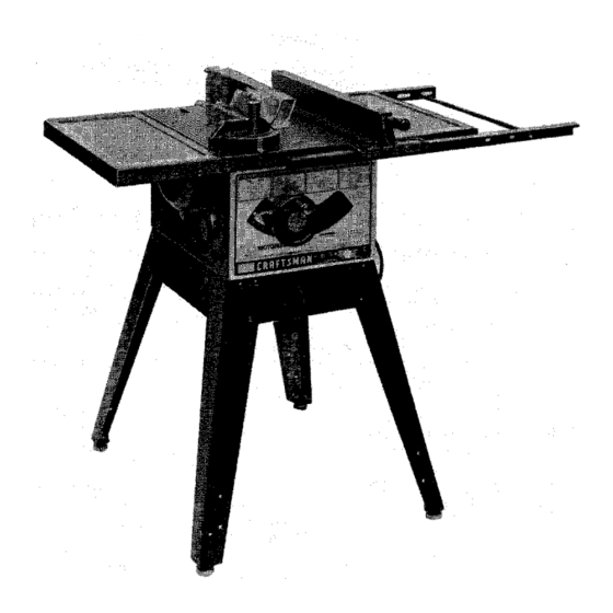
CRAFTSMAN°
IO-INCH
MOTORIZED
TABLE SAW
• assembly
• operating
• repair parts
Sold by SEARS,
ROEBUCK
AND
CO.,
Chicago,
IL
60684
U.S.A.
Part No. 62716
Printed in U_S.A.
Advertisement
Table of Contents

Related Manuals for Craftsman 113.29570


Summary of Contents for Craftsman 113.29570
- Page 1 Serial Number ..Model and serial number may be found at the right-hand side of the base. You should record both CRAFTSMAN° model and serial number in a safe place for future use, IO-INCH MOTORIZED CAUTION: TABLE SAW Read GENERAL ADDITIONAL •...
-
Page 2: Warranty
FULL ONE YEAR WARRANTY ON CRAFTSMAN TABLE SAWS If within one year from the date of purchase, this Craftsman Table Saw fails due to a defect in material workmanship, Sears will repair it. free of charge. WARRANTY SERVICE IS AVAILABLE... -
Page 3: General Safety Instructions
ADDITIONAL SAFETY INSTRUCTIONS FOR TABLE SAWS WARNING: YOUR SAFETY, contact rear revolving blade OPERATE YOUR SAW UNTIL IS COMPLETELY thrown back at the operator at excessive speed. This ASSEMBLED AND INSTALLED ACCORDING TO THE can usually be avoided by keeping the guard and INSTRUCTIONS ... -
Page 4: Motor Specifications
B. Never use grinding wheels, abrasive cut-off wheels, 16. Never feed material into the cutting tool from the rear friction wheels (metal slitting blades) wire wheels or of the saw. An accident and serious injury could result. buffing wheels, 17. THINK SAFETY. -
Page 5: Table Of Contents
"If yoursaw is for use on lessthan 150 volts it has a plug If the outlet you are planning to use for this saw is of the that looks like below. two prong type DO NOT REMOVE OR ALTER 3-PRONG PLUG GROUNDING PRONG IN ANY MANNER. -
Page 6: Tools Needed
UNPACKING AND CHECKING CONTENTS WARNING: YOUR SAFETY, NEVER z//_ TOOLS NEEDED CONNECT PLUG TO POWER SOURCE OUTLET UNTIL ASSEMBLY STEPS ARE COMPLETE, AND YOU HAVE READ AND UNDERSTAND THE SAFETY OPERATIONAL INSTRUCTIONS. Hammer Medium Screwdriver Small Sorewdriver LIST OF LOOSE PARTS PartName Qty, Miter Gauge ......1... -
Page 7: Assembly
Lockwasher, 5 /16 in. ExternalType (approx.dia. of hole5/16 in.) ....Luckwashar-#10 ExternalType (approx.die. of hole3/18 in.) ....WingScrew, 1/4-20 x 1/2 {n.long ..... Rex Hd. Screw, 5/16 - 18 x 1-1/2 im long ..Hex Hd, Screw,5/16 - f8 x 1 in. tong ..Screw,Pro1 Hd. -
Page 8: Checking Blade Squareness To Table
If the insert is BELOW the table surface, remove the insert and bend the tabs (with pliers) enough to make the insert ABOVE the table surface. To replace insert. Place insert into insert opening in table and push toward rear of saw to engage spring clip and until keyslot in insert wi!l drop over screw. -
Page 9: Installing Rip Fence Guide Bars
EXT. LOCKWASHER HEX. HEAD SCREW 5/16 I IN. LONG FLAT WAS½ER INSTALLING RIP FENCE GUIDE BARS 1. From among the loose _rts find the following hardware: HEX NU 5/16 2 Flex. Head Screws. 5/16 - 18 x 1-I/2 in. long 2 Flex. -
Page 10: Assembling Steel Legs
SCREWS THROUGH HOLES MARKED "X" ASSEMBLING STEEL LEGS NOTE: Steel Legs are furnished with Model 113.295750, From among the loose parts, find the following Hardware: 24 Truss Head Screws, 1/4 - 20 x 5/8 in. long (top of SIDE STIFFENER screw is rounded) 24 Lockwashers, 1/4 in. -
Page 11: Aligning Table Extensions
ALIGNING TABLE EXTENSIONS 1. "TAD" extensions upwards or downwards, using a block of wood and a hammer until they are even with top of saw table. Be sure end of extensions are even with front BLOCK OF WOQD edge of saw, 2. - Page 12 rip fence must be PARALLEL with the sawblade and Miter Gauge grooves... Move fence until it is along side of groove. Do NOT LOCK IT. It should be I_arallel to groove. If it is not; Loosen the two "Hex. Head Screws." Hold fenCe head tightly against bar .
-
Page 13: Installing Blade Guard
ADJUSTING RIP SCALE POINTER 1, Turn ELEVATION handwheel clockwise until blade is up as high as it will go, IMPORTANT: BLADE must be SQUARE (90 ° ) to TABLE, in order to ALIGN rip fence, 2. Position fence on right side of sawblade so that touches the sides of the teeth.., tighten lock knob. - Page 14 Lay a piece of flat straight wood and a square on saw table and rotate the SPREADER SUPPORT until the bracket is aligned with square. MAKE SURE END OF SUPPORT, BRACKET ROD ARE EVEN .,, using an 1/8 in. setscrew wrench, TIGHTEN THE SET SCREWS ONLY.
- Page 15 . GETTING TO KNOW YOUR MITER GAUGE BLADE GUARD ANTtKICKBACK LOCK KNOB PAWLS MITER GAUGE 9 SAW BLADE SPREADER MITER GAUGE HEAD R_P FENCE HOLES FOR FACING Tilt HANDWHEEL ELEVATION RIP FENCE LOCK KNOB RESET BUTTOt 0 N-OFF SWITCH I ON-OFF SW,TCR CAUTION: Before turning switch on, make sure the blade...
-
Page 16: Reset Button
RESET BUTTON See "Motor Specifications and NOTE: When bevel crosscutting, attach facing so that it Electrica Requirements" section. "Motor Safety extends to the right of the miter gauge and use the miter Protection." gauge in the groove to the right of the blade. ELEVATION HANDWHEEL... -
Page 17: Work Helpers
REMOVING AND INSTALLING SAWBLADE LOOSEN PULL TIGHTEN WARNING: FOR YOUR OWN SAFETY, TURN SWITCH "OFF" REMOVE PLUG FROM POWER SOURCE OUTLET BEFORE REMOVING INSTALLING SAWBLADE. Remove insert, ARBOR B. Place ARBOR wrench on flat surfaces of saw ARBOR . . . ARBOR wrench on nut . -
Page 18: Crosscutting
THESE EDGES MUST WOOD _E PARALLEL NOTCH 3/8 PLYWOOD NOT'E: dimensions _n inches PUSH STICK PUSH BLOCK PUSH STICK AND PUSH BLOCK Make the Push Stick using a piece of 1 x 2, or rip one from 3/4 pLYWOOD a wide board, say 11-1/2 in, wide, and set the rip fence 9-7/8 in. - Page 19 When cutting long workpieces, invert the AUXILIARY FENCE!WORK SUPPORT, and position it on top of the guide bars to support the workpiece as near to the end as possible. If this does not adequately support the workpiece, you can make a simple support by clamping a piece of plywood to a sawhorse.
-
Page 20: Miter Cutting
MITER CUTTING MITER CUTTING is known :as cutting wood at an angle ott_er than 90 ° with the edge of the wood. Follow the same procedure as you would for crosscutting, Adjust the miter gauge to the desired angle, an_ lock it. The miter gauge may he used in either of the grooves in the table. -
Page 21: Ripping
RIPPING ALWAYS SUPPORT LONG WORKPIECES RIPPING is know as cutting a piece of wood wffh the grain, or lengthwise. This is done using the rip fence. Position the fence to the desired WIDTH OF RIP and lock in place. Before starting to rip, be sure A. -
Page 22: Cutting Panels
Feed the wOrkpiece hand along the AUXLIARY FENCE/WORK SUPPORT Until the end is approx. 1 in. past the front edge Of the table. Continue to feed using the PUSH BLOCK. Hold the workpiece in position and install the PUSH BLOCK Sliding AUXILIARY FENCE!WORK... -
Page 23: Rabbeting
RABBETING Rabbeting is known as cutting out a section of the corner of a piece of material. To make a RABBET requires two cuts which do not go all the way through the material. Therefore the blade guard must be removed. 1. - Page 24 HEELING ADJUSTMENT or PARALLELISM OF SAWBLADE TO MITER GAUGE GROOVE While cutting, the material must move in a straight line PARALLEL to the SAWBLADE . therefore both the miter gauge GROOVE and the FENCE must be PARALLEL to the SAWBLADE. If the sawblade IS NOT para)lel to the miter gauge groove, the blade will bind at one end of the cut, (This is known as "'HEELING").
- Page 25 POINTERADJUSTI N G SCREW If blade IS SQUARE to table; Check pointer ELEVATION HANDWHEEL If POINTER DOES NOT point to the "0" mark on the bevel scale; B. Remove Elevation Handwheel C. Loosen screw and adjust pointer.., using medium screwdriver. D, Install Elevation Handwheel POINTER BEVEL SCALE ADJUSTING...
-
Page 26: Blade Elevation
Frecluently clean your cutting tools with Craftsman end Pitch Remover. A coat of automobile-type applied to the table will help to keep the surface clean and allow workpieces to slide more freely. -
Page 27: Lubrication
The saw motor bearings have been packed at the factory Elevation screw threads and pivot nut. (First Clean with with proper lubricant and require no additional lubrication. Craftsman Gum & Pitch Remover.) The following parts should be oiled occasionally with SAE 3. -
Page 28: Trouble
TROUBLE SHOOTING WARNING: FOR YOUR OWN SAFETY. TURN SWITCH "OFF" AND ALWAYS REMOVE PLUG FROM POWER SOURCE OUTLET BEFORE TROUBLESHOOTING. TROUBLE SHOOTING -- GENERAL TROUBLE PROBABLE CAUSE REMEDY Excessive vibration. 1. Blade out of balance. Discard Blade and use a different blade. - Page 29 TROUBLE SHOOTING -- MOTOR (Continued) REMEDY TROUBLE PROBABLE CAUSE Motor starts slowly 1. Low voltage will not 1. Request voltage check from the power company. or fails to come up trip relay, to full speed. 2. Windings burned out 2. Have motor repaired or replaced, or open, 3.
- Page 30 PARTS LIST FOR CRAFTSMAN 10 INCH MOTORIZED MODEL NO. 113.29570 & 113.295750 42 43 20 21 38 37 _._ 3s Figure...
- Page 31 PARTS LIST FOR CRAFTSMAN 10 INCH MOTORIZED MOD E L NO. 113.29570 & 113.295750 Always order by Part Number - not by Key Number FIGURE 1 PARTS LIST Part Part Description Description ,,,,,,,,,,, 62709 Bar Assembly, Fence Guide 62714 Gauge Assembly, Miter (See Figure 4) (includes Key No.
- Page 32 PARTS LIST FOR CRAFTSMAN 10 INCH MOTORIZED MODEL NO. 113.29570 & 113,295750 9 • *if this part is removed. discard and reptace with a new relearningring, F_ure 2...
- Page 33 PARTS LIST FOR CRAFTSMAN 10 INCH MOTORIZED MODEL NO. 113.29570 & 113.295750 FIGURE 2 PARTS LIST Part Part Description Description 62651 62628 Rod, Motor Table, Saw 60076 805297-1 Screw, Fiat Hd. 5/16-18 x 1-1/4 Washer, .505x 1-1/8x 1/16 STD 541425 STD 511107 *Screw, Pan Hd.
- Page 34 PARTS LIST FOR CRAFTSMAN 10 INCH MOTORIZED MODEL NO, 113.29570 & 113.295750 FIGURE 3 -62715 FENCE ASSEMBLY Part Description 62715 Fence Assembly, Rip 62693 Plug, Button 62692 Knob (includes Key No. 1) STD 551031 *Washer, 21/64 x 1/2 x 1/32...
- Page 35 PARTS LIST FOR CRAFTSMAN 10 INCH MOTORIZED MODEL NO, 113,29570 & 113.295750 FIGURE 4 - 62714 MITER GAUGE ASSEMBLY Part Description ,,,, 62714 Miter Gauge Assembly 82683 P_ug, Button 62692 Knob (Includes Key No, 1) STD 551031 *Washer, 21/64 × 1 x 1/16...
- Page 36 PARTS LIST FOR CRAFTSMAN 10 INCH MOTORIZED MODEL NO_ 113.29570 & 113;295750 * i_this part is removed, discard and replace with a new push nut. FIGURE 5 -- 62655 GUARD ASSEMBLY Part Description 62655 Guard Assembly 62415 Guard 62516 62650...
- Page 37 PARTS LIST FOR CRAFTSMAN 10 INCH MOTORIZED MODEL NO. 113.29570 & 113.295750 FIGURE 6 - MODEL 113.295750 ONLY Part Description 60314 Screw, Serrated Truss Hd. 1/4-20 x 5/8 62552 62554 Stiffener, Side STD 551225 *Lockwasher, Ext. 1/4 STD 541025 *Nut, Hex 1/4-20...
- Page 38 PARTS LIST FOR CRAFTSMAN 10 INCH MOTORIZED MODEL NO. 113.29570 & 113.295750 SAW TABLE {REF) FIGURE 7 -- TABLE EXTENSION FOR MODEL 113.295750 ONLY Part Description .,,,,,,,,,.,.. 62546 Extension Assembly, Complete Screw, Serrated Truss Hd. 1/4-20 x 1" t 60323...
- Page 39 NOTES...
-
Page 40: Repair Parts
Sears I owners 10 INCH MOTORIZED TABLESAW manual SERVICE Now that you have purchased your 10 inch motorized table saw should a need ever exist repair parts or service, simply contact any Sears Service Center and most Sears, Roebuck and Co.
Need help?
Do you have a question about the 113.29570 and is the answer not in the manual?
Questions and answers