
Subscribe to Our Youtube Channel
Related Manuals for Teledyne Power Pod 400


Summary of Contents for Teledyne Power Pod 400
- Page 1 TELEDYNE HASTINGS INSTRUMENTS INSTRUCTION MANUAL Power Power Supply/Totalizer...
- Page 2 Manual Print History The print history shown below lists the printing dates of all revisions and addenda created for this manual. The revision level letter increases alphabetically as the manual undergoes subsequent updates. Addenda, which are released between revisions, contain important change information that the user should incorporate immediately into the manual.
-
Page 3: Table Of Contents
Table of Contents QUICK START INSTRUCTIONS................. . . 5 SAFETY. - Page 4 10.5.2. Z ...................... 23 ERO TO PERATION 10.5.3. F ..................23 OUR TO WENTY ILLIAMP PERATION 10.6. SETTING LIMIT ALARMS......................24 10.6.1. S ’ ..................24 ETTING A INGLE HANNEL IMIT 10.6.2. S ’ ..................24 ETTING A INGLE HANNEL IMIT 10.6.3.
-
Page 5: Quick Start Instructions
1.0 Quick Start Instructions Important – The Power -400 comes calibrated from the factory according to your specifications. No set up is necessary unless you need to change the specs 1ea Power -400 1ea AC power cord 1ea 15-pin, Hi Density, D-style connector 1ea 9-pin, D-style connector 1ea user’s manual When unpacking the Power... -
Page 6: Safety
2.0 Safety Read this manual in its entirety before operating the POWER -400 Power Supply/Totalizer. The POWER -400 is designed to operate with most Teledyne Hastings Instruments (THI) flow controllers and meters. Read all wiring and power hookup instructions and understand the requirements prior to using another manufacturer’s products with the POWER -400. -
Page 7: Features
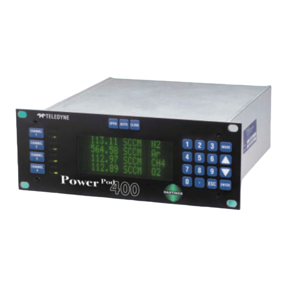
3.0 Features The POWER -400 serves as a convenient control center that can be rack-mounted using standard half- rack hardware or can be used as a bench top unit. The POWER -400 is equipped with a 4 X 20 character, vacuum fluorescent display (VFD). The display emulates a liquid crystal display in its command structure but the VFD gives the unit a greater viewing angle and better visibility than available with most conventional LED or LCD displays. - Page 8 POWER SELECTION Power input is switchable between 100 VAC, 115 VAC and 230VAC (50 or 60 Hz) via the rear panel. For the safety of the operator as well as the device, the correct power level should be selected prior to connecting to the power mains. See the table “POWERPOD-400 Specifications”...
-
Page 9: Specifications
4.0 Specifications Power -400 Specifications Table Specification Value Units Notes Power Inputs 0.7 A, 250VAC, SB Fuse 0.6 A, 250VAC, SB Fuse 0.315 A, 250VAC, SB Fuse 50 -60 Transducer Number Channels Bi-polar Supply Bi-polar Supply 0 - 5 0 - 10 4 - 20 mADC Display... -
Page 10: Front Panel
5.0 Front Panel OPEN CLOSE OPEN CLOSE OPEN CLOSE OPEN CLOSE HASTINGS CHANNEL NUMBER SELECT KEYS Selects channel for editing. An asterisk (*) appears in the first column of the display to indicate that this is the channel to be edited. OVERRIDE INDICATORS Indicates when a channel’s command signal is overridden high (OPEN) or low (CLOSED). -
Page 11: Rear Panel
6.0 Rear Panel POWER ON/OFF SWITCH POWER INLET & FUSE POWER SELECTOR SWITCH FUSE Vs. POWER SETTING TABLE RS-232 SERIAL PORT CONNECTOR (J6) RS-485, DAISY CHAINED, SERIAL PORT CONNECTORS (J7, J9) TRANSDUCER CONNECTORS (J1-J4) ANALOG OUTPUT (J5) ALARMS (J8) Page 11 of 42... -
Page 12: Wiring
7.0 Wiring 7.1. POWER Power is supplied through a fused, AC jack on the rear panel (item 2).Use the power cord supplied with the unit (PN15-17-011 for 115 VAC, 60Hz). See the following table for selecting the proper fuse rating. Use a metric, 5 x 20 mm sized, time-delayed fuse. Power Setting (50 –... -
Page 13: Transducer Connections
7.3. TRANSDUCER CONNECTIONS Connector s J1, 2, 3 and 4 (Item 7) are 15 pin D style connectors wired in the standard Hastings Instruments pin-out (H pin-out). J1, J2, J3, J4 Valve Cntrl Voltage mA Sig mA Sig Sig. Com. Sig. -
Page 14: Analog Signal Followers
7.5. ANALOG SIGNAL FOLLOWERS Analog signals from each channel’s transducers are available for reading or for sending to another power supply for ratio (Master/Slave) operation. The signal can be sent to a channel on another power supply and programmed as a Master for that power supply, allowing the remaining three channels to operate as slaves. -
Page 15: Manual Operation
8.0 Manual Operation 8.1. POWER ON/OFF The Power On switch, item 1 in rear panel drawing, is located in the upper right corner of the rear panel. Insure that the proper power setting is selected prior to turning the power on. See the Power section of WIRING THE POWER -400, above. -
Page 16: Setting A Channel To Auto Control
8.5. SETTING A CHANNEL TO AUTO CONTROL Press the desired CHANNEL # key. An asterisk appears in the first space on the line representing the selected channel. The meter display is immediately replaced with the current set point. Pressing the AUTO key causes pin number eight (8) of the 15 pin Sub-D connector to float and returns the previously programmed metering function to the display. - Page 17 Example (See Graph): A linear flow transducer with a DC output of 0 to 5 volts is calibrated for a maximum flow of 25 SLH. The transducer is connected to one channel of a POWER -400 which is CAL’d to read 25.000 at 5 volts input and has been programmed to display rate in SLH.
-
Page 18: External/Remote Operation
9.0 External/Remote Operation 9.1. SELECTING EXTERNAL/REMOTE OPERATION (Front Panel Only) The POWER -400 allows the user to select different methods of serial communication and control. The following text describes how to choose and activate the desired method. Further information and instructions on how conditions may be changed can be found in section 10, SETUP/CAL mode. -
Page 19: Setup/Cal Mode
10.0 Setup/Cal Mode 10.1. ENTERING THE SETUP/CAL MODE Pressing the MODE key causes the MODE menu to be displayed. Choose the SETUP/CAL mode by pressing the number “3” key then ENTER. A CHANNEL SELECT menu is presented on the display. It should be noted that, although the user must select a specific channel number, some choices in the following menus may affect the operation of all channels and/or the display (ex;... -
Page 20: Selecting Unit-Of-Measure
10.2.3. Selecting Unit-of-Measure After entering the SETUP/CAL mode and after selecting a channel number, the SETUP/CAL menu is displayed. Choose DISPLAY (1) + ENTER and then select UNITS by pressing the number “2” key + ENTER. The UNITS menu will be displayed allowing the selection of over 50 different units of measure (UOM) simply by pressing the number key corresponding to the desired UOM. -
Page 21: Front Panel Lock Out
After SETUP/CAL is selected and a channel number has been chosen, the SETUP/CAL menu is displayed. choose DISPLAY by pressing the number “1” key + ENTER. The FILTER option can be reached by scrolling down once to view the selection number and then pressing the “4” key + ENTER. -
Page 22: Count Down From A Set Point
10.3.2. Count Down from a Set Point The TOTALIZER will be set to count from a preset value to zero (0). When zero is reached, a memory flag will be set to its logic high state. This flag is readable only through serial communications. -
Page 23: Selecting The Analog Signal Level
The default address as programmed at the factory is 01. If a different address is required, it may be changed using either RS-232 or 485. After making the proper serial connections, use the command *00X to read the default address. Use *00Xdd, where dd = the new address. If the old address is known, use DDXdd, where DD is the old address and dd is the new address. -
Page 24: Setting Limit Alarms
10.6. SETTING LIMIT ALARMS Each channel of the POWER 400 has one high limit alarm and one low limit alarm. Each alarm is provided by an open-collector, opto-isolated signal at a corresponding pin on the rear panel, connector J8. Use the provided diagram when referring to the text below. -
Page 25: Setting Ratio Control Parameters
10.7. SETTING RATIO CONTROL PARAMETERS Enabling Ratio Control Ratio control is achieved through the SETUP/CAL menu. Ratio Control is activated by selecting channel number one (1) and enabling it as master. After enabling channel one, the operator may assign the channels that will follow its signal by some factor. -
Page 26: Calibrating A Channel To Its Incoming Signals
10.8. CALIBRATING A CHANNEL TO ITS INCOMING SIGNALS The POWER -400 is designed to accept the input from almost any transducer that operates in the ranges of zero to five volts, zero to ten volts or four to twenty milliamps. In most cases, transducers are capable of having their minimum signal and maximum signal adjusted to correspond with the minimum (ZERO) and maximum (SPAN) unit-of-measure that they are designed to reflect. -
Page 27: Resetting Zero And Span
signal is not an acceptable full range value, the operator has an opportunity to correct any problems at this stage prior to pressing ENTER. Alternatively, the operator can press ESC to exit SETUP/CAL and return later. See Appendix D. 10.8.3. Resetting Zero and Span Should it be required to zero and set a new span value for a given channel, The menu option is provided that will present the programmer with the zero menu first, followed by the span, or cal, menu. -
Page 28: Serial Communication
10.9. SERIAL COMMUNICATION Follow the instructions in the section, WIRING THE POWER -400 for cabling and proper pin out for serial communication with the unit. After insuring that the POWER -400 is wired properly, the unit must be set up following the instructions in the section entitled, External Communications Setup. The instruction set for the POWER -400 can be divided into two different types. - Page 29 To query the status of the totalizer flag on channel four (4), use the following command. TF4Cr The response will be either TF4 0 corresponding to a Boolean ‘FALSE’ indication that the totalizer flag has not been set, or TF4 1, a Boolean ‘TRUE’, indicating that the total is equal to or beyond the totalizer set point..
-
Page 30: Appendix A
11.0 Appendix A Power -400 Serial Commands Command Name Query Response Channel 1 Display CH1 ddd.dd U of M GasID Channel 2 Display CH2 ddd.dd U of M GasID Channel 3 Display CH3 ddd.dd U of M GasID Channel 4 Display CH4 ddd.dd U of M GasID CH1 ddd.dd U of M GasID CH2 ddd.dd U of M GasID... - Page 31 APPENDIX A (Cont.) Power -400 Serial Commands (Cont'd) Command Name Query Response D1<d > Ch1 Disp Mode D1 d note 5 D2<d> Ch2 Disp Mode D2 d D3<d > Ch3 Disp Mode D3 d D4<d > Ch4 Disp Mode D4 d T1S<dddddd>...
- Page 32 APPENDIX A (Notes:) 1. All returned values will include decimal points wherever unit has been programmed to display them. 2. All Commands needing decimal points must include them wherever they are intended to be displayed. 3. d = decimal digit (ASCII) 4.
-
Page 33: Appendix B
12.0 13.0 Appendix C Appendix B Units-of-Measure for Meter Reading & Corresponding Totalizer Units Name Rate Total Name Rate Total 1 Standard Cubic Centimeters per Minute SCCM 35 Standard Cubic Inches per Minute SCIM 2 Standard Liters per Minute 36 Normal Cubic Inches per Minute NCIM 3 Percent 37 Standard Cubic Inches per Second... - Page 34 Gas ID Table (Page 1 of 2) GAS NAME Symbol GAS NAME Symbol GAS NAME Symbol Acetic Acid Diethyl Ether Hydrogen Cyanide Acetic Acid, Anhydride Diethyl Sulfide Hydrogen Fluoride Acetone Difluoroethylene Hydrogen Iodide Acetonitryl Dimethylamine Hydrogen Selenide Acetylene Dimethyl Ether Hydrogen Sulfide Dimethyl Sulfide Isobutane...
- Page 35 Gas ID Table (Page 2 of 2) GAS NAME Symbol GAS NAME Symbol GAS NAME Symbol Pentane R143 R143 Toluene Perchloryl Fluoride ClFO R143A R143A Transbutene Perfluorocyclobutane R152A R152A Trichloroethane R116 R218 Trichloroethylene Perfluoropropane R1416 R1416 R113 R113 Phenol Radon Triethylamine Phosgene COCl...
-
Page 36: Appendix D
14.0 Appendix D Setting the Zero & Span on the Power -400 Power Supply/Totalizer All procedures outlined in this document must be performed with the power supply turned on and warmed up for at least one hour. All procedures outlined in this document must be performed with NO transducers connected to the channel being adjusted You CANNOT successfully zero a channel without, first, supplying zero volts or four milliamps to the meter input for that channel. - Page 37 14.2 Zeroing Unit (4 to 20 mA Range) The following instructions explain how to use the POWER -400 command signal to supply 4mAmp signal to a channel’s input and set the display to read zero at this current level. Disconnect all connectors from the channel to be calibrated. Insure that the channel is set to read 4 to 20 mA signals by performing the following steps.
- Page 38 14.3 Spanning Unit. The following instructions explain how to use the POWER -400 command signal to supply a given channel’s input with the proper span voltage and to set the display to read a transducer’s span value. You must know four things prior to setting the display’s span value: 1.
- Page 39 An example of one possible transducer/ POWER -400 combination. TRANSDUCER POWER -400 Max value to be Max signal out Multiplier Current Span Value displayed 5 VDC 250.00 1.0000 100.00 Setting the THPS-400 Analog level to correspond with the transducer to be attached. Press MODE Press 3 Press ENTER...
- Page 40 Congratulations! You have just calibrated your Power -400 to read zero at zero volts and the transducer’s max display value at the transducer’s max signal input. The only thing left to do is to insure that your transducer is calibrated and that it is wired correctly to the Power -400 .
-
Page 41: Drawings
15.0 Drawings Page 41 of 42... -
Page 42: Warranty
16.0 Warranty 16.1. Warranty Repair Policy Hastings Instruments warrants this product for a period of one year from the date of shipment to be free from defects in material and workmanship. This warranty does not apply to defects or failures resulting from unauthorized modification, misuse or mishandling of the product.
Need help?
Do you have a question about the Power Pod 400 and is the answer not in the manual?
Questions and answers