Table of Contents
Advertisement
Quick Links
Advertisement
Table of Contents

Related Manuals for Acer Aspire S3-391


Summary of Contents for Acer Aspire S3-391
- Page 1 Aspire S3 MS2346 SERVICEGUIDE...
-
Page 2: Revision History
Copyright © 2011 by Acer Incorporated. All rights reserved. No part of this publication may be reproduced, transmitted, transcribed, stored in a retrieval system, or translated into any language or computer language, in any form or by any means, electronic, mechanical, magnetic, optical, chemical, manual or otherwise, without the prior written permission of Acer Incorporated. - Page 3 Conventions The following conventions are used in this manual: WARNING: Indicates a potential for personal injury. CAUTION: Indicates a potential loss of data or damage to equipment. IMPORTANT: Indicates information that is important to know for the proper completion of a procedure, choice of an option, or completing a task.
- Page 4 Acer-authorized Service Providers: Your Acer office may have a different part number code than those given in the FRU list in this service guide. You must use the list provided by your regional Acer office to order FRU parts for repair and service of customer machines.
-
Page 5: Table Of Contents
Aspire S3 MS2346 CHAPTER 1 Hardware Specifications Features ..........1-3 Operating System . - Page 6 BIOS Flash Utilities ........2-12 DOS Flash Utility ........2-13 WinFlash Utility .
- Page 7 Replacing the WLAN Board......3-50 Replacing the M-SATA Board......3-51 Replacing the RTC Battery .
- Page 8 CHAPTER 5 Jumper and Connector Locations Mainboard Layout ........5-3 Clearing Password Check and BIOS Recovery .
-
Page 9: Hardware Specifications
CHAPTER Hardware Specifications... - Page 10 Features ..........1-5 Operating System .
-
Page 11: Features
Hardware Specifications and Configurations Features The following is a summary of the computer’s many features. Operating System ® Genuine Windows 7 Home Premium 64-bit ® Genuine Windows 7 Home Basic 64-bit Platform Huron River platform Supports the Second Generation Intel® Core™ Mobile Processor (Sandy Bridge) ®... -
Page 12: Storage Subsystem
1.3 MP HD webcam Acer Video Conference software, featuring: Acer Crystal Eye webcam with 1280×1024 resolution Acer Video Conference Manager featuring Video Quality Enhancement (VQE) technology Supports 720p HD audio/video recording Wireless and networking WLAN: ... -
Page 13: Power Adapter And Battery
ACPI 3.0-compliant power management system ENERGY STAR compliant Keyboard and Pointing Device Keyboard 84-/85-/88-key full-size Acer FineTip keyboard with international language support Overlay numeric keys Inverted “T” cursor keys Hotkeys for volume and brightness level, media playback, wireless and sleep functions, and display and touchpad toggle ®... -
Page 14: Software And Tools
(except China, Hong Kong) Multimedia Acer clear.fi NTI Media Maker™ Gaming ® Acer Games powered by WildTangent (except China, Hong Kong, Japan, Korea) Communication and ISP Acer Crystal Eye Acer Video Conference Manager ® ... -
Page 15: Warranty
Web links and utilities Acer Accessory Store (Belgium, France, Germany, Italy, Netherlands, Spain, Sweden, UK only) Acer Identity Card Acer Registration Acer Updater ® eBay shortcut (Australia, Austria, Belgium, Canada, France, Germany, Italy, India, Ireland, Netherlands, Norway, Philippines, Poland, Russia, Singapore, Spain, Switzerland, Thailand, US, UK only) ... -
Page 16: Notebook Tour
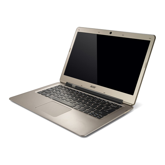
Notebook Tour This section provides an overview of the features and functions of the notebook. Open Front View Figure 1-1. Open Front View Table 1-1. Open Front View Icon Item Description Integrated webcam Web camera for video communication. Display screen Also called liquid crystal display (LCD), displays computer output. -
Page 17: Rear View
Rear View Figure 1-2. Rear View Table 1-2. Rear View Icon Item Description DC-in jack Connects to the AC adapter. HDMI port Supports high definition digital video connections. USB 2.0 ports Connects to USB devices (e.g., USB mouse, USB camera). Battery indicator Indicates the computer’s battery status. -
Page 18: Left View
Left View Figure 1-3. Left View Table 1-3. Left View Icon Item Description Headphone/Mic in Connects to combo Headphone/Mic in devices combo jack 1-10 Hardware Specifications and Configurations... -
Page 19: Right View
Right View Figure 1-4. Right View Table 1-4. Right View Icon Item Description 2-in-1 card reader Supports MMC, MMCplus, and SD cards. Note: Only one card can operate at any given time. 1-11 Hardware Specifications and Configurations... -
Page 20: Base View
Base View Figure 1-5. Base View Table 1-5. Base View Icon Item Description Battery reset pinhole Insert a paperclip into the hole and press for four seconds to reset the computer (simulates removing and reinstalling the battery) Strap Slot For optional strap accessory. Speakers Deliver stereo audio output. -
Page 21: Touchpad Basics
Touchpad Basics Figure 1-6. Touchpad Move finger across the multi-touchpad (1) to move the cursor. Tapping on the multi-touchpad is the same as clicking the left button of a mouse. Press the lower left (2) and lower right (3) part of the multi-touchpad to perform selection and execution functions. -
Page 22: Keyboard
Keyboard The keyboard contains an overlay numeric keys, inverted “T” cursor key, Windows® key, Application key, function lock keys, and hotkeys controlling various computer features. Figure 1-7. Keyboard Lock Keys The keyboard has three lock keys which the user can toggle on and off. Figure 1-8. -
Page 23: Windows Keys
Table 1-8. Keyboard Lock Keys Lock Key Description Num Lock The key can be turned on/off via the internal keyboard (Fn+F11) or the external keyboard/keypad. Num Lock affects the external Fn+F11 keyboard/keypad only. Shift state is NOT required for the cursor movement by the numeric ... - Page 24 Table 1-9. Windows-specific Keys Description Windows Ctrl+ +L: Lock your computer (if you are connected to a network domain), or switch users (if you're not connected to a network domain) Logo key Ctrl+ +Tab: Moves focus from Start menu, to the Quick Launch ...
- Page 25 Table 1-10. Hotkeys Hotkey Icon Function Description Fn+F8 Speaker toggle Turns the speakers On or Off. Fn+ Volume Up Increases the sound volume. Fn+ Volume Down Decreases the sound volume. Fn+ Brightness Down Decreases the screen brightness. Fn+ Brightness Up Increases the screen brightness.
-
Page 26: D2D Recovery
D2D Recovery The Acer Disk to Disk (D2D) recovery function allows you to use the recovery partition to troubleshoot your computer. 1. Restart the computer. 2. During POST, press F1 to access the BIOS Setup screen. 3. Press to select the Main menu. -
Page 27: Specification Tables
Specification Tables Computer Specifications Item Metric Imperial Dimensions Width 32.2 cm 12.68 in Depth 21.85 cm 8.52 in Height 1.75 cm 0.68 in Weight (equipped with 3-cell 1.33 kg with SSD disk drive 2.93 lbs battery pack) 1.35 kg with HDD disk drive 2.98 lbs Input power Operating voltage... - Page 28 System Board Item Specification Core logic ® Mobile Intel HM77 (6MB BIOS ROM) Chipset Graphics ® UMA: Integrated in the Intel Core™ Mobile Processor USB 2.0 ® Integrated in the Mobile Intel HM65 Express Chipset Wireless LAN Foxconn BCM 43225 ...
- Page 29 CPU Temperature Fan Speed (RPM) SPL Spec (dBA) 5700 6200 6500 Throttling 50%: On= 85 °C; OFF=84 °C OS shuts down at 97 °C; Hardware shuts down at 85 °C System Memory Item Specification Memory controller ® Integrated in the Intel Core™...
- Page 30 Keyboard Item Specification Type Aspire AF1S Flat keyboard Total number of keys 84 keys Windows logo key Internal and external USB keyboard work simultaneously? Features Overlay numeric keys Inverted “T” cursor keys Hotkeys for volume and brightness level, media playback, ...
- Page 31 Item Specification Power Requirement 5 VDC Solid State Drive (SSD) Item Specification Vendor and A-DATA SSD NAND AS511S7-120GM A-DATA SSD NAND models AS511S7-240GM Product series A-DATA SSD NAND AS511S7 Configuration Interface Serial ATA-6Gb/s Capacity (GB) Performance Max. Read Speed 550MB / s 550MB / s Max.
- Page 32 Item Specification Response time Typical 8 ms Maximum 16 ms Typical power consumption (watt) Electrical interface 1-channel LVDS Backlight White LED (WLED) Weight 310 g Physical size 306.8 × 189.2 × 3.6 mm Supported Display Resolutions Specification 800×600, 60 Hz, 16:9 1024×768, 60 Hz, 16:9 1280×600, 60 Hz, 16:9 1280×720, 60 Hz, 16:9...
- Page 33 Item Specification Compatibility High Definition Audio Specification Sampling rate 1 Hz resolution VSR (Variable Sampling Rate) Internal microphone Internal speaker/quantity Yes, two speakers Webcam Item Specification Vendor and models Lite-On HD_S LT_119_SP Primax PM_S119_SP Suyin SY_S119_SP Resolution 1.3 MP HD Wireless LAN Item...
- Page 34 Item Specification Data throughput Up to 16.7 million colors Number of HDMI port Location Back System LED Indicators Item Specification Power status Solid blue: The computer is turned on. Blinking amber: The computer is in power-saving mode. Indicator off: The computer is turned off. ...
- Page 35 Item Specification Power global states G3 Mechanical Off - This off state is entered through a mechanical means; no electrical current is running through the circuitry and it can be worked on without damaging the hardware or endangering service personnel. Except for the real-time clock, power consumption is zero.
- Page 36 System DMA Specification Legacy Mode Power Management DMA0 Free DMA1 Free DMA2 Free DMA3 Free DMA4 Direct memory access controller DMA5 Free DMA6 Free DMA7 Free System Interrupt Specification Hardware IRQ System Function IRQ0 System timer IRQ1 Standard PS/2 keyboard IRQ2 Not in use IRQ3...
- Page 37 System IO Address Map I/O address (hex) System Function (shipping configuration) 0000 - 001F Direct Memory Access Controller 0000- 0CF7 PCI bus 0020- 0021 Programmable Interrupt Controller 0024- 0025 Programmable Interrupt Controller 0028- 0029 Programmable Interrupt Controller 002C - 002D Programmable Interrupt Controller 002E - 002F Motherboard resources...
- Page 38 I/O address (hex) System Function (shipping configuration) 00AC - 00AD Programmable Interrupt Controller 00B0- 00B1 Programmable Interrupt Controller 00B2- 00B3 Motherboard resources 00B4- 00B5 Programmable Interrupt Controller 00B8- 00B9 Programmable Interrupt Controller 00BC - 00BD Programmable Interrupt Controller 00C0- 00DF Direct Memory Access Controller 00C0- 00F0 Numeric data processor...
-
Page 39: System Utilities
CHAPTER System Utilities... - Page 40 BIOS Setup Utility ........2-3 Navigating the BIOS Utility .
-
Page 41: Bios Setup Utility
System Utilities BIOS Setup Utility This utility is a hardware configuration program built into a computer’s BIOS (Basic Input/Output System). The utility is pre-configured and optimized so most users do not need to run it. If configuration problems occur, the setup utility may need to be run. Refer to Chapter 4, Troubleshooting when a problem arises. -
Page 42: Bios Menus
BIOS Menus This section describes the InsydeH2O BIOS Setup Utility menu tabs. NOTE: NOTE: The screenshots used in this chapter are for reference only. Actual values can vary depending on the computer model. Information This tab shows a summary of the computer‘s hardware information. Figure 2-1. - Page 43 Table 2-1. Hardware Information (Continued) Parameter Description Product Name Model name of the computer Manufacturer Name Computer manufacturer UUID The universally unique identifier tag assigned to the computer System Utilities...
- Page 44 Main Use this tab to set the system time and date, enable or disable boot options, and enable or disable the D2D recovery feature. Figure 2-2. BIOS Main Table 2-2. BIOS Main Parameter Description Format/Option System Time System time expressed in 24-hour format Format: HH:MM:SS (hour:minute:second) System Date...
- Page 45 Security Use this tab to safeguard and protect the computer from unauthorized use. Figure 2-3. BIOS Security Table 2-3. BIOS Security Parameter Description Option Supervisor Password Is Supervisor password setting or Set Clear User Password Is User password setting or Set Clear HDD Password State Hard drive password setting...
-
Page 46: Setting A Password
Setting a Password Follow the succeeding instructions to set the user or supervisor passwords. 1. Press to highlight a Set _______ Password parameter and press Enter. The Set _______ Password dialog box appears. Set Supervisor Password Enter New Password Confirm New Password [ Figure 2-4. -
Page 47: Changing A Password
Changing a Password 1. Press to highlight a Set _______ Password parameter and press Enter. The Set _______ Password dialog box appears. Set Supervisor Password Enter Current Password [ Enter New Password [ Confirm New Password [ Figure 2-6. Set Supervisor Password 2. - Page 48 Boot Use this tab to set the preferred drive sequence in which the Setup Utility attempts to boot the operating system. By default, the computer searches for boot devices in the following order: 1. Hard disk drive 2. External USB bootable device 3.
- Page 49 Exit Use the Exit tab to save or discard changes and close the BIOS Setup Utility. Figure 2-9. BIOS Exit Table 2-4. Exit Parameters Parameter Description Exit Saving Changes Close the BIOS Setup Utility and save the setup changes. Exit Discarding Changes Close the BIOS Setup Utility without saving the setup changes.
-
Page 50: Bios Flash Utilities
BIOS Flash Utilities BIOS Flash memory updates are required for the following conditions: New versions of system programs New features or options Restore a BIOS when it becomes corrupted. Use the Flash utility to update the system BIOS Flash ROM. NOTE: NOTE: If a Crisis Recovery Disc is not available, create one before Flash utility is used. -
Page 51: Dos Flash Utility
DOS Flash Utility Perform the following to use the DOS Flash Utility: 1. Press F2 during boot to enter Setup Menu. 2. Select Boot Menu to modify boot priority order. Example: If using USB HDD to Update BIOS, move USB HDD to position 1. Figure 2-10. -
Page 52: Remove Hdd/Bios Password Utilities
Remove HDD/BIOS Password Utilities This section explains how to remove the HDD and BIOS passwords. Removing the HDD Password NOTE: NOTE: If the incorrect HDD password is entered three times in succession, an error is generated. (Figure 2-11) Password Error Status HDD password error code Figure 2-11. -
Page 53: Removing The Bios Passwords
Removing the BIOS Passwords To clear a lost BIOS password (user or supervisor password), you need to short the clear password hardware gap (G2201) located on the mainboard. Refer to the “Clearing the BIOS Passwords” on page section for detailed instructions. Figure 2-14. -
Page 54: Using Dmi Tools
Using DMI Tools The DMI (Desktop Management Interface) Tool copies BIOS information to EEPROM (Electrically Erasable Programmable Read-Only Memory). Used in the DMI pool for hardware management. LAN EEPROM Utility LAN EEPROM Utility enables to change the MAC address. Perform the following steps to use the LAN EEPROM Utility: 1. -
Page 55: Machine Maintenance
CHAPTER Machine Maintenance... - Page 56 Machine Disassembly and Replacement ....3-3 Recommended Equipment ......3-3 Replacement Requirements .
- Page 57 Replacing the Battery Pack ......3-71 Replacing the Lower Case......3-74...
-
Page 59: Machine Disassembly And Replacement
Machine Maintenance Machine Disassembly and Replacement This chapter contains step-by-step procedures on how to disassemble the notebook computer for maintenance and troubleshooting. Cable paths and positioning may not represent the actual model. During the removal and installation of the components, ensure all available cable channels and clips are used and that the cables are replaced in the same position. -
Page 60: Pre-Disassembly Instructions
Pre-disassembly Instructions Before proceeding with the disassembly procedure, make sure that you do the following: 1. Turn off the power to the system and all peripherals. 2. Unplug the AC adapter and all power and signal cables from the system. Figure 3-1. -
Page 61: Disassembly Process
BOARD MIDDLE KEYBOARD COVER MODULE Figure 3-2. Disassembly Flowchart Table 3-2. Screw List Step Screw Quantity Acer Part Number Lower Case Disassembly M2 x L4.5 86.EA552.4R5 Battery Pack Disassembly M2 x L4.5 86.EA552.4R5 Speaker Module Disassembly M1.4 x L3 86.EA36N.3R0... - Page 62 Table 3-2. Screw List Step Screw Quantity Acer Part Number Mainboard Disassembly M2 x L3 86.00E14.523 RTC Battery Disassembly WLAN Board Disassembly Keyboard Disassembly M1.4 x L1.2 86.EA322.2R0 Middle Cover Disassembly M2 x L3 86.00E14.523 LCD Module Disassembly M2 x L4.5 86.EA552.4R5...
-
Page 63: Removing The Lower Case
Removing the Lower Case 1. Remove the twelve screws securing the lower case. Figure 3-3. Lower Case Screws Table 3-3. Screws Step Screw Quantity Screw Type Lower Case Disassembly M2 x L4.5 2. Gently lift the lower case and lay it down beside the main unit. Figure 3-4. -
Page 64: Removing The Battery Pack
Removing the Battery Pack 1. Perform the “Removing the Lower Case” procedure described on page 3-9. 2. Remove the two screws securing the left speaker to the upper case. Figure 3-5. Left Speaker Screws Table 3-5. Screws Step Screw Quantity Screw Type Left Speaker Module Disassembly M1.4 x L3... - Page 65 4. Lift the DC-In & Power cable off the battery pack. Figure 3-7. DC-In & Power Cable 5. Remove the two screws securing the battery pack to the upper case. Figure 3-8. Battery Pack Screws Table 3-8. Screws Step Screw Quantity Screw Type Battery Pack Disassembly...
- Page 66 6. Lift the battery pack off its socket in the upper case then slide it a few millimeters away from the mainboard (1). Disconnect the battery cable from the WLAN board (2). Figure 3-9. Battery Cable 7. Detach the battery pack from the upper case. Figure 3-10.
-
Page 67: Removing The Left And Right Speakers
Removing the Left and Right Speakers 1. Perform the “Removing the Lower Case” procedure described on page 3-9. 2. Perform the “Removing the Battery Pack” procedure described on page 3-10. 3. Remove the two screws securing the right speakers to the upper case (1). Figure 3-11. - Page 68 6. Disconnect the speaker’s cable from the mainboard. Figure 3-13. Speaker Cable 3-14 Machine Maintenance...
-
Page 69: Removing The Wlan Module
Removing the WLAN Module 1. Perform the “Removing the Lower Case” procedure described on page 3-9. 2. Perform the “Removing the Battery Pack” procedure described on page 3-10. 3. Unplug the two antenna cables from the WLAN module. Figure 3-14. WLAN Module Antennas IMPORTANT: For reference during machine reassembly, note which cable color corresponds to the main (black) and auxiliary (white) connectors. - Page 70 5. Remove the screw securing the WLAN module to the WLAN/M-SATA board. Figure 3-16. WLAN Module Screw Table 3-16. Screw Step Screw Quantity Screw Type WLAN Module Disassembly M2 × L3 6. Detach the WLAN module from the slot. Figure 3-17. WLAN Module NOTE: NOTE: A circuit board that is >...
-
Page 71: Removing The Dc-In Module (Wlan Board)
Removing the DC-In Module (WLAN Board) NOTE: NOTE: For models that have M-SATA board installed, please proceed to page 3-18, “Removing the DC-In Module (M-SATA Board)” 1. Perform the “Removing the Lower Case” procedure described on page 3-9. 2. Perform the “Removing the Battery Pack”... -
Page 72: Removing The Dc-In Module (M-Sata Board)
Removing the DC-In Module (M-SATA Board) 1. Perform the “Removing the Lower Case” procedure described on page 3-9. 2. Perform the “Removing the Battery Pack” procedure described on page 3-10. 3. Disconnect the DC-In cable from the M-SATA board & the mainboard (1) then release the DC-In cable from the self adhesive tape securing it (2). -
Page 73: Removing The Hdd Module
Removing the HDD Module NOTE: NOTE: For models that have SSD disk drive installed, please proceed to page 3-22, “Removing the SSD Module”. 1. Perform the “Removing the Lower Case” procedure described on page 3-9. 2. Perform the “Removing the Battery Pack”... - Page 74 5. Remove the screw securing the HDD module to the upper case. Figure 3-24. HDD Module Screw Table 3-24. Screw Step Screw Quantity Screw Type HDD Module Disassembly M2 x L3 6. Detach the HDD module from the upper case. Figure 3-25.
- Page 75 7. Detach the cable from the HDD module. Figure 3-26. HDD Cable 8. Remove the four screws securing the HDD module to the bracket (1) then detach the HDD module from the bracket (2). Figure 3-27. HDD Bracket Screws Table 3-27. Screws Step Screw Quantity...
-
Page 76: Removing The Ssd Module
Removing the SSD Module 1. Perform the “Removing the Lower Case” procedure described on page 3-9. 2. Perform the “Removing the Battery Pack” procedure described on page 3-10. 3. Release the SSD cable from the adhesive tape securing it. Figure 3-28. SSD Cable Adhesive Tape 4. - Page 77 5. Remove the screw securing the SSD module to the upper case. Figure 3-30. SSD Module Screw Table 3-30. Screw Step Screw Quantity Screw Type SSD Module Disassembly M2 x L3 6. Detach the SSD module from the upper case. Figure 3-31.
- Page 78 7. Detach the cable from the SSD module. Figure 3-32. SSD Cable 8. Remove the four screws securing the SSD module to the bracket (1) then detach the SSD module from the bracket (2). Figure 3-33. SSD Bracket Screws Table 3-33. Screws Step Screw Quantity...
-
Page 79: Removing The Card Reader Board
Removing the Card Reader Board 1. Perform the “Removing the Lower Case” procedure described on page 3-9. 2. Perform the “Removing the Battery Pack” procedure described on page 3-10. 3. Disconnect the card reader cable from the mainboard and the card reader board. Figure 3-34. - Page 80 5. Detach the card reader board from the upper case. Figure 3-36. Card Reader Board NOTE: NOTE: A circuit board that is > 10cm has been highlighted with a yellow rectangle in Figure 3-36. Follow the local regulations for disposing this type of circuit board. 3-26 Machine Maintenance...
-
Page 81: Removing The Mainboard
Removing the Mainboard 1. Perform the “Removing the Lower Case” procedure described on page 3-9. 2. Perform the “Removing the Battery Pack” procedure described on page 3-10. 3. Release the connector latch (1) from the mainboard, then disconnect the touchpad cable (2). Figure 3-37. - Page 82 5. Release the connector latch (1) from the mainboard, then disconnect the power button cable (2). Figure 3-39. Power Button Cable 6. Release the latch (1) from the mainboard then disconnect the keyboard cable (2). Figure 3-40. Keyboard Cable 3-28 Machine Maintenance...
- Page 83 7. Release the LCD cable from the adhesive tape securing it. Figure 3-41. LCD Cable Adhesive Tape 8. Disconnect the LCD cable from the mainboard. Figure 3-42. LCD Cable 3-29 Machine Maintenance...
- Page 84 9. Remove the screw securing the mainboard to the upper case. Figure 3-43. Mainboard Screw Table 3-43. Screw Step Screw Quantity Screw Type Mainboard Disassembly M2 × L3 10. Detach the mainboard from the upper case. Figure 3-44. Mainboard NOTE: NOTE: A circuit board that is >...
-
Page 85: Removing The Thermal Module
Removing the Thermal Module 1. Perform the “Removing the Lower Case” procedure described on page 3-9. 2. Perform the “Removing the Battery Pack” procedure described on page 3-10. 3. Disconnect the thermal module fan cable from the mainboard. Figure 3-45. Fan Cable 4. - Page 86 5. Detach the thermal module from the mainboard. Figure 3-47. Thermal Module 3-32 Machine Maintenance...
-
Page 87: Removing The Rtc Battery
Removing the RTC Battery 1. Perform the “Removing the Lower Case” procedure described on page 3-9. 2. Perform the “Removing the Battery Pack” procedure described on page 3-10. 3. Perform the “Removing the Mainboard” procedure described on page 3-27. 4. Disconnect the RTC battery cable from the mainboard. Figure 3-48. -
Page 88: Removing The Wlan Board
Removing the WLAN Board NOTE: NOTE: For models that have M-SATA board installed, please proceed to page 3-35, “Removing the M-SATA Board”. 1. Perform the “Removing the Lower Case” procedure described on page 3-9. 2. Perform the “Removing the Battery Pack”... -
Page 89: Removing The M-Sata Board
Removing the M-SATA Board 1. Perform the “Removing the Lower Case” procedure described on page 3-9. 2. Perform the “Removing the Battery Pack” procedure described on page 3-10. 3. Perform the “Removing the WLAN Module” procedure described on page 3-15. 4. -
Page 90: Removing The Keyboard
Removing the Keyboard NOTE: NOTE: The keyboard is easily warped or damaged during the removal process. Take care not to use excessive force when removing. 1. Perform the “Removing the Lower Case” procedure described on page 3-9. 2. Perform the “Removing the Battery Pack”... - Page 91 12. Remove the twenty nine screws securing the keyboard to the upper case. Figure 3-56. Keyboard Screws Table 3-56. Screws Step Screw Quantity Screw Type Keyboard Disassembly M1.4 × L1.2 13. Detach the keyboard from the upper case. Figure 3-57. Keyboard 3-37 Machine Maintenance...
-
Page 92: Removing The Power Button Board
Removing the Power Button Board 1. Perform the “Removing the Lower Case” procedure described on page 3-9. 2. Perform the “Removing the Battery Pack” procedure described on page 3-10. 3. Release the latch (1) from the mainboard then disconnect the power button cable (2). Figure 3-58. -
Page 93: Removing The Middle Cover Assembly
Removing the Middle Cover Assembly 1. Perform the “Removing the Lower Case” procedure described on page 3-9. 2. Perform the “Removing the Battery Pack” procedure described on page 3-10. 3. Perform the “Removing the Left and Right Speakers” procedure described on page 3-13. 4. - Page 94 12. Tilt the upper case until it is approximately at a 100° angle with the LCD assembly. Figure 3-61. Upper Case Assembly 13. Detach the middle cover assembly from the upper case. Figure 3-62. Middle Cover Assembly 3-40 Machine Maintenance...
-
Page 95: Removing The Lcd Module
Removing the LCD Module 1. Perform the “Removing the Lower Case” procedure described on page 3-9. 2. Perform the “Removing the Battery Pack” procedure described on page 3-10. 3. Perform the “Removing the Left and Right Speakers” procedure described on page 3-13. 4. - Page 96 13. Remove the four screws securing the upper case to the LCD hinges. Figure 3-64. Upper Case Screws – LCD Hinges Table 3-64. Screws Step Screw Quantity Screw Type LCD Module Disassembly M2 x L4.5 14. Gently detach the LCD cable from the upper case (1) and lift the upper case away from the LCD module (2).
-
Page 97: Reassembly Process
Reassembly Process Replacing the LCD Module 1. Tilt the LCD hinge approximately at a 45° angle then insert the upper case and align the screw posts of the upper case with the screw holes in the LCD hinges. Figure 3-66. Upper Case 2. - Page 98 3. Secure the upper case to the LCD hinges using four screws. Figure 3-68. Upper Case - LCD Hinge Screws Table 3-68. Screws Step Screw Quantity Screw Type Upper Case Reassembly M2 x L4.5 3-44 Machine Maintenance...
-
Page 99: Replacing The Middle Cover Assembly
Replacing the Middle Cover Assembly 1. Tilt the upper case until it is approximately at a 100° angle with the LCD assembly Figure 3-69. Upper Case Assembly 2. Insert the middle cover assembly in its slot. Figure 3-70. Middle Cover Assembly 3-45 Machine Maintenance... - Page 100 3. Pull the upper case downward until it sits parallel with the LCD assembly. Figure 3-71. Upper Case Assembly 4. Secure the middle cover assembly to the upper case using four screws. Figure 3-72. Middle Cover Assembly Screws Table 3-72. Screws Step Screw Quantity...
-
Page 101: Replacing The Power Button Board
Replacing the Power Button Board 1. Insert the power button board in its slot in the middle cover (1), then secure it using adhesive tapes (2). Figure 3-73. Power Button Board 2. Connect the power button cable to the mainboard (1), then press the connector latch (2) until it locks into place. -
Page 102: Replacing The Keyboard
Replacing the Keyboard 1. Place the keyboard in its slot in the upper case. Figure 3-75. Keyboard 2. Secure the keyboard to the upper case using twenty nine screws. Figure 3-76. Keyboard Screws Table 3-76. Screws Step Screw Quantity Screw Type Keyboard Reassembly M1.4 ×... - Page 103 3. Secure the keyboard to the upper case using adhesive tape. Figure 3-77. Keyboard 4. Fix the LCD cable to the upper case. Figure 3-78. LCD Cable IMPORTANT: Make sure that the LCD cable is installed as highlighted in Figure 3-78 avoid damaging the LCD cable.
-
Page 104: Replacing The Wlan Board
Replacing the WLAN Board NOTE: NOTE: For models that have M-SATA board installed, please proceed to page 3-51, “Replacing the M-SATA Board.”. 1. Place the WLAN board in its slot in the upper case. Figure 3-79. WLAN Board 2. Connect the WLAN & mini 1 cables (1) to the WLAN board, then press the connector latch (2) until it locks into place.Connect the power cable to the WLAN board (3). -
Page 105: Replacing The M-Sata Board
Replacing the M-SATA Board. 1. Place the M-SATA board in its slot in the upper case. Figure 3-81. M-SATA Board 2. Connect the WLAN & mini 1 cables (1) to the M-SATA board, then press the connector latch (2) until it locks into place. Figure 3-82. -
Page 106: Replacing The Rtc Battery
Replacing the RTC Battery 1. Secure the RTC battery to the bottom of the mainboard using self adhesive tape. Figure 3-83. RTC Battery 2. Connect the RTC battery cable to the mainboard. Figure 3-84. RTC Battery Cable 3-52 Machine Maintenance... -
Page 107: Replacing The Thermal Module
Replacing the Thermal Module 1. Place the thermal module in its slot in the mainboard. Figure 3-85. Thermal Module 2. Secure the thermal module using the spring-loaded captive screws. Follow the screw sequence indicated on Figure 3-86. Figure 3-86. Thermal Module Screws Table 3-86. - Page 108 3. Connect the thermal module fan cable to the mainboard. Figure 3-87. Fan Cable 3-54 Machine Maintenance...
-
Page 109: Replacing The Mainboard
Replacing the Mainboard 1. Place the mainboard in its slot in the upper case. Figure 3-88. Mainboard 2. Secure the mainboard to the upper case using one screw. Figure 3-89. Mainboard Screw Table 3-89. Screw Step Screw Quantity Screw Type Mainboard Reassembly M2 ×... - Page 110 3. Connect the LCD cable to the mainboard. Figure 3-90. LCD Cable 4. Secure the LCD cable to the mainboard using adhesive tape. Figure 3-91. LCD Cable Adhesive Tape 3-56 Machine Maintenance...
- Page 111 5. Connect the keyboard cable to the mainboard (1) and then push the connector latch (2) until it locks into place. Figure 3-92. Keyboard Cable 6. Connect the WLAN & mini 1 cables (1) to the mainboard, then press the connector latch (2) until it locks into place.Connect the power cable to the mainboard (3).
- Page 112 7. Connect the touchpad cable to the mainboard (1) and then press the connector latch (2) until it locks into place. Figure 3-94. Touchpad Cable 3-58 Machine Maintenance...
-
Page 113: Replacing The Card Reader Board
Replacing the Card Reader Board 1. Place the card reader board in its slot in the upper case. Figure 3-95. Card Reader Board 2. Secure the card reader board to the upper case using two screws. Figure 3-96. Card Reader Board Screws Table 3-96. - Page 114 3. Connect the card reader cable to the mainboard and the card reader board. Figure 3-97. Card Reader Cable 3-60 Machine Maintenance...
-
Page 115: Replacing The Hdd Module
Replacing the HDD Module NOTE: NOTE: For models that have SSD disk drive installed, please proceed to page 3-64, “Replacing the SSD Module” 1. Place the HDD module in the bracket (1) and then secure the HDD bracket using four screws (2). - Page 116 3. Place the HDD module in its slot in the upper case. Figure 3-100. HDD Module 4. Secure the HDD module to the upper case using one screw. Figure 3-101. HDD Module Screw Table 3-101. Screw Step Screw Quantity Screw Type HDD Module Reassembly M2 x L3 3-62...
- Page 117 5. Connect the HDD cable to the mainboard. Figure 3-102. HDD Cable 6. Secure the HDD cable to the upper case using adhesive tape. Figure 3-103. HDD Cable Adhesive Tape 3-63 Machine Maintenance...
-
Page 118: Replacing The Ssd Module
Replacing the SSD Module 1. Place the SSD module in the bracket (1) and then secure the SSD bracket using four screws (2). Figure 3-104. SSD Bracket Screws Table 3-104. Screws Step Screw Quantity Screw Type SSD Bracket Reassembly M3 x L4 2. - Page 119 3. Place the SSD module in its slot in the upper case. Figure 3-106. SSD Module 4. Secure the SSD module to the upper case using one screw. Figure 3-107. SSD Module Screw Table 3-107. Screw Step Screw Quantity Screw Type SSD Module Reassembly M2 x L3 3-65...
- Page 120 5. Connect the SSD cable to the mainboard. Figure 3-108. SSD Cable 6. Secure the SSD cable to the upper case using adhesive tape. Figure 3-109. SSD Cable Adhesive Tape 3-66 Machine Maintenance...
-
Page 121: Replacing The Dc-In Module (Wlan Board)
Replacing the DC-In Module (WLAN Board) 1. Place the DC-In socket in its slot in the upper case. Figure 3-110. DC-In 2. Connect the DC-In cable to the WLAN board (1) then secure the DC-In cable to the upper case using self adhesive tape (2). Figure 3-111. -
Page 122: Replacing The Dc-In Module (M-Sata Board)
Replacing the DC-In Module (M-SATA Board) 1. Place the DC-In socket in its slot in the upper case. Figure 3-112. DC-In 2. Connect the DC-In cable to the M-SATA board and the mainboard (1) then secure the DC-In cable to the upper case using self adhesive tape (2). Figure 3-113. -
Page 123: Replacing The Wlan Module
Replacing the WLAN Module 1. Insert the WLAN module in its slot in the WLAN board. Figure 3-114. WLAN Module 2. Secure the WLAN module to the upper case using one screw. Figure 3-115. WLAN Module Screw Table 3-115. Screw Step Screw Quantity... - Page 124 3. Secure the antenna cables to the upper case using adhesive tapes. Figure 3-116. Antenna Cables Adhesive Tapes 4. Connect the two antenna cables to the WLAN module. Figure 3-117. WLAN Module Antennas IMPORTANT: Connect the black cable to the main connector and the white cable to the auxiliary connector.
-
Page 125: Replacing The Right Speakers
Replacing the Right Speakers 1. Connect the speaker’s cable to the mainboard. Figure 3-118. Speaker Cable 2. Place the right speaker in its slot in the upper case. Figure 3-119. Speakers 3-71 Machine Maintenance... - Page 126 3. Secure the speaker cable to the upper case using adhesive tapes (1), then secure the right speaker to the upper case using two screws (2). Figure 3-120. Right Speaker Screws and Adhesive Tape Table 3-120. Screws Step Screw Quantity Screw Type Right Speaker Module Reassembly M1.4 x L3...
-
Page 127: Replacing The Battery Pack
Replacing the Battery Pack 1. Slide the battery pack underneath the mini 1 and WLAN/M-SATA cables as shown. Figure 3-121. Battery Pack 2. Connect the battery cable to the WLAN board (1), then push the battery pack forward until its four socket holes fits into the screw posts in the upper case (2). Figure 3-122. - Page 128 3. Secure the battery pack to the upper case using two screws. Figure 3-123. Battery Pack Screws Table 3-123. Screws Step Screw Quantity Screw Type Battery Pack Reassembly M2 x L4.5 4. Secure the DC-In & Power cable to the battery pack surface using self adhesive tapes. Figure 3-124.
- Page 129 5. Place the left speaker in its slot in the upper case. Figure 3-125. Left Speaker 6. Secure the left speaker to the upper case using two screws. Figure 3-126. Left Speaker Screws Table 3-126. Screws Step Screw Quantity Screw Type Left Speaker Module Reassembly M1.4 x L3 3-75...
-
Page 130: Replacing The Lower Case
Replacing the Lower Case 1. Place the lower case into the upper case, making sure the I/O ports of the mainboard are extruding from their port holes. Figure 3-127. Lower Case 2. Secure the lower case using twelve screws. Figure 3-128. Lower Case Screws Table 3-128. -
Page 131: Troubleshooting
CHAPTER Troubleshooting... - Page 132 Introduction ......... .4-3 General Information .
-
Page 133: Introduction
NOTE: NOTE: The diagnostic tests are intended for Acer products only. Non-Acer products, prototype cards, or modified options can give false errors and invalid system responses. 1. Obtain as much detailed information as possible about the problem. -
Page 134: Power On Issues
Power On Issues If the system does not power on, perform the following, one at a time, to correct the problem. Do not replace a non-defective FRU. Figure 4-1. Power On Issue Computer Shuts Down Intermittently If the system powers off at intervals, perform the following. 1. -
Page 135: No Display Issues
No Display Issues If the Display does not work, perform the following, one at a time. Do not replace a non-defective FRU: Figure 4-2. No Display Issue No POST or Video If the POST or video does not appear, perform the following one at a time. 1. -
Page 136: Abnormal Video
3. Drain stored power by removing the power cable and the battery pack. Hold the power button for 10 seconds. 4. Connect the power cable and reboot the computer. 5. Connect an external monitor to the computer and switch between the internal display and the external display by pressing Fn+F5. -
Page 137: Lcd Failure
8. Run the Windows Memory Diagnostic from the operating system DVD and follow the on-screen prompts. 9. If the issue is still not resolved, refer to the Online Support Information on page LCD Failure If the LCD fails, perform the following, one at a time. Do not replace a non-defective FRU: Figure 4-3. -
Page 138: Keyboard Failure
Keyboard Failure If the Keyboard fails, perform the following, one at a time. Do not replace a non-defective FRU: Figure 4-4. Keyboard Failure Troubleshooting... -
Page 139: Touchpad Failure
Touchpad Failure If the Touchpad fails, perform the following, one at a time. Do not replace a non-defective FRU: Figure 4-5. Touchpad Failure Troubleshooting... -
Page 140: Internal Speaker Failure
Internal Speaker Failure If internal Speakers fail, perform the following, one at a time. Do not replace a non-defective FRU: Figure 4-6. Internal Speaker Failure Sound Problems Perform the following, one at a time. 1. Boot the computer. 2. Navigate to Start Control Panel System and Maintenance System Device Manager. - Page 141 Drag the slider to 50. Confirm that the volume is not muted. Click Mixer to verify that other audio applications are set to 50 and not muted. 6. Navigate to Start Control Panel Hardware and Sound Sound. Confirm that Speakers are selected as the default audio device (green check mark).
-
Page 142: Microphone Failure
Microphone Failure If internal or external Microphones fail, perform the following, one at a time. Figure 4-7. Microphone Failure 1. Check that the microphone is enabled. Navigate to Start Control Panel Hardware and Sound Sound and select the Recording tab. 2. -
Page 143: Usb Failure
USB Failure If the USB fails, perform the following, one at a time. Do not replace a non-defective FRU: Figure 4-8. USB Failure 4-13 Troubleshooting... -
Page 144: Wlan Failure
WLAN Failure If the WLAN fails, perform the following, one at a time. Do not replace a non-defective FRU: Figure 4-9. WLAN Failure 4-14 Troubleshooting... -
Page 145: Card Reader Failure
Card Reader Failure If the Card Reader fails, perform the following, one at a time. Do not replace a non-defective FRU: Figure 4-10. Card Reader Failure 4-15 Troubleshooting... -
Page 146: Thermal Unit Failure
Thermal Unit Failure If the Thermal Unit fails, perform the following, one at a time. Do not replace a non-defective FRU: Figure 4-11. Thermal Unit Failure 4-16 Troubleshooting... -
Page 147: Other Functions Failure
Other Functions Failure 1. Check if drives are functioning correctly. 2. Check if external modules are functioning correctly. 3. Change mainboard to check if current one is defective. 4-17 Troubleshooting... -
Page 148: Intermittent Problems
1. Remove power from the computer. 2. Visually check the components for damage. If any problems are found, replace the FRU. 3. Remove or disconnect all of the following devices: Non-Acer devices Printer, mouse, and other external devices ... -
Page 149: Error Codes
Error Codes Table 4-2. Error Codes Error Codes Error Messages Equipment Configuration Error Causes: 1. CPU BIOS Update Code Mismatch 2. IDE Primary Channel Master Drive Error (The causes will be shown before “Equipment Configuration Error”) Memory Error at xxxx:xxxx:xxxxh (R:xxxxh, W:xxxxh) Real Time Clock Error CMOS Battery Bad CMOS Checksum Error... -
Page 150: Bios Beep Codes
BIOS Beep Codes Table 4-3. BIOS Beep Codes Code Beeps POST Routine Description Verify Real Mode Disable Non-Maskable Interrupt (NMI) Get CPU type Initialize system hardware Initialize chipset with initial POST values Set IN POST flag Initialize CPU registers Enable CPU cache Initialize caches to initial POST values Initialize I/O component Initialize the local bus IDE... - Page 151 Table 4-3. BIOS Beep Codes Code Beeps POST Routine Description Enable cache before system BIOS shadow 1-4-1-1 RAM failure on data bits xxxx of high byte of memory bus Test CPU bus-clock frequency Initialize Phoenix Dispatch Manager Warm start shut down Shadow system BIOS ROM Autosize cache Advanced configuration of chipset registers...
- Page 152 Table 4-3. BIOS Beep Codes Code Beeps POST Routine Description Setup System Management Mode (SMM) area Display external L2 cache size Load custom defaults (optional) Display shadow-area message Display possible high address for UMB recovery Display error messages Check for configuration errors Check for keyboard errors Set up hardware interrupt vectors Initialize coprocessor if present...
- Page 153 Table 4-3. BIOS Beep Codes Code Beeps POST Routine Description Check for SMART drive (optional) Shadow option ROMs Set up Power Management Initialize security engine (optional) Enable hardware interrupts Determine number of ATA and SCSI drives Set time of day Check key lock Initialize Typematic rate Erase F2 prompt...
- Page 154 Table 4-3. BIOS Beep Codes Code Beeps POST Routine Description Force check (optional) Extended checksum (optional) Unknown interrupt Initialize the chipset Initialize the bridge Initialize the CPU Initialize the system timer Initialize system I/O Check force recovery boot Checksum BIOS ROM Go to BIOS Set Huge Segment Initialize Multi Processor...
-
Page 155: Post Codes
POST Codes There are two types of POST codes: Progress Codes and Error Codes. Progress Codes are designed to show the execution point while booting or executing services. Error Codes are designed to halt on exceptional (fatal) error conditions. Component Codes The Component Code is an unsigned integer value that is assigned by the build process. - Page 156 Table 4-4. Component Codes Range Description POSTCODE_CC_HII_FORMS_BROWSER (0x3a) POSTCODE_CC_BOOT_MENU (0x3b) POSTCODE_CC_USER_MANAGER (0x3c) POSTCODE_CC_TIMER (0x3d) POSTCODE_CC_PCI_BUS (0x3e) POSTCODE_CC_ISA_BUS (0x3f) POSTCODE_CC_IDE_BUS (0x40) POSTCODE_CC_AHCI_BUS (0x41) POSTCODE_CC_SCSI_BUS (0x42) POSTCODE_CC_USB_BUS (0x43) POSTCODE_CC_FLOPPY (0x44) POSTCODE_CC_SERIAL_PORT (0x45) POSTCODE_CC_PS2_MOUSE (0x46) POSTCODE_CC_PS2_KEYBOARD (0x47) POSTCODE_CC_EHCI (0x48) POSTCODE_CC_XHCI (0x49) POSTCODE_CC_UHCI (0x4a) POSTCODE_CC_OHCI (0x4b) POSTCODE_CC_USB_KEYBOARD (0x4c) POSTCODE_CC_USB_MOUSE (0x4d)
- Page 157 Table 4-4. Component Codes Range Description 0xa0-0xaf These values are reserved for SecureCore Tiano™ platform components. POSTCODE_CC_PLATFORM_STAGE0 (0xa0) - Early PEI Platform Initialization. POSTCODE_CC_PLATFORM_STAGE1 (0xa1) -PEI Platform Initialization. POSTCODE_CC_PLATFORM_DXE (0xa1) - DXE Platform Initialization. POSTCODE_CC_PLATFORM_SMM (0xa1) - SMM Platform Initialization. POSTCODE_CC_PLATFORM_FLASH (0xa2) - Flash Platform Initialization.
- Page 158 Table 4-4. Component Codes Range Description 0xe0-0xff These are not components, but rather represent Architectural Progress Codes or Error Codes detailing milestones in the system boot progress. The corresponding Progress Code value is always set to zero. POSTCODE_PC_SEC_ENTRY (0xe0) - Reset vector. POSTCODE_PC_SEC_EXIT (0xe1) - Leaving SEC/Going to PEI.
-
Page 159: Progress Codes
Progress Codes This section describes the progress code values. Table 4-5. Progress Codes Range Description 0x00-0x1f Standard progress Codes. All other values are reserved. POSTCODE_PC_COMP_PEI_BEGIN (0x01) - The component was loaded and the PEI entry point called. POSTCODE_PC_COMP_PEI_END (0x02) - The component returned from the PEI entry point. - Page 160 4-30 Troubleshooting...
-
Page 161: Jumper And Connector Locations
CHAPTER Jumper and Connector Locations... -
Page 162: Mainboard Layout
Mainboard Layout ........5-3 Clearing Password Check and BIOS Recovery ... . .5-5 Clearing the BIOS Passwords . -
Page 163: Mainboard Layout
Jumper and Connector Locations Mainboard Layout Figure 5-1. Mainboard Top Table 5-1. Mainboard Top Code Component Code Component HDMI1 HDMI out port TPAD1 Touchpad connector USB port PCH1 Mobile Intel UM67 Chipset CARD1 Card reader connector PWR1 Power connector FAN1 Fan connector MISC1 WLAN connector... - Page 164 Figure 5-2. Mainboard Bottom Table 5-2. Mainboard Bottom Code Component G2201 Clear password hardware gap RAM2/4/6/8 Onboard memory DMIC1 Mic-in Jumper and Connector Locations...
-
Page 165: Clearing Password Check And Bios Recovery
Clearing Password Check and BIOS Recovery This section provides procedures for: Clearing the BIOS passwords Performing a BIOS recovery Clearing the BIOS Passwords To clear a lost BIOS password (user or supervisor password), you need to short the clear password hardware gap (G2201) located on the mainboard. -
Page 166: Performing A Bios Recovery
Performing a BIOS Recovery Boot Block An interruption during a BIOS flash procedure (e.g. a power outage) can corrupt the BIOS code, which will cause the system to go into an unbootable state. The BIOS boot block refers to a special BIOS program that can be used to boot up a system with minimum BIOS initialization.You need to access and execute the boot block to reboot the computer and recover the regular BIOS code. - Page 167 Performing a BIOS recovery NOTE: NOTE: Make sure the battery pack is installed to the system and that the computer is connected to a UPS unit during the BIOS recovery process. The function hotkey sequence Fn+Esc is used to enable the BIOS recovery process when system is powered On during BIOS POST.
- Page 168 Jumper and Connector Locations...
- Page 169 CHAPTER FRU List...
- Page 170 Aspire S3 MS2346 Exploded Diagrams....6-4 Main Assembly ........6-4 FRU List .
- Page 171 DIFFERENT part number code from those given in the FRU list of this printed Service Guide. Users MUST use the local FRU list provided by the regional Acer office to order FRU parts for repair and service of customer machines.
-
Page 172: Main Assembly
Aspire S3 MS2346 Exploded Diagrams Main Assembly Figure 6-1. Main Assembly Exploded Diagram Table 6-1. Main Assembly Exploded Diagram Description Part Number Upper Case Assembly 60.4QP04.001 Lower Case Assembly 60.4QP03.001 Dummy Card 42.4QP15.001 LCD Assembly 65.4QP03.001 FRU (Field Replaceable Unit) List... - Page 173 Table 6-1. Main Assembly Exploded Diagram Description Part Number Middle Assembly 60.4QP06.001 DC In 50.4QP01.001 Power Cable 50.4QP04.001 Power Board 55.XXXXX.001 Keyboard Speaker 23.40A1V.001 Touchpad 56.17008.031 Thermal module Motherboard 55.XXXXX.001 WLAN Board 55.XXXXX.001 Card Reader Board 50.XXXXX.001 HDD Assembly 65.4QP02.001 Battery FRU (Field Replaceable Unit) List...
-
Page 174: Fru List
FRU List Category Description Acer Part No. ADAPTER ADP 65W 19V LV5 AP.06501.033 ADP-65VH BA LOW PROFILE ADP LITEON 65W 19V AP.06503.029 PA-1650-69AW LV5 L BATTERY BTY PACK LI+ SANYO 3C BT.00303.026 3.26AH SANYO POLYM BTY PACK LI+ SONY 3C BT.00304.010... - Page 175 Category Description Acer Part No. CABLES ARGENTINA 1M 27.RSF01.012 AUSTRALIA BK 1M HAVE 27.RSF01.016 LABEL BRAZIL BK 1M 27.RSF01.013 CHINA BK 1M 27.RSF01.007 DENMARK BK 1M 27.RSF01.004 EU BK 1M 27.RSF01.002 ISRAEL BK 1M 27.RSF01.011 ITALY BK 1M 27.RSF01.006 JAPAN BK 1M 27.RSF01.009...
- Page 176 Category Description Acer Part No. C.A. POWER WIRE SM30HS 50.RSE01.002 C.A. TP FFC SM30HS HB 50.RSF01.003 C.A. WLAN FFC SM30HS JH 50.RSF01.004 C.A.WLAN FPC SM30HS 50.RSF01.005 CAREER CASE/COVER/BRACKET 60 ASSY TP BAR L/T RESERVE ASSEMBLY SM30HS 60 HDD BKT BACK ASSSY 33.M1FN1.001...
- Page 177 Category Description Acer Part No. HDD/HARD DISK DRIVE HDD 320GB KH.32007.017 HTS543232A7A384 0J28213 HDD 500GB KH.50007.023 HTS545050A7E380 0J23335 5.4K N320GB5.4KS_4K+FO0020S 2(20G) N320GB5.4KS+FO0020S2(2 N500GB5.4KS_4K+FO0020S 2(20G) N500GB5.4KS+FO0020S2(2 HDD SSD25240 FOR HUMMINGBIRD2 SSD 256GB MICRON KN.25604.035 MTFDDAK256MAM-1K1 HEATSINK ASSY THM UMA 60.RSF01.003 AURAS+SUNON SM30HS KEYBOARD KB 9Z.N7WPW.200 SWISS/G...
- Page 178 Category Description Acer Part No. KEYBOARD KB 9Z.N7WPW.20F FRENCH NK.I1017.00B KB 9Z.N7WPW.20G NK.I1017.00C GERMAN KB 9Z.N7WPW.20H NK.I1017.00W HEBREW KB 9Z.N7WPW.20K NK.I1017.00H KOREAN KB 9Z.N7WPW.20L GREEK NK.I1017.00D KB 9Z.N7WPW.20N NK.I1017.00K NORWEGIAN KB 9Z.N7WPW.20Q NK.I1017.00E HUNGARIAN KB 9Z.N7WPW.20R NK.I1017.00M RUSSIAN KB 9Z.N7WPW.20S NK.I1017.00P...
- Page 179 Category Description Acer Part No. KEYBOARD KB V128230BK1 BE NK.I101S.004 BELGIUN KB V128230BK1 BG NK.I101S.006 BULGARIA KB V128230BK1 BR NK.I101S.005 BRAZILIAN PORTUGUESE KB V128230BK1 CS CZ/SK NK.I101S.007 KB V128230BK1 DM DANISH NK.I101S.009 KB V128230BK1 EF NK.I101S.00X CANADA FRENCH KB V128230BK1 FR NK.I101S.00B...
- Page 180 Category Description Acer Part No. KEYBOARD KB V128230BS1 KR NK.I101S.00H KOREAN KB V128230BS1 RU NK.I101S.00M RUSSIAN KB V128230BS1 TI NK.I101S.00S THAILAND KB V128230BS1 UI NK.I101S.00V US-INTERNATION "LCD 13.3""WXGA AU KL.13305.002 B133XTF01.2" MAINBOARD HM2-CR MB I3 2367M 1.4G NB.M1011.001 ELPIDA 4G (D) HM2-CR MB I5 2467M 1.6G...
- Page 181 Category Description Acer Part No. SCREWS SCREW M1.4*1(OD3.8) 86.9AR51.1R2 SCREW M3X4 86.9A524.4R0 SCREW IMS M1.4*3 BZN 86.9A33N.3R0 SCREW IMS M2*2 #1 BZN 86.EA322.2R0 SCREW IMS M2*4.5 (H0.8) 86.9A552.4R5 #1 NI SCREW M2XL3 HEAD T=0.3 86.00E14.523 SPEAKER SPEAKER SM30-HS FG 23.RSF01.001...
- Page 182 6-14 FRU (Field Replaceable Unit) List...
-
Page 183: Test Compatible Components
CHAPTER Test Compatible Components... -
Page 184: Microsoft Windows 7 Environment Test
Microsoft Windows 7 Environment Test ....7-3... - Page 185 Test Compatible Components This computer’s compatibility is tested and verified by Acer’s internal testing department. All ® of its system functions are tested under Windows 7 environment. Refer to the following lists for components, adapter cards, and peripherals which have passed these tests.
- Page 186 Vendor Type Description Part No. 10001067 Ci32367MB CPU Intel Core i3 2367M BGA 1.4G KC.23601.7MB INTEL 10001067 Ci33217UB CPU Intel Core i3 3217U BGA 1.8G KC.32101.3UM INTEL 1600 17W Ivy Bridge 10001067 Ci52467MB CPU Intel Core i5 2467M BGA 1.6G KC.24601.7MB INTEL 10001067...
- Page 187 MICRON SG 256GB MTFDDAK256MAM-1K1 (F/W:0609) LF+HF Firmware: 0609 10001079 FM0256S3 Flash Disk SANDISK SSD NAND KN.2560D.007 SYNNEX 256GB SD5SF2-256G(X100) LF+HF Keyboard 60004864 AF1P_A10B Keyboard DARFON AF1P_A10B NK.I1017.002 DARFON AF1P Internal 10 Standard Black NONE Y2010 Acer Legend Test Compatible Components...
- Page 188 Type Description Part No. 10000981 MISC AF1P_A10B Keyboard SUNREX AF1P_A10B NK.I101S.001 AF1P Internal 10 Standard Black NONE Sunrex Y2010 Acer Legend 10000981 MISC AF1P_A10B Keyboard ACER AF1S_A10B AF1S KB.I100A.179 Internal 10 Standard Black NONE Y2010 Acer Legend 10000981 MISC AF1S_A10S Keyboard ACER AF1S_A10S AF1S KB.I100A.180...
- Page 189 Vendor Type Description Part No. Wireless LAN 10001023 3rd WiFi 1x1 Lite-On 3rd WiFi 1x1 BGN+ BT4.0 NI.23600.098 LITE-ON BGN+ BT4.0 Atheros WB225(WLAN HB195 1x1 BGN +BT4.0 ATH3012) 10001018 3rd WiFi 1x1 Wireless LAN Broadcom NI.23600.099 BGN+ BT4.0 4313iPA+20702 (WLAN 4313iPA 1x1 HON HAI BGN+ BT4.0 20702) 10001018...
- Page 190 Test Compatible Components...
- Page 191 CHAPTER Online Support Information...
- Page 192 Online Support Information ......8-3...
-
Page 193: Online Support Information
This section describes online technical support services available to help users repair their Acer Systems. For distributors, dealers, ASP or TPM, please refer the technical queries to a local Acer branch office. Acer Branch Offices and Regional Business Units may access our website.
Need help?
Do you have a question about the Aspire S3-391 and is the answer not in the manual?
Questions and answers