Table of Contents
Advertisement
Advertisement
Table of Contents

Related Manuals for Vision 1612


Summary of Contents for Vision 1612
- Page 1 ENGRAVING SYSTEMS 1612, 1624, 2424, 2448 Engravers and 2424, 2448 Router Table Users Manual Vision Engraving & Routing Systems 17621 N. Black Canyon Hwy. Phoenix, AZ 85023 Technical Support 602-439-0700 Fax 602-439-0500 www.visionengravers.com Manual Revised 6-3-08 Page 1...
- Page 2 Page 2...
-
Page 3: Table Of Contents
Chapter 10: Troubleshooting ____________________________ 37-40 This manual is designed to provide you with information about your Vision Engraving and Routing Systems table, beginning with the initial connection of your table and continuing through installation and lifetime table maintenance. This manual does not attempt to teach you how to engrave, how to use a computer, or how to use your engraving software. - Page 4 Vision makes no representations or warranties for this manual, and assumes no responsibility for inaccuracies, errors, or omissions that may be contained within this manual. In no event shall Vision be liable for any loss of profit including (but not limited to) direct, indirect, special, incidental, consequential, or other damages resulting from any defect or omission in this manual, even if previously advised of the possibility of such damages.
-
Page 5: Safety
Keep hands clear of the bottom of the spindle during operation. Always stop the machine before making any adjustments. Unlplug the power to the Vision controller and disconnect the table cable and spindle drive cable before servicing. Do not operate the system with covers removed. - Page 6 Page 6...
-
Page 7: Chapter 1: Table Description
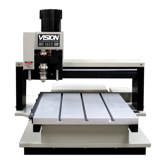
Chapter 1 Table Description This chapter briefly describes the major components of the Vision table. Figure 1.1 (see page 8) and Figure 1.3 (see page 11) show pictures of two typical engraving tables. This chapter will help you identify the parts of your Vision table discussed elsewhere in the manual.* Find the model number as referenced in the description for each type of table design. - Page 8 Chapter 1 (Figure 1.1) Moveable T-slot table format. Shown here is the top view of the Vision 1624. The Vision 1612 has a similar design. 6. Carriage Assembly 8. Y-Axis Stepper Motor (underneath) 11. Engraving Motor 7. 25 Pin Breakout Box (underneath) 5.
- Page 9 Chapter 1 3. T-Slot Table. Also referred to as the work surface, this aluminum bed supported by the linear rails allows placement of the engraving material or special clamps and fixtures. The slots in this table are shaped with an upside-down T, with the bottom of the T being a single- line slot across the top of the table (see fig 1.1b).
- Page 10 6. Engraving Motor Belt. Drive belt connecting the engraving motor to the spindle pulley. B. Tables With Moveable Gantrys (“Flatbeds”-Vision 24x24, 24x48 on page 12) The difference in design of the flatbed table versus the moving T-slot type is that the flatbed work area does not move.
- Page 11 Chapter 1 (Figure 1.3) Moveable gantry flatbed table format. Shown here is a top view of the Vision 2424. 5. Carriage Assembly 10. Engraving Motor 4. Gantry Assembly 7. Y-Axis Stepper Motor 3. X-Axis Lead Screw 2. X-Axis 9. Material Guides Linear Rails 1.
- Page 12 Chapter 1 3. X-Axis Lead Screw. This is a threaded rod located underneath the table baseplate. Combined with the stepper motor, the lead screw is rotated and causes the gantry to move along the rails in the X-axis direction (see fig 1.3b). There is also a second lead screw called in the Y-axis lead screw.
-
Page 13: Chapter 2: Setting Up The Table
Router motor (Porter cable Only) etc. Please DO NOT plug any of your Vision equipment (except the vacuum system) into this strip, as it will not function unless the Vision Series 3 controller is powered on. This is not possible with the “Auxiliary” strip, because it is always OFF unless the controller is powered on and “AUX ON/OFF”... - Page 14 Notes Page 14...
-
Page 15: Chapter 3: Engraving Head Removal Procedure
Chapter 3: Chapter 3 Engraving Head Removal Procedure Page 15... - Page 16 Chapter 3 Page 16...
-
Page 17: Chapter 4: High Frequency Router Removal
Chapter 4: Chapter 4 High Frequency Router Removal Page 17... - Page 18 Chapter 4 Page 18...
- Page 19 Chapter 4 Page 19...
- Page 20 Notes Page 20...
-
Page 21: Chapter 5: High Frequency Router Motor
Chapter 5: Chapter 5 High Frequency Router Motor Page 21... - Page 22 Notes Page 22...
- Page 23 Chapter 6: Chapter 6 Porter Cable Router Removal Procedure Page 23...
- Page 24 Chapter 6 Page 24...
-
Page 25: Chapter 7: Porter Cable Router Connections
Chapter 7: Chapter 7 Porter Cable Router Connections Page 25... - Page 26 Notes Page 26...
-
Page 27: Chapter 8: Table Adjustments
Chapter 8: Chapter 8 Table Adjustments Spindle Assembly Description (Figure 8.1) (Figure 8.2) The Series 3 Top and The Series 3 Top-Loading Bottom-Loading Collet Spindle Spindle Assembly Assembly 1. Pulley 9. Nose Cone 2. Inner Spindle Housing (under sleeve) 10. Cutter 3. - Page 28 Chapter 8 Zeroing Cutters for Top-Loaded Spindles (see page 15, figure 3.1) 1. Turn the micrometer to zero. This provides a starting point and reference for setting the depth accurately. It’s important to note that the micrometer should be threaded onto the spindle housing sufficiently to prevent excessive play in the micrometer and nosecone.
- Page 29 Chapter 8 Proximity Sensing Device All current Vision Table Models come standard with a proximity-sensing device. Below is an explanation and the procedure for operating a Vision engraving machine equipped with a proximity-sensing device. Advantage of this feature The advantage of this device is that it eliminates the need to perform a surface setting before zeroing the cutter.
- Page 30 Chapter 8 (Figure 8.4) Series 3 Spindle Shown With Diamond Drag Adapter Pulley Spindle Housing Pressure Spring Adjuster Micrometer Diamond Drag Adapter Page 30...
-
Page 31: Chapter 9: Table Maintenance
Chapter 9 Table Maintenance Vision strives for the highest quality in their manufacturing process to provide you with the most cost effective, reliable engraving machine in use today. Please remember that proper maintenance and care is necessary to achieve maximum product life expectancy. - Page 32 Chapter 9 The motor brushes on the engraving motor should be inspected regularly, and replaced when worn. Two brush assemblies are included with the accessories package. (One for each side of the motor.) Inspect the brushes for possible replacement at least every six months. (see figure 9.2) The engraving motor is the large, black motor (where applicable) on the top of the carriage assembly.
- Page 33 DO NOT attempt to lubricate the spindle or the spindle bearings. If you suspect lubrication problems, call Vision for instructions, as further lubrication may harm the machine. DO NOT lubricate the X or Y stepper motors.
- Page 34 Chapter 9 Spindle Lubrication (for Series 3 Vision Tables only) The spindle assembly in the Series 3 Vision Tables requires a monthly lubrication of the housing (as shown in Fig.9.5). Simply push the spindle up until there is a 1/3” gap between the spindle block and the “lip”...
- Page 35 When finished installing the riser blocks, be sure to retighten all bolts and threaded rods. (Figure 9.6) Riser Blocks Installation Washer Threaded Riser Blown up area Right side gantry support NOTE: With the tan colored Vision Tables, the gantry covers cannot be replaced after the risers have been installed. Page 35...
- Page 36 Using your plastic cutters to engrave metal can seriously damage them. There is a better option; Vision offers high-quality diamond drag adapters. Don’t burn out your bearings on a job that can be done just as easily as cutting plastic. The diamond drag adapter engraves virtually all-metallic surfaces, at high resolution and high speed.
-
Page 37: Chapter 10: Troubleshooting
Chapter 10: Chapter 10 Troubleshooting ENGRAVING PROBLEMS Problem: Engraving on the plate is “slanted”. Possible solutions: 1. Check material for squareness. Maybe your shear does not cut squarely. 2. Check to see if the material on the table is indeed at a true home and is square to your scale bars or stops. - Page 38 Chapter 10 Problem: You are not using a nosecone and you have uneven engraving. Possible solutions: 1. Switch to a nose-riding method. 2. Use a different method of holding the material. If you use double sided tape, it may be thick enough to change your surface flatness by a few thousandths.
- Page 39 Chapter 10 This could be in the gap between the cutter and the spindle shaft. Maybe the shaft is worn or the spindle bearings need to be replaced. Once a shaft starts to wear and a cutter is loose, the problem can worsen quickly.
- Page 40 Chapter 10 Problem: System has no movement in any one axis. Possible solutions: 1. Try to jog the problem axis using the X/Y/Z jog keys on the control unit. If OK, retry the job. 2. Check the table cable for a solid connection. 3.
Need help?
Do you have a question about the 1612 and is the answer not in the manual?
Questions and answers