Table of Contents
Advertisement
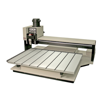
Vision 1612, 1624, 2424 and 2448
Series 5 Installation Guide
Factory Settings
Red Dot Laser Pointer Offset
X__________ Inches__
Y__________ Inches__
Braille Inserter Offset
X__________ Inches__
Y__________ Inches__
Part number 12-1087-01
© 2020 Vision Engraving & Routing Systems
mm__
mm__
mm__
mm__
This is ONLY the Installation Guide.
PLEASE review the complete User
Manual for your machine, which will be
installed on your computer after the
software installation is completed.
Revised: 5/14/2020
Advertisement
Table of Contents

Related Manuals for Vision 5 Series


Summary of Contents for Vision 5 Series
- Page 1 Vision 1612, 1624, 2424 and 2448 Series 5 Installation Guide © 2020 Vision Engraving & Routing Systems Factory Settings Red Dot Laser Pointer Offset X__________ Inches__ mm__ Y__________ Inches__ mm__ Braille Inserter Offset X__________ Inches__ mm__ Y__________ Inches__ mm__ This is ONLY the Installation Guide.
- Page 2 Vision 1612, 1624, 2424 and 2448 Series 5 Installation Guide © 2020 Vision Engraving & Routing Systems All rights reserved. No parts of this work may be reproduced in any form or by any means - graphic, electronic, or mechanical, including photocopying, recording, taping, or information storage and retrieval systems - without the written permission of the publisher.
-
Page 3: Table Of Contents
5 Spindle Options ........................... 15 NSK 50,000 RPM Spindle ................................15 UNIST Misting System ................................17 6 Network Connection ........................... 19 7 Vision Mov UI Software Installation ........................... 25 8 Vision Software Installation ........................... 33 © 2020 Vision Engraving & Routing Systems... -
Page 4: Part I Introduction
Vision 1612, 1624, 2424 and 2448 Series 5 Installation Guide Introduction This guide contains information to prepare the owner of a Vision 1612, 1624, 2424 or 2448 for the proper installation of their machine. It is the customer's responsibility to read through this guide and make sure the work area, electrical and computer requirements are met. -
Page 5: Vision Software Security Device
IMPORTANT: The Vision software is available in two versions; one with a USB dongle, and one that is "dongleless" and is loaded on to a USB Memory stick. If your machine was delivered with, or you currently have the silver, white/blue or orange software dongle, DO NOT LOSE IT! The Vision software will NOT run without the dongle plugged into the computer. -
Page 6: General Electrical And Facility Requirements
Vision 1612, 1624, 2424 and 2448 Series 5 Installation Guide General Electrical and Facility Requirements Machine Model Requirements Vision 1612, 1624, 2424 or 2448 One 110 VAC 15 Amp OR One 220 VAC 10 Amp Single Phase Optional Equipment Required in addition to the machine power above:... -
Page 7: Part Ii Machine Setup
Cutters and sample materials must be available before the scheduled installation/machine orientation date. If a chip extraction unit has not been purchased from Vision, it is highly recommended that one is available for the installation/machine orientation. If you ordered the NSK High Frequency Spindle, a clean air source is required. The air requirement is 1 CFM @ 40 psi. -
Page 8: Installation Layout Diagrams
Vision 1612, 1624, 2424 and 2448 Series 5 Installation Guide Installation Layout Diagrams 2.2.1 1612 and 1624 Engraver Layout Diagram © 2020 Vision Engraving & Routing Systems... -
Page 9: 2424 And 2448 Engraver Layout Diagram
Machine Setup 2.2.2 2424 and 2448 Engraver Layout Diagram © 2020 Vision Engraving & Routing Systems... -
Page 10: Connections
On the rear of the Vision Series 5 controller, there are 13 connection ports. Plug in all of the cables unless noted below. 1. The Aux Table plug connects to a 15 pin connector on the Vision 2424 and 2448. NOTE: This is not used with the 1612 or 1624. - Page 11 Machine Setup Vision Series 5 controller (rear view) © 2020 Vision Engraving & Routing Systems...
- Page 12 Vision 1612, 1624, 2424 and 2448 Series 5 Installation Guide Vision Series 5 pendant (rear view) NOTE: If the emergency stop screen appears on the LCD when the machine is powered on, then the emergency stop button is pressed in. This can either be the emergency stop button on the table or the emergency stop button on the pendant.
-
Page 13: Pendant Holder Installation
The 2424 and 2448 machines are shipped with a Pendant Holder to give the user a place to secure the Pendant. NOTE: Not required for 1612 or 1624. To install the Pendant Holder on the 25 Series machines, follow the below procedure. © 2020 Vision Engraving & Routing Systems... - Page 14 Vision 1612, 1624, 2424 and 2448 Series 5 Installation Guide © 2020 Vision Engraving & Routing Systems...
-
Page 15: Spindle Options
Table Cable used to connect the controller to the engraver or router's table. Be careful not to connect the Table port on the controller to the Analog Spindle Port on the NSK Power Supply Unit). © 2020 Vision Engraving & Routing Systems... - Page 16 Vision 1612, 1624, 2424 and 2448 Series 5 Installation Guide Connect the Power Cable to a standard 110 VAC power outlet and to the NSK Power Supply Unit. The cable assembly coming from the NSK Spindle has a connector to the spindle motor and an air hose. The motor connector is plugged into the Motor port and the air hose is connected to the AIR OUT port on the NSK Power Supply.
-
Page 17: Unist Misting System
(60 PSI Max) to be connected to the inlet air line. Documentation for usage of the UNIST Misting System is included with the system. Please refer to this documentation for operation details. © 2020 Vision Engraving & Routing Systems... - Page 18 Vision 1612, 1624, 2424 and 2448 Series 5 Installation Guide © 2020 Vision Engraving & Routing Systems...
-
Page 19: Network Connection
NOTE - This following section is shown on a Windows 10 PC. For Windows 7 or Windows 8, the screens are slightly different. Plug the USB end of the USB to Ethernet adapter into any open USB port on the computer. © 2020 Vision Engraving & Routing Systems... - Page 20 Vision 1612, 1624, 2424 and 2448 Series 5 Installation Guide Right click on the Windows network icon in the lower right corner of the Windows screen. Select "Open Network & Internet settings". © 2020 Vision Engraving & Routing Systems...
- Page 21 Machine Setup Select "Change adapter options". Right click on the Asix USB Ethernet connection. Select Properties. © 2020 Vision Engraving & Routing Systems...
- Page 22 Vision 1612, 1624, 2424 and 2448 Series 5 Installation Guide Select "Internet Protocol Version 4 (TCP/IPv4). Select Properties. © 2020 Vision Engraving & Routing Systems...
- Page 23 Machine Setup The screen below will appear. Enter the settings below. Select: Use the following IP address: Enter an IP address of: 192.168.100.100 Enter a Subnet mask of: 255.255.255.0 © 2020 Vision Engraving & Routing Systems...
- Page 24 Select OK. Plug one end of the network cable into the USB to Ethernet adaptor. Plug the other end of the network cable into the COMPUTER connection in the back of the Vision Series 5 controller. The network connection is now complete. Please continue to the network setup section.
-
Page 25: Vision Mov Ui Software Installation
Vision Mov UI Software Installation Power the Vision Series 5 controller on with the switch on the front. Insert the Vision USB dongle into the USB port on the computer. Navigate to the USB dongle in Windows File Explorer. Select the Start or Start.exe file to begin. - Page 26 Vision 1612, 1624, 2424 and 2448 Series 5 Installation Guide Select Step 1 Setup Machine. © 2020 Vision Engraving & Routing Systems...
- Page 27 NOTE: This screen will not appear if the Windows feature is already installed on the computer. Select Next on the "Prerequisites" installation screen. NOTE: This screen will not appear if the Windows feature is already installed on the computer. © 2020 Vision Engraving & Routing Systems...
- Page 28 Vision 1612, 1624, 2424 and 2448 Series 5 Installation Guide Select Next on the "Microsoft Vision C++ installation" screen. NOTE: This screen will not appear if the Windows feature is already installed on the computer. Select the I have read and accept the license terms box then select Install.
- Page 29 Machine Setup Select Finish on the "Setup Complete" screen. NOTE: This screen will not appear if the Windows feature is already installed on the computer. Select Next on the "Welcome screen". © 2020 Vision Engraving & Routing Systems...
- Page 30 Vision 1612, 1624, 2424 and 2448 Series 5 Installation Guide Select Next on the "Choose a file location" screen. Select Install on the "Begin installation" screen. © 2020 Vision Engraving & Routing Systems...
- Page 31 Machine Setup Select Close on the "Successful Install" screen. The VisMovUI screen will appear. Select the Machine in the "Machines Discovered on Network" screen and click Select. © 2020 Vision Engraving & Routing Systems...
- Page 32 Vision 1612, 1624, 2424 and 2448 Series 5 Installation Guide The VisMovUI program will appear. Select the Minimize button. The Vision Move UI program is now installed. Please continue to the network setup section. © 2020 Vision Engraving & Routing Systems...
-
Page 33: Vision Software Installation
Machine Setup Vision Software Installation Insert the Vision USB dongle into the USB port on the computer. Navigate to the USB dongle in Windows File Explorer. Select the Start or Start.exe file to begin. Select 1612 and larger. © 2020 Vision Engraving & Routing Systems... - Page 34 Vision 1612, 1624, 2424 and 2448 Series 5 Installation Guide Select Step 2 Install Vision Software. Select Next on the "Welcome" screen. © 2020 Vision Engraving & Routing Systems...
- Page 35 Machine Setup Select Install on the "Ready to Install" screen. Select Finish on the "Complete Install" screen. © 2020 Vision Engraving & Routing Systems...
- Page 36 Vision 1612, 1624, 2424 and 2448 Series 5 Installation Guide Select the language desired and select OK on the "Vision Pro install" screen. Make sure the USB dongle is installed and select Next on the "USB Flash Dongle" screen. © 2020 Vision Engraving & Routing Systems...
- Page 37 Machine Setup Select Next on the "Vision 10 setup" screen. NOTE: The installation will display "Vision Pro 10 Setup", "Vision Expert 10 Setup" or "Vision Express 10 Setup" depending on which version has been purchased. Select the I accept the terms of the license agreement box then select Next on the "License Agreement"...
- Page 38 Vision 1612, 1624, 2424 and 2448 Series 5 Installation Guide Select Next from the "Choose Destination Location" screen. NOTE: The installation folder will be either "C:\Vision Pro 10", "C:\Vision Expert 10" or "C:\Vision Express 10" depending on which version has been purchased.
- Page 39 Machine Setup The installation will continue. Select Vision S5 - Engravers and select Next. © 2020 Vision Engraving & Routing Systems...
- Page 40 Vision 1612, 1624, 2424 and 2448 Series 5 Installation Guide Select the driver for the that matches the machine purchased and select Next. NOTE: If ADA drivers or a center origin driver is needed, select them also. Select Continue on the "Font Installation" screen.
- Page 41 Machine Setup The installation will search for Vision fonts. Select the disk drive to search for additional fonts that may be on the computer and select Yes. NOTE: Typically drive C:\ is selected. © 2020 Vision Engraving & Routing Systems...
- Page 42 Vision 1612, 1624, 2424 and 2448 Series 5 Installation Guide The installation will search for additional fonts. NOTE: This may take a few minutes. Select OK on the "Font Installation Complete" screen. © 2020 Vision Engraving & Routing Systems...
- Page 43 NOTE: The install may or may not ask to restart the computer. Select Exit from the initial screen. The Vision 10 software and Vision Manuals icon will now be on the Windows desktop. © 2020 Vision Engraving & Routing Systems...
- Page 44 Vision 1612, 1624, 2424 and 2448 Series 5 Installation Guide © 2020 Vision Engraving & Routing Systems...
Need help?
Do you have a question about the 5 Series and is the answer not in the manual?
Questions and answers