Sign In
Upload
Download
Table of Contents
Contents
Add to my manuals
Delete from my manuals
Share
URL of this page:
HTML Link:
Bookmark this page
Add
Manual will be automatically added to "My Manuals"
Print this page
×
Bookmark added
×
Added to my manuals
Manuals
Brands
Vision Manuals
Engraver
16 Series
User manual
Vision 16 Series User Manual
Hide thumbs
1
2
Table Of Contents
3
4
5
6
7
8
9
10
11
12
13
14
15
16
17
18
19
20
21
22
23
24
25
26
27
28
29
30
31
page
of
31
Go
/
31
Contents
Table of Contents
Bookmarks
Table of Contents
Table of Contents
Part I Introduction
Disclaimer and Warranty Information
Safety
Part II Locating the Engraver
Part III Installation Layout Diagrams
Part IV Table Descriptions
Part V Table Connections
Part VI Zeroing the Cutter
Part VII Proximity Sensor
Part VIII Maintenance
Part IX Riser Block Extensions
Part X Collets and Diamond Drag Adapter
Part XI Troubleshooting
Advertisement
Quick Links
Download this manual
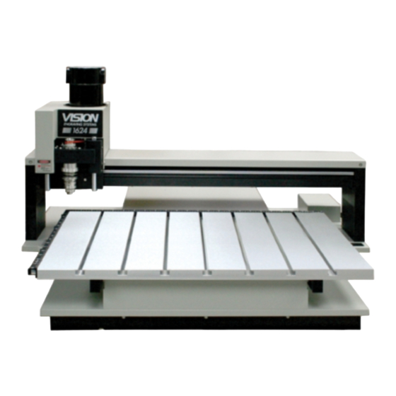
Vision 16 Series and 24 Series
Engraver User Manual
© 2013 Vision Engraving & Routing Systems
Revised: 6/11/2013
Table of
Contents
Previous
Page
Next
Page
1
2
3
4
5
Advertisement
Table of Contents
Need help?
Do you have a question about the 16 Series and is the answer not in the manual?
Ask a question
Questions and answers
Related Manuals for Vision 16 Series
Engraver Vision 1612 User Manual
Engraving systems (41 pages)
Engraver Vision 5 Series Installation Manual
(45 pages)
Engraver Vision 5 Series User Manual
(98 pages)
Engraver Vision PHOENIX TABLE Operating Manual
Phoenix engraving table (36 pages)
Engraver Vision Phoenix 1212 Installation Manual
(39 pages)
Engraver Vision Phoenix 1212 S5 Installation Manual
(35 pages)
Engraver Vision 1624R Installation Manual
(69 pages)
Engraver Vision Max Pro User Manual
Computerized engraving system (183 pages)
Engraver Vision VE-810 Operation Manual
(69 pages)
Engraver Vision VE810 S5 Installation Manual
(34 pages)
Engraver Vision MaxPro Operation Manual
(203 pages)
Engraver Vision VE810 4 Series User Manual
(145 pages)
Engraver Vision Express S5 Installation Manual
(33 pages)
Engraver Vision Express S5 User Manual
(155 pages)
Engraver Vision SP Series User Manual
(7 pages)
This manual is also suitable for:
24 series
Table of Contents
Print
Rename the bookmark
Delete bookmark?
Delete from my manuals?
Login
Sign In
OR
Sign in with Facebook
Sign in with Google
Upload manual
Upload from disk
Upload from URL


Need help?
Do you have a question about the 16 Series and is the answer not in the manual?
Questions and answers