
Related Manuals for Emerson Liebert GXT 10KVA


Summary of Contents for Emerson Liebert GXT 10KVA
- Page 1 OWER VAILABILITY ™ AINTENANCE YPASS ABINET FOR FINITY & GXT 10 ANUAL...
-
Page 3: Table Of Contents
MPORTANT AFETY NSTRUCTIONS ............2 LOSSARY YMBOLS ENERAL... - Page 4 ............23 AINTENANCE Proper Care.
-
Page 5: Save These Instructions
MPORTANT AFETY NSTRUCTIONS SAVE THESE INSTRUCTIONS This manual contains important instructions that should be closely followed during installation and maintenance of this Maintenance Bypass Cabinet. This product is designed for commercial/industrial use only. This product is not intended for use with life support and other designated “critical”... -
Page 6: Glossary O F Symbols
LOSSARY YMBOLS Risk of Electrical Shock Indicates Warning or Caution Followed by Important Instructions AC Input AC Output Requests the user to consult the manual Equipment Grounding Conductor... -
Page 7: General Description
ENERAL ESCRIPTION Congratulations on your purchase of Liebert’s Nfinity™ Maintenance Bypass Cabinet with Config- urable Output Distribution. As with every Liebert product, we stand behind our quality. If you have any questions concerning this Maintenance Bypass Cabinet, please feel free to contact your local dealer, Liebert representative, or call the appropriate Technical Support number listed on the back of this manual. -
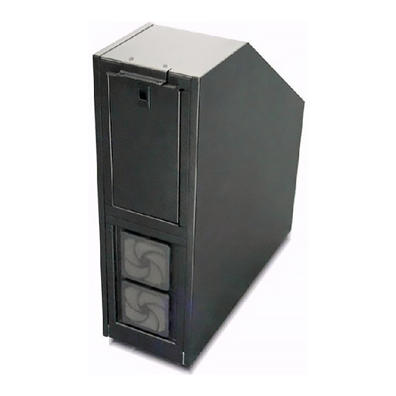
Page 8: Front View
Figure 1 Front view Bypass availability indicator (amber) Bypass switch (SW1) UPS input power present (amber) Output breaker (CB1) UPS output availability indicator (green) UPS input switch (SW2) Cooling fans (transformer models only) Support bracket General Description... -
Page 9: Figure 2 Rear View (Without Transformer)
Figure 2 Rear view (without transformer) Configurable output distribution (optional) Hardwire output (standard) UPS input (TB3) Maintenance bypass input (TB1) Hardwire output terminal block (TB5) UPS output (TB4) Maintenance bypass input (TB2) Support bracket General Description... -
Page 10: Figure 3 Rear View (With Transformer)
Figure 3 Rear view (with transformer) Configurable output distribution (optional) Hardwire output (standard) Tap selector (TB4) Maintenance bypass input (TB1) (TB2) Hardwire output terminal block (TB6) UPS output (TB5) UPS input (TB3) Support bracket General Description... -
Page 11: Modes Of Operation
ODES OF PERATION The Nfinity Maintenance Bypass Cabinet is designed to operate in two modes: UPS Mode and Bypass Mode. UPS Mode While the Nfinity Maintenance Bypass Cabinet is in UPS Mode, the UPS is supplying the connected load with continuous, high quality AC power. In this mode of operation, the load is protected by the UPS. -
Page 12: Major Components
AJOR OMPONENTS The following is a general description of each component and its functions. Please review this section carefully, as it will give you a better understanding as to how the Nfinity Maintenance Bypass Cabi- net operates. Bypass Switch The Bypass Switch allows easy and rapid transfer of connected loads between the UPS and Bypass source. -
Page 13: Figure 5 Clearances
REPARATION These installation instructions provide all the information needed for positioning the Nfinity Mainte- nance Bypass Cabinet (including environmental requirements) and for connecting the input and out- put power cables. Inspection Upon receiving the Nfinity Maintenance Bypass Cabinet, examine the packaging for any signs of mis- handling or damage. -
Page 14: Unloading
NLOADING The unit frame is bolted to the shipping pallet to ensure safety. Liebert recommends using a pallet jack to transport the unit to its operating location prior to unbolting the unit. Unloading the Maintenance Bypass Cabinet CAUTION This Maintenance Bypass Cabinet is heavy (see weight in Table 2). At least two people should assist to unload it from the pallet. -
Page 15: Stationary Mounting
Stationary Mounting Additional stability can be added by bolting the mounting brackets (used in shipping) to the floor. Mounting bracket on rear of unit For greater stability, use a higher-grade bolt. Refer to the dimensions below when drilling holes for stationary mounting. -
Page 16: Cable Installation
ABLE NSTALLATION Wiring Preparation WARNING Please read this section thoroughly before attempting to install wiring to this unit. Be sure that the unit is not connected to any AC mains power source or UPS before installing any wir- ing to this unit. This Maintenance Bypass Cabinet should be installed by a qualified / certified electri- cian. -
Page 17: Figure 7 Maintenance Bypass Cabinet With Transformer
Figure 7 Maintenance Bypass Cabinet with transformer Input 2 Single input jumper (remove for dual input feeds) UPS Input Input 1 Switch UPS Input Figure 8 Maintenance Bypass Cabinet without transformer Input 2 Single input jumper (remove for dual input feeds) UPS Input Input 1 Switch... -
Page 18: Removing The Cover Plates
Removing the Cover Plates On the back of the Maintenance Bypass Cabinet, cover plates are over the input and output terminals (see illus- tration at right). Remove these using a phillips screw- driver. Keep screws and plates to one side. Power Cable Installation Refer to Table 3 below when selecting cables. -
Page 19: Input And Output Wiring
Input and Output Wiring NOTE Input wiring must be installed using conduit. 208 input voltage jumper—if only the connections for 208 VAC are made between the UPS and theNfinity Maintenance Bypass, the 208 input voltage jumper must be installed for proper operation. -
Page 20: Figure 9 Electrical Connections-Transformer Model Mbc
Figure 9 Electrical connections—transformer model MBC Common Ground Wire Connection Torque Value: 13 in-lbs Common Ground Wire Connection Torque Value: 120 in-lbs TB4 Tap Selector Terminal Block Wire Connection Torque Value: 28 in-lbs TB1 & TB2 Maintenance Bypass Terminal Blocks Wire Connection Torque Value: 50 in-lbs GEC (Grounding Electrode Conductor) -
Page 21: Figure 10 Electrical Connections-Non-Transformer Model Mbc
Figure 10 Electrical connections—non-transformer model MBC Common Ground Wire Connection Torque Value: 13 in-lbs Common Ground Wire Connection Torque Value: 120 in-lbs TB3 UPS Input Terminal Block Wire Connection Torque Value: 28 in-lbs TB1 Maintenance Bypass Terminal Block Wire Connection Torque Value: 50 in-lbs Common Ground Wire Connection... -
Page 22: Figure 11 Connecting Nfinity To Maintenance Bypass With Transformer
Figure 11 Connecting Nfinity to Maintenance Bypass with transformer Input 2 Input 1 Flexible conduit Ensure that both tap selectors are set to the correct input voltage NOTE 1. SINGLE-SOURCE FEED—If feeding the Maintenance Bypass Cabinet from a single source, the input connection may be made to either TB1 or TB2. 2. -
Page 23: Figure 12 Connecting Nfinity To Maintenance Bypass Without Transformer
Figure 12 Connecting Nfinity to Maintenance Bypass without transformer Input 2 Input 1 Flexible conduit Ensure that the tap selector is set to the correct input voltage NOTE 1. SINGLE-SOURCE FEED—If feeding the Maintenance Bypass Cabinet from a single source, the input connection may be made to either TB1 or TB2. 2. -
Page 24: Figure 13 Connecting Maintenance Bypass To Gxt10000T-208X
Figure 13 Connecting Maintenance Bypass to GXT10000T-208X FINITY Input 2 Input 1 Flexible conduit Input GXT10000T-208X CAUTION It is mandatory to connect exactly as shown. NOTE 1. SINGLE-SOURCE FEED—If feeding the Maintenance Bypass Cabinet from a single source, the input connection may be made to either TB1 or TB2. 2. -
Page 25: Figure 14 Connecting Maintenance Bypass To Gxt10000T-240X
Figure 14 Connecting Maintenance Bypass to GXT10000T-240X FINITY Input 2 Input 1 Flexible conduit Input GXT10000T-240X NOTE 1. SINGLE-SOURCE FEED—If feeding the Maintenance Bypass Cabinet from a single source, the input connection may be made to either TB1 or TB2. 2. -
Page 26: Operation
PERATION Start-Up and Initialization To start up the Nfinity UPS while it is connected to the Nfinity Maintenance Bypass: 1. Set the Maintenance Bypass switch (SW1) to the UPS position on the Maintenance Bypass Cabinet. 2. Close the UPS source switch (SW2). 3. -
Page 27: Maintenance
AINTENANCE Proper Care Keeping your Liebert Nfinity Maintenance Bypass Cabinet operating properly is imperative to opti- mal performance and life of the unit. It is recommended that a certified technician perform preventive and corrective maintenance. Liebert Global Services (LGS) is dedicated to ensuring the highest level of performance and unmatched support for your Nfinity Maintenance Bypass Cabinet. -
Page 28: Specifications
PECIFICATIONS General & Environmental Unit Rating Safety Standards Mechanical Width Depth Dimensions Height Weight Environmental Operating Temperature (max) Relative Humidity Maximum Operating Altitude Input Data Nominal Input Voltage Input Frequency (nominal) Input Frequency Range Output Data Output Voltage Transfer Time Output Frequency * Transformerless model requires neutral input Rating... - Page 29 Specifications NOTES...
- Page 30 Specifications...
-
Page 32: Power Availability
AINTENANCE YPASS & GXT 10 The Company Behind the Products With over a million installations around the globe, Liebert is the world leader in computer protection systems. Since its founding in 1965, Liebert has developed a complete range of support and protection systems for sensitive electronics: •...
Need help?
Do you have a question about the Liebert GXT 10KVA and is the answer not in the manual?
Questions and answers