Table of Contents
Troubleshooting

Subscribe to Our Youtube Channel
Related Manuals for Emerson Branson DCX F-DP


Summary of Contents for Emerson Branson DCX F-DP
- Page 1 Original Instructions 4000872EN - REV. 01 DCX F-DP Rack Mount Power Supply I n s t r u c t i o n M a n u a l Branson Ultrasonics Corp. 120 Park Ridge Road Brookfield, CT 06804 (203) 796-0400 http://www.bransonultrasonics.com...
-
Page 2: Manual Change Information
Manual Change Information At Branson, we strive to maintain our position as the leader in ultrasonics plastics joining, metal welding, cleaning and related technologies by continually improving our circuits and components in our equipment. These improvements are incorporated as soon as they are developed and thoroughly tested. - Page 3 Foreword Congratulations on your choice of a Branson Ultrasonics Corporation system! The Branson DCX F-DP Rack Mount Power Supply system is process equipment for the joining of plastic parts using ultrasonic energy. It is the newest generation of product using this sophisticated technology for a variety of customer applications. This Instruction Manual is part of the documentation set for this system, and should be kept with the equipment.
- Page 4 4000872EN REV. 01...
-
Page 5: Table Of Contents
Table of Contents Chapter 1: Safety and Support Safety Requirements and Warnings........2 General Precautions . - Page 6 Ultrasonics Test Procedure ..........136 Using the I/O Connections .
- Page 7 List of Figures Chapter 1: Safety and Support Figure 1.1 Safety-related Labels found on the DCX F-DP Rack Mount Power Supply..4 Figure 1.2 Safety-related Labels found on the DCX F-DP Rack Mount Power Supply..5 Chapter 2: Introduction Figure 2.1 The DCX F-DP Rack Mount Power Supply .
- Page 8 Chapter 8: PROFIBUS DP Operation Figure 8.1 LED Status Indicator ..........140 Figure 8.2 Writing and reading Parameters .
- Page 9 List of Tables Chapter 1: Safety and Support Table 1.1 Authorized Service Center (North America) ......9 Table 1.2 Authorized Service Centers (South America) .
- Page 10 Table 5.20 Tip to horn torque values ......... . 80 Table 5.21 Continuous Duty Max.
- Page 11 Table 8.6 Communication Channel (PKW) ........145 Table 8.7 Subdivisions of the communication channel (PKW) .
- Page 12 Table B.2 Seek Stack Parameters ......... . 204 Table B.3 Test Stack Parameters.
-
Page 13: Chapter 1: Safety And Support
Chapter 1: Safety and Support 1.1 Safety Requirements and Warnings ....... 2 1.2 General Precautions . -
Page 14: Safety Requirements And Warnings
Safety Requirements and Warnings This chapter contains an explanation of the different Safety Notice symbols and icons found both in this manual and on the product itself and provides additional safety information for ultrasonic welding. This chapter also describes how to contact Branson for assistance. - Page 15 CAUTION Loud Noise Hazard Loud noise hazard. Ear protection must be worn. CAUTION Heavy Object Heavy object. To avoid muscle strain or back injury, use lifting aids and proper lifting techniques. NOTICE If this situation is not avoided, the system or something in its vicinity might get damaged.
-
Page 16: Symbols Found On The Product
1.1.2 Symbols Found on the Product The DCX F-DP Rack Mount Power Supply has several safety-related labels on it to indicate the presence of hazardous voltages inside the unit. Figure 1.1 Safety-related Labels found on the DCX F-DP Rack Mount Power Supply WARNING To prevent electrical shock wait 5 minutes after disconnecting... -
Page 17: Figure 1.2 Safety-Related Labels Found On The Dcx F-Dp Rack Mount Power Supply
Figure 1.2 Safety-related Labels found on the DCX F-DP Rack Mount Power Supply WARNING MADE IN MEXICO GROUND UNI T BEFORE OPER ATING 4000872EN REV. 01... -
Page 18: General Precautions
General Precautions Take the following precautions before servicing the power supply: • Be sure the power is disconnected before making any electrical connections • To prevent the possibility of an electrical shock, always plug the power supply into a grounded power source •... -
Page 19: Intended Use Of The System
WARNING Corrosive Material Hazard First aid measures (in case of electrolyte leakage from the battery): Eye Contact: Flush the eyes with plenty of clean water for at least 15 minutes immediately, without rubbing. Get immediate medical treatment. If appropriate procedures are not taken, this may cause eye injury. Skin Contact: Wash the affected area under tepid running water using a mild soap. -
Page 20: Regulatory Compliance
1.2.4 Regulatory Compliance This product meets electrical safety requirements and EMC (Electromagnetic Compliance) requirements for North America, Great Britain, and the European Union. 4000872EN REV. 01... -
Page 21: How To Contact Branson
How to Contact Branson Branson is here to help you. We appreciate your business and are interested in helping you successfully use our products. To contact Branson for help, use the following telephone numbers, or contact the office nearest you. 1.3.1 Authorized Service Center (North America) Table 1.1... -
Page 22: Table 1.3 Authorized Service Centers (Asia)
Hong Kong Office info@emerson.com Kowloon, Hong Kong Branson Ultrasonics 8/35, Marol Co-Op Industrial Estate Tel: 91-22-2850-5570 Div. of Emerson Electric Co. P. Ltd. “Ajanta House” M.V. Road, Andheri (East) Fax: 91-22-2850-8681 India Mumbai 400 059, India Branson Ultrasonics 4-3-14 Okada, Atsugi-Shi... - Page 23 Name Address Tel/Fax Number No. 20, Jalan Rajawali 3, Branson Ultrasonics Puchong Jaya Industrial Park Tel: 603-8076-8608 Div. of Emerson Elec (M) Sdn Bhd. Batu 8, Jalang Puchong Fax: 603-8076-8302 Malaysia 47170 Puchong, Selangor Malaysia Emerson Building 104 Laguna Blvd.
-
Page 24: Table 1.4 Authorized Service Centers (Europe)
Fax: 420-374-625-617 1 Rue des Pyrenees Silic 404 Branson Ultrasons Tel: 33-1-4180-2550 94573 Rungis Cedex France Fax: 33-1-4687-8729 France Niederlassung der EMERSON Tel: 49 (0)6074/497-0 Technologies GmbH & Co. Branson Ultraschall Tel: 49 (0)6074/497-784 European Headquarters Waldstraße 53-55 Fax: 49 (0)6074/497-199... - Page 25 Table 1.4 Authorized Service Centers (Europe) Name Address Tel/Fax Number Sonifers: Case Postale 1031 Tel: 41-22-304-8340 Bransonics: Chemin du Branson Ultrasonics S.A. Faubourg-de-Cruseilles 9 Tel: 41-58-611-1222 Switzerland CH 1227, Carouge, Fax: 41-22-304-8359 Switzerland 158 Edinburgh Avenue Branson Ultrasonics Tel: 44-1753-756675 Slough, Berkshire United Kingdom Fax: 44-1753-551270...
- Page 26 4000872EN REV. 01...
-
Page 27: Chapter 2: Introduction
Chapter 2: Introduction 2.1 Models Covered ..........16 2.2 Compatibility with other Branson Products . -
Page 28: Models Covered
Models Covered This manual covers all models of the DCX F-DP Rack Mount Power Supply. Table 2.1 Models Covered in this Manual Frequency Power 1250 W 101-132-2067 20 kHz 2500 W 101-132-2068 4000 W 101-132-2069 30 kHz 1500 W 101-132-2066 40 kHz 800 W 101-132-2065... -
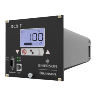
Page 29: Figure 2.1 The Dcx F-Dp Rack Mount Power Supply
2.1.1 Overview of these Models Figure 2.1 The DCX F-DP Rack Mount Power Supply The DCX F-DP Rack Mount Power Supply generates ultrasonic energy through an ultrasonic converter for welding plastics. Several models are available, depending on the desired frequency (for example, 20 kHz) and the desired power range (for example, 4.0 kW). -
Page 30: Compatibility With Other Branson Products
Compatibility with other Branson Products Table 2.2 Power Supply Compatibility with Branson Converters DCX F-DP Rack Converter Mount Models CR-20S CR-20C CH-20S (932 AH SPL) 20 kHz CH-20C CS-20S CS-20C CR-30S CR-30C CH-30S 30 kHz CH-30C CS-30S CS-30C CR-40S (4TH) 40 kHz CR-40C 4000872EN REV. -
Page 31: Features
50/60 Hz line current to 20 kHz, 30 kHz or 40 kHz electrical energy. The system controller controls the welding system. Listed below are the control features of the Branson DCX F-DP Rack Mount Power Supply ultrasonic welding system: Table 2.3... - Page 32 Table 2.3 Control Features Name Description Ensures operation at resonance; minimizes tuning errors; and Seek operates the stack at low amplitude (10%), then provides a means of sensing and storing the resonant operating frequency value. Start-up At start-up, the controls test the major internal components. Diagnostics Protects the power supply by providing six levels of protection: System Protection...
- Page 33 2.3.3 The Actuator The DCX F-DP Rack Mount Power Supply can interface with actuator signals, only when operating in manual mode. 2.3.4 Converter/Booster/Horn Assembly The Converter The ultrasonic electrical energy from the power supply is applied to the converter (sometimes called the transducer). This transforms the high frequency electrical oscillations into mechanical vibrations at the same frequency as the electrical oscillations.
-
Page 34: Controls And Indicators
Controls and Indicators 2.4.1 DCX F-DP Rack Mount Power Supply Front Panel Figure 2.2 DCX F-DP Rack Mount Power Supply Front Panel Controls and Indicators Table 2.4 DCX F-DP Rack Mount Power Supply Front Panel Controls and Indicators Reference Description For detailed information refer to Figure 2.3 LCD Description Table 2.5 LCD... - Page 35 Table 2.4 DCX F-DP Rack Mount Power Supply Front Panel Controls and Indicators Reference Description Configuration Key Use the Configuration key to change system registers. For information on using the Configuration key to set system registers 7.5 Configuring the Power Supply Registers.
-
Page 36: Figure 2.3 Lcd Description
Figure 2.3 LCD Description 90 100 Table 2.5 LCD Description Reference Description Numeric Display Displays the Power Supply amplitude settings, weld time settings, weld energy settings, peak power settings, scrub time settings, register numbers, register values or alarm numbers. Continuous Mode Icon Indicates the power supply is running in Continuous mode. - Page 37 Table 2.5 LCD Description Reference Description Peak Power Icon Indicates the power supply is running in Peak Power mode. When in Peak Power mode, the peak power percentage is shown on the numeric display in conjunction with the % icon. The peak power setting may range from 1% to 100% of the maximum power supply output power.
- Page 38 Table 2.5 LCD Description Reference Description Circle Icon Indicates that the value shown on the numeric display is a register value. Use up and down keys to modify the register value. For more information see 7.5 Configuring the Power Supply Registers.
-
Page 39: Figure 2.4 Dcx F-Dp Rack Mount Power Supply Back Panel
2.4.2 DCX F-DP Rack Mount Power Supply Connections Figure 2.4 DCX F-DP Rack Mount Power Supply Back Panel Table 2.6 Connections to the DCX F-DP Rack Mount Power Supply Item Name Function Detachable connector block for connecting the input Line Input Connector power. -
Page 40: Welding Systems
Welding Systems 2.5.1 Principle of Operation Thermoplastic parts are welded ultrasonically by applying high frequency vibrations to the parts being assembled. The vibrations, through surface and intermolecular friction, produce a sharp rise in temperature at the welding interface. When the temperature is high enough to melt the plastic, there is a flow of material between the parts. -
Page 41: Glossary
Glossary The following terminology may be encountered when using or operating a DCX F-DP Rack Mount Power Supply ultrasonic welding system: Table 2.7 Glossary Name Description The unit which houses the converter/booster/horn stack assembly in a rigid mounting, allowing the stack to move up and down, Actuator either mechanically or pneumatically, applying force to the part at a user-adjustable force and velocity. - Page 42 Table 2.7 Glossary Name Description An offset factor applied to the ultrasonic frequency stored in the Frequency Offset power supply. A black surface condition, that results from friction between metal Fretting Corrosion parts, that appears on the converter-booster-horn stack mating surfaces.
- Page 43 Table 2.7 Glossary Name Description The use of ultrasonic vibrations to generate heat and subsequently melt the mating surfaces of two thermoplastic parts. When Ultrasonic Welding ultrasonic vibrations stop, the molten material resolidifies, and a weld occurs. A unique 12 character long alphanumeric ID used to keep track of User ID user access to the web page interface.
- Page 44 4000872EN REV. 01...
-
Page 45: Chapter 3: Delivery And Handling
Chapter 3: Delivery and Handling 3.1 Shipping and Handling ........34 3.2 Receiving. -
Page 46: Shipping And Handling
Shipping and Handling CAUTION Heavy Object The power supply may be heavy. Handling, unpacking, and installation may require the assistance of a colleague or the use of lifting platforms or hoists. 3.1.1 Environmental Specifications The DCX F-DP Rack Mount Power Supply is an electronic unit that converts line voltage to ultrasonic energy and responds to user input for regulating the weld process. -
Page 47: Receiving
Receiving The DCX F-DP Rack Mount Power Supply is a sensitive electronic device. Many of its components can be harmed if the unit is dropped or otherwise mishandled. Scope of Delivery Branson equipment is carefully checked and packed before dispatch. It is recommended, however, that you follow the procedure below upon receiving your DCX F-DP Rack Mount Power Supply. -
Page 48: Unpacking The Power Supply
Unpacking the Power Supply NOTICE If there are any visible signs of damage to the shipping containers or the product, or you later discover hidden damage, NOTIFY YOUR CARRIER IMMEDIATELY. Save the packing material. The power supply is fully assembled. It is shipped in a sturdy cardboard box. Some additional items are shipped in the box with the power supply. -
Page 49: Take Inventory Of Small Parts
Take Inventory of Small Parts Table 3.4 Small Parts included with the Power Supply Assemblies Part or Kit 20 kHz 30 kHz 40 kHz Mylar®* plastic film Washer Kit Silicone Grease Spanners (2) * Mylar is a registered trademark of DuPont Teijin Films. 3.4.1 Cables The RF cable connects the power supply to the converter. -
Page 50: Returning Equipment
Returning Equipment If you are returning equipment to Branson Ultrasonic Corporation, please call your Customer Service Representative to receive approval to return the goods. Refer to How to Contact Branson. 4000872EN REV. 01... -
Page 51: Chapter 4: Technical Specifications
Chapter 4: Technical Specifications 4.1 Technical Specifications ........40 4.2 Physical Description . -
Page 52: Technical Specifications
Technical Specifications NOTICE All specifications are subject to change without notice. 4.1.1 Environmental Specifications The DCX F-DP Rack Mount Power Supply has the following environmental specifications: Table 4.1 Environmental Specifications Environmental Condition Acceptable Range Ambient Operating Temperature +41°F to +104°F (+5°C to +40°C) Storage / Shipping Temperature -13°F to +131°F (-25°C to +55°C) Operating Altitude... -
Page 53: Table 4.3 Input Current And Fuse Specifications
Input Current and Fuse Specifications Table 4.3 Input Current and Fuse Specifications Model Power Current Rating 1250 W 7 A Max. @ 200 - 240 V / 15 A Fuse 20 kHz 2500 W 14 A Max. @ 200 - 240 V / 15 A Fuse 4000 W 25 A Max. -
Page 54: Physical Description
Physical Description This section describes the physical dimensions of the DCX F-DP Rack Mount Power Supply. NOTICE Dimensions are nominal. Table 4.5 Dimensions and Weights of DCX F-DP Rack Mount Power Supply Size Width Height Depth Weight 4.2” 8 lb Small 106 mm 3.6 kg... -
Page 55: Eu Declaration Of Conformity
EU Declaration of Conformity Figure 4.1 EU Declaration of Conformity 4000872EN REV. 01... -
Page 56: Declaration Of Conformity
UK Declaration of Conformity Figure 4.2 UK Declaration of Conformity 4000872EN REV. 01... -
Page 57: Profibus Certificate
PROFIBUS Certificate Figure 4.3 PROFIBUS Certificate 4000872EN REV. 01... -
Page 58: Figure 4.4 Association Trademark
4.5.1 Terms of use for Trademarks of PROFIBUS & PROFINET International PI Figure 4.4 Association Trademark Figure 4.5 Technology Trademarks PROFI ener gy PRO FI s af e Figure 4.6 Certification Trademark Figure 4.7 Certified by PI Trademark The Association Trademark, the Technology Trademarks, the Certification Trademark and the Certified by PI Trademark are protected trademarks. -
Page 59: General Terms
General Terms The Association Trademark, the Technology Trademarks, the Certification Trademark and the Certified by PI Trademark may only be used in the registered form in the course of business by holders of the right of use. The Association Trademark, Technology Trademarks, Certification Trademark or the Certified by PI Trademark may not be modified with respect to the registered form or combined with other characteristics than the additions approved by PI. - Page 60 The right to use the Certified by PI Trademark terminates automatically in the event that the applicant has given negative statements to the public about PI and/or its technologies without prior consultation or clarification with PI, and when the accreditation as PICC, PITC or PITL has ended.
-
Page 61: Chapter 5: Installation And Setup
Chapter 5: Installation and Setup 5.1 About Installation ..........50 5.2 Installation Requirements . -
Page 62: About Installation
About Installation This chapter is intended to help the installer with the basic installation and setup of your new DCX F-DP Rack Mount Power Supply. CAUTION Heavy Object The power supply, and related components are heavy. Handling, unpacking, and installation may require the assistance of a colleague or the use of lifting platforms or hoists. -
Page 63: Installation Requirements
Installation Requirements This section covers the location requirements, mounting options, power supply dimensions, environmental requirements, and electrical requirements, to help you plan and execute your installation successfully. 5.2.1 Installing the DCX F-DP Rack Mount Power Supply Drawers in a Customer Rack The power supply units can be installed in any rack complying with the 19”... - Page 64 Figure 5.1 DCX F-DP Rack Mount Power Supply Dimensional Drawing (Small) 4000872EN REV. 01...
-
Page 65: Figure 5.2 Dcx F-Dp Rack Mount Power Supply Dimensional Drawing (Medium)
Figure 5.2 DCX F-DP Rack Mount Power Supply Dimensional Drawing (Medium) 4000872EN REV. 01... -
Page 66: Figure 5.3 Dcx F-Dp Rack Mount Power Supply Dimensional Drawing (Large)
Figure 5.3 DCX F-DP Rack Mount Power Supply Dimensional Drawing (Large) 4000872EN REV. 01... -
Page 67: Table 5.1 Environmental Requirements
5.2.4 Environmental Requirements Verify the DCX F-DP Rack Mount Power Supply is operated in an environment that meets the temperature and humidity requirements indicated in Table 5.1 Environmental Requirements. Table 5.1 Environmental Requirements Environmental Condition Acceptable Range Ambient Operating Temperature +41°F to +104°F (+5°C to +40°C) Storage / Shipping Temperature -13°F to +131°F (-25°C to +55°C) -
Page 68: Installation Steps
Installation Steps WARNING High Voltage Hazard To prevent the possibility of an electrical shock: • Ensure the power source is disconnected before beginning work on line connections • Always plug the power supply into a grounded power source • To prevent the possibility of an electrical shock, ground the power supply by securing an 8 gauge grounded conductor to the ground screw located next to the air outlet •... -
Page 69: Mount The Power Supply
5.3.1 Mount the Power Supply The cable lengths are limited based on the operating frequency of the welding system. Performance and results can suffer if the RF cable is crushed, pinched, damaged or modified. Contact your Branson Representative if you have special cable requirements. Do not place the power supply on the floor or in other locations that will allow dust, dirt or contaminants to be drawn into the power supply. -
Page 70: Electrical Connections
5.3.3 Electrical Connections Figure 5.5 DCX F-DP Rack Mount Power Supply Connections Table 5.3 DCX F-DP Rack Mount Power Supply Connections Item Name Line Input Connector User I/O Connector Ethernet Port RF Connector 4000872EN REV. 01... -
Page 71: User I/O
User I/O 5.4.1 User I/O Connections NOTICE User I/O interface is only available in manual mode. The user I/O is a standard interface for automation, provided on the power supply. It provides the ability to make your own interface for your automation, actuator interface, special control, or reporting needs. -
Page 72: Figure 5.6 User I/O Cable Identification And Wire Color Diagram
Figure 5.6 User I/O Cable Identification and Wire Color Diagram User I/O Cable Stripped Jacket one end, HD-26 male connector other end (cable length as ordered) Wire Color Diagram Two Colors = Insulator/Stripe Three Colors = Insulator/Stripe/Dot Table 5.4 User I/O Cable Identification and Wire Color Diagram Item Description Part number... -
Page 73: Table 5.5 User I/O Cable Pin Assignments
5.4.2 User I/O Cable Pin Assignments Table 5.5 User I/O Cable Pin Assignments Available Signal Input/Output Signal Range Color Function Type Digital in 1 Table Digital in 2 5.7 Digital Digital 0V to 24V ±10%, Input Input 12mA Digital in 3 Functions Digital in 4 24V ±10%, 250mA... - Page 74 Table 5.5 User I/O Cable Pin Assignments Available Signal Input/Output Signal Range Color Function Type Analog out 1 Table Red/Blk/Wht 5.10 Analog 0V to 10V ±5%, Analog Output 1mA Max Analog out 2 Grn/Blk/Wht Output Functions Analog Analog Ground Orn/Blk/Wht Ground 4000872EN REV.
-
Page 75: Table 5.6 Default Branson User I/O Connector Pin Assignments
5.4.3 Default Branson User I/O Connector Pin Assignments Table 5.6 Default Branson User I/O Connector Pin Assignments Input/Output Signal Type Signal Description Apply +24VDC to run cycle NOTICE Power supply must be in ready mode STD-External Start before External Start NOTICE Digital Input Signal must be held for 10ms... - Page 76 Table 5.6 Default Branson User I/O Connector Pin Assignments Input/Output Signal Type Signal Description +24V indicates a load new preset STD-Confirm Preset request has occurred and the preset Change was successfully recalled +24V indicates an overload alarm STD-Overload Alarm Digital occurred Output STD-Plus Peak Power...
-
Page 77: Table 5.7 Digital Input Functions
5.4.4 Digital Input Functions Table 5.7 Digital Input Functions Function Description ACT-Actuator Must be active at power up to activate TRS, ULS, Interlock, Part in Present Place. ACT-Cycle Will immediately terminate the current weld cycle and not accept Abort another External Start until removed. Reset required is user settable. ACT-Ground Will start scrub time. - Page 78 Table 5.7 Digital Input Functions Function Description Delays the start of ultrasonics even if a trigger occurs. This can be used to enable an external operation to be complete before STD-External continuing the cycle (e. g. test device or part marking operation). If Sonics Delay the delay is maintained for 1 minute, the cycle is aborted and all inputs must be cycled again.
-
Page 79: Table 5.8 Digital Output Functions
5.4.5 Digital Output Functions Table 5.8 Digital Output Functions Function Description ACT-Actuator Indicates that a ULS input has been received. Home ACT-Afterburst Indicates if the weld cycle is in the Afterburst Delay state. Delay ACT-Afterburst Indicates if the weld cycle is in the Afterburst state. Time ACT-End of Indicates the system has reached the end of Hold since the cycle... - Page 80 Table 5.8 Digital Output Functions Function Description STD-Plus Time Indicates the weld time did exceed the maximum time set. Limit Alarm STD-Plus Peakpower Indicates the weld has exceeded the maximum peak power set. Limit Alarm If active, indicates the system is ready to start a weld cycle, enter test mode, or start a horn scan.
-
Page 81: Table 5.9 Analog Input Functions
5.4.6 Analog Input Functions Table 5.9 Analog Input Functions Function Description Valid Range Controls the amplitude of ultrasonic 1 V to 10 V* Amplitude In energy that will be delivered by the (10 % to 100 %) power supply. Define an analog voltage that can be used to create a cutoff. -
Page 82: Table 5.10 Analog Output Functions
5.4.7 Analog Output Functions Table 5.10 Analog Output Functions Function Description Valid Range 0 V to 10 V Provides a 0 V to 10 V output signal proportional Amplitude Out to amplitude (0 % to 100 %). (0 % to 100 %) 0 V to 10 V Provides a 0 V to 10 V output signal proportional Power Out... -
Page 83: Figure 5.7 Typical Digital I/O Wiring Examples
5.4.8 Typical Digital I/O Wiring Examples Figure 5.7 Typical Digital I/O Wiring Examples Digital Input Digital Output +24 V +24 V 2 k 1/2 W Your Machine Power Supply Your Machine Power Supply *25 mA Max. output current 5.4.9 Typical Analog I/O Wiring Examples Figure 5.8 Typical Analog I/O Wiring Examples Analog Input... -
Page 84: Figure 5.9 Rf Cable Connection
5.4.10 Output Power (RF Cable) Connection Ultrasonic energy is delivered to the SHV connector on the power supply, which is then transmitted to the converter via the RF cable. The RF connector position depends on the power supply configuration. For Horizontal models it is located on the rear panel of the power supply. -
Page 85: Table 5.12 Input Power Connection
5.4.11 Input Power Connection WARNING High Voltage Hazard Ensure all electrical power is off when wiring input power to your DCX F-DP Rack Mount Power Supply connector block. To prevent the possibility of an electrical shock, ground the power supply by securing an 8 gauge grounded conductor to the ground screw located next to the air outlet. - Page 86 Table 5.12 Input Power Connection Step Action Connect the converter-booster-horn stack to the power supply using the RF cable. See 5.4.10 Output Power (RF Cable) Connection. Ensure the power of the unit is disconnected. Plug the connector block back into the power supply. Tighten the two securing screws. Connect the power supply to a single-phase, grounded, 3-wire, 50 Hz or 60 Hz 200 V to 230 V power source.
-
Page 87: Power Supply Setup
Power Supply Setup Certain power supply configurations can be modified from the factory setting if needed. Although not usually requiring modifications from the factory setting, the following features are selectable: Table 5.13 Power Supply Features Name Description Allows for a short activation of ultrasonics at the end of the weld cycle Afterburst to reliably release parts from the horn. -
Page 88: Assembling The Acoustic Stack
Assembling the Acoustic Stack CAUTION General Warning The following procedure must be performed by a setup person. If necessary, secure the largest portion of a square or rectangular horn in a soft jawed vise. NEVER attempt to assemble or remove a horn by holding the converter housing or the booster clamp ring in a vise. -
Page 89: Figure 5.10 Assembling The Acoustic Stack
Figure 5.10 Assembling the Acoustic Stack Acoustic Stack Description Table 5.14 Acoustic Stack Description Item Description Converter Booster Spanner (provided) Horn See stack assembly procedure Vise Jaw protectors (aluminum or soft metal) Vise 4000872EN REV. 01... -
Page 90: Table 5.15 Stack Torque Values
Stack Torque Values Table 5.15 Stack Torque Values Frequency Torque 20 kHz 220 in·lb (24.85 N·m) 30 kHz 185 in·lb (21 N·m) 40 kHz 95 in·lb (10.73 N·m) Tools Table 5.16 Tools Tool EDP Number 20 kHz, and 30 kHz Torque Wrench Kit 101-063-787 40 kHz Torque Wrench 101-063-618... -
Page 91: Table 5.17 20 Khz System
5.6.1 For a 20 kHz System Table 5.17 20 kHz System Step Action Ensure that the mating surfaces of the converter, booster, and horn are clean, and that the threaded holes are free of foreign material. Install a single Mylar plastic film washer (matching the size of the washer to the stud) to each interface. -
Page 92: Figure 5.11 Connecting Tip To Horn
5.6.4 Connecting Tip to Horn 1. Ensure that the mating surfaces of the tip and horn are clean. Remove any foreign matter from the threaded stud and hole. 2. Hand assemble the tip to the horn. Assemble dry. Do not use any silicone grease. 3. -
Page 93: Converter Cooling
Converter Cooling Converter performance and reliability can be adversely affected if the converter ceramics are subjected to temperatures above 140 °F (60 °C). The converter front driver temperature should not exceed 122 °F (50 °C). To prolong converter life and maintain a high degree of system reliability, the converter should be cooled with clean, dry, compressed air, particularly if your application calls for continuous ultrasonic operation. -
Page 94: Table 5.22 Converter Cooling Procedure
If converter cooling is required, use the following steps: Table 5.22 Converter Cooling Procedure Step Action Start with a 50 psi (345 kPa) air source or higher from a 0.06 in (1.5 mm) I.D. orifice Perform a run of welding operations. Immediately after completing the welding run, check the converter temperature. -
Page 95: Testing The Installation
Testing the Installation To test the power supply follow the procedure described in 7.8 Ultrasonics Test Procedure Chapter 7: Operation. 4000872EN REV. 01... -
Page 96: Still Need Help
Still Need Help? Branson is pleased that you chose our product and we are here for you! If you need parts or technical assistance with your DCX F-DP Rack Mount Power Supply system, call your local Branson representative. Please refer to 1.3 How to Contact Branson for a list of Branson key contacts. - Page 97 Chapter 6: Converters and Boosters 6.1 Converters and Boosters........86 4000872EN REV.
-
Page 98: Converters And Boosters
Converters and Boosters A variety of converters and boosters available for use with the DCX F-DP Rack Mount Power Supply are illustrated in the following pages. WARNING High Voltage Hazard To avoid the possibility of electrical shock, converters need to be properly grounded. -
Page 99: Figure 6.2 20 Khz Booster Dimensions
Figure 6.2 20 kHz Booster Dimensions 3.25* 2.38* .75* 60.5 19.1 5.25 5.88 Table 6.2 20 kHz Booster Item Description 1/2 - 20 x 1 - 1/4 stud (Ti boosters) 1/2 - 20 x 1 - 1/2 stud (Al boosters) Grip Ring Diameter Variable Varies with tuning and gain... -
Page 100: Figure 6.3 20 Khz Converter/Booster/Horn, Typical Dimensions
Figure 6.3 20 kHz Converter/Booster/Horn, Typical Dimensions 7.16 5.57 5 ± 0.5* 3.50 127 ± 12.7 Table 6.3 20 kHz Converter/Booster/Horn Item Description Converter Booster One-half wavelength horn Recommended clamping area Booster front end diameter will vary with amplitude * Overall horn length can vary beyond these typical dimensions depending on the application. 4000872EN REV. -
Page 101: Figure 6.4 30 Khz Converter Dimensions
Figure 6.4 30 kHz Converter Dimensions 5.75 3.79 96.3 2.36 1.18 1.00 CR-30S 25.4 1.79 45.5 5.01 127.2 CH-30S Table 6.4 30 kHz Converter Item Description Air inlet SHV connector Ground stud Grip area CR-30S and CH-30S are dimensionally identical, and differ only in their respective cooling feature. -
Page 102: Figure 6.5 30 Khz Booster Dimensions
Figure 6.5 30 kHz Booster Dimensions 2.66* 67.6 1.50* 0.63* 3.55 3.79 90.2 96.3 Table 6.5 30 kHz Booster Item Description 3/8 - 24 x 1 - 1/4 stud Grip Ring Diameter Variable Varies with tuning and gain * These dimensions do not vary. 4000872EN REV. -
Page 103: Figure 6.6 30 Khz Converter/Booster/Horn, Typical Dimensions
Figure 6.6 30 kHz Converter/Booster/Horn, Typical Dimensions 3.67 3.3 ± 0.33* 84 ± 8.4 Table 6.6 30 kHz Converter/Booster/Horn Item Description Converter Booster One-half wavelength horn Recommended clamping area Booster front end diameter will vary with amplitude * Overall horn length can vary beyond these typical dimensions depending on the application. 4000872EN REV. -
Page 104: Figure 6.7 40 Khz Booster Dimensions
Figure 6.7 40 kHz Booster Dimensions 1.93* 1.02* 0.39* 25.9 2.75 63.5 69.9 Table 6.7 40 kHz Booster Item Description M8 x 1 - 1/4 stud (Ti boosters) M8 x 1 - 1/2 stud (Al boosters) Grip ring diameter Variable Varies with tuning and gain 4000872EN REV. -
Page 105: Figure 6.8 40 Khz Converter/Booster/Horn, Typical Dimensions
Figure 6.8 40 kHz Converter/Booster/Horn, Typical Dimensions 2.50** 2.5 ± 0.25 64 ± 6.4 Table 6.8 40 kHz Converter/Booster/Horn Item Description Converter Booster One-half wavelength horn Recommended clamping area Booster front end diameter will vary with amplitude * Overall horn length can vary beyond these typical dimensions depending on the application. ** Dimension varies with tuning and gain. -
Page 106: Component Functional Description
6.1.1 Component Functional Description Ultrasonic Stack Converter The converter is mounted in the customer's automation as part of the ultrasonic stack. The ultrasonic electrical energy from the power supply is applied to the converter (sometimes called the transducer). This transforms the high frequency electrical oscillations into mechanical vibrations at the same frequency as the electrical oscillations. - Page 107 Solid Mount Boosters The solid mount booster is a one-half wave-length resonant section made exclusively of titanium. It is mounted between the converter and the horn, modifying the amplitude of vibration applied to the horn and providing a clamping point. The solid mount booster is superior to prior versions in that deflection is minimized.
- Page 108 4000872EN REV. 01...
-
Page 109: Chapter 7: Operation
Chapter 7: Operation 7.1 Setting Primary Parameters ........98 7.2 Setting Limits . -
Page 110: Setting Primary Parameters
Setting Primary Parameters After analyzing your specific application, you can determine the Weld Mode to use to weld your parts. A Weld Mode is a set of parameters that governs the weld. (Contact the Branson Ultrasonics Applications Laboratory for more information on determining the best mode for welding your application. -
Page 111: Table 7.2 Continuous Mode Operational Sequence
7.1.1 Continuous Mode In this mode, ultrasonic energy will be delivered continuously while the start signal is present. Within Continuous Mode, you can also select several other parameters, ranging from afterburst to limits and cutoffs. For more information on setting the optional parameters within Continuous Mode, or any other welding mode, refer to the DCX A/F Series Web Page Instruction Manual. - Page 112 Table 7.2 Continuous Mode Operational Sequence Step Action Reference Use the Up/Down arrow keys to select value 0 (Continuous mode), then press the Configuration key to confirm the selection. 90 100 Continuous mode icon and amplitude value will be displayed. 90 100 4000872EN REV.
-
Page 113: Table 7.3 Time Mode Parameters
7.1.2 Time Mode You can use Time Mode to select the length of time that ultrasonic energy is applied to your parts. Within Time Mode, you can also select several other parameters, ranging from afterburst to limits and cutoffs. For more information on setting the optional parameters within Time Mode, or any other welding mode, refer to the DCX A/F Series Web Page Instruction Manual. -
Page 114: Table 7.4 Time Mode Operational Sequence
Table 7.4 Time Mode Operational Sequence Step Action Reference Once you have reached register 138, press the Configuration key. The register value will be displayed; this is indicated by the circle icon. 90 100 Use the Up/Down arrow keys to select value 1 (Time mode), then press the Configuration key to confirm the selection. -
Page 115: Table 7.5 Energy Mode Parameters
7.1.3 Energy Mode You can use Energy Mode to select the amount of ultrasonic energy that is applied to your parts. Within Energy Mode, you can also select several other parameters, ranging from afterburst to limits and cutoffs. For more information on setting the optional parameters within Energy Mode, or any other welding mode, refer to the DCX A/F Series Web Page Instruction Manual. -
Page 116: Table 7.6 Energy Mode Operational Sequence
Table 7.6 Energy Mode Operational Sequence Step Action Reference Once you have reached register 138, press the Configuration key. The register value will be displayed; this is indicated by the circle icon. 90 100 Use the Up/Down arrow keys to select value 2 (Energy mode), then press the Configuration key to confirm the selection. -
Page 117: Table 7.7 Peak Power Mode Parameters
7.1.4 Peak Power Mode You can use Peak Power Mode to select the maximum percentage of the total available power that will be used to process your welds. When the power level you set is reached, ultrasonics will be terminated. From within Peak Power Mode, you can also select several other parameters, ranging from afterburst to limits and cutoffs. - Page 118 Table 7.8 Peak Power Mode Operational Sequence Step Action Reference Once you have reached register 138, press the Configuration key. The register value will be displayed; this is indicated by the circle icon. 90 100 Use the Up/Down arrow keys to select value 3 (Peak Power mode), then press the Configuration key to confirm the selection.
-
Page 119: Table 7.9 Ground Detect Mode Parameters
7.1.5 Ground Detect Mode You can use Ground Detect Weld Mode to have ultrasonic energy turn off when the horn comes in contact with your electrically isolated fixture or anvil. From within Ground Detect Mode, you can also select several other parameters, ranging from Hold Time (in seconds) to Suspect and Reject Limits. - Page 120 Table 7.10 Ground Detect Mode Operational Sequence Step Action Reference Once you have reached register 138, press the Configuration key. The register value will be displayed; this is indicated by the circle icon. 90 100 Use the Up/Down arrow keys to select value 4 (Ground Detect mode), then press the Configuration key to confirm the selection.
-
Page 121: Setting Limits
Setting Limits NOTICE Register 114 (Limits) must be set to On before proceeding. See Configuring the Power Supply Registers for more information. 7.2.1 Time Window Limit High Table 7.11 Time Window Limit High Parameters Parameter Default Max. Value Min. Value Time Window Limit 30.00s 30.00s... -
Page 122: Table 7.12 Time Window Limit High Operational Sequence
Table 7.12 Time Window Limit High Operational Sequence Step Action Reference Press the Configuration key until the number icon (#) appears on the LCD. The power supply will display register 101 at every power up. 90 100 Press and release the Up/Down arrow keys to select register 158. -
Page 123: Table 7.13 Time Window Limit Low Parameters
7.2.2 Time Window Limit Low Table 7.13 Time Window Limit Low Parameters Parameter Default Max. Value Min. Value Time Window Limit 30.00s 0.010s NOTICE Maximum value should be lower than the window limit high value. NOTICE Set value to 0 to set the window limit high to off. NOTICE Time window limits must be set in multiples of 1. -
Page 124: Table 7.14 Time Window Limit Low Operational Sequence
Table 7.14 Time Window Limit Low Operational Sequence Step Action Reference Press the Configuration key until the number icon (#) appears on the LCD. The power supply will display register 101 at every power up. 90 100 Press and release the Up/Down arrow keys to select register 159. -
Page 125: Table 7.15 Energy Window Limit High Parameters
7.2.3 Energy Window Limit High Table 7.15 Energy Window Limit High Parameters Parameter Default Max. Value Min. Value Energy Window 9999J 0.1J Limit High NOTICE Minimum value should be higher than the window limit low value. NOTICE Set value to 0 to set the window limit high to off. NOTICE Energy window limits must be set in multiples of 1. -
Page 126: Table 7.16 Energy Window Limit High Operational Sequence
Table 7.16 Energy Window Limit High Operational Sequence Step Action Reference Press the Configuration key until the number icon (#) appears on the LCD. The power supply will display register 101 at every power up. 90 100 Press and release the Up/Down arrow keys to select register 160. -
Page 127: Table 7.17 Energy Window Limit Low Parameters
7.2.4 Energy Window Limit Low Table 7.17 Energy Window Limit Low Parameters Parameter Default Max. Value Min. Value Energy Window 9999J 0.1J Limit Low NOTICE Maximum value should be lower than the window limit high value. NOTICE Set value to 0 to set the window limit high to off. NOTICE Energy window limits must be set in multiples of 1. -
Page 128: Table 7.18 Energy Window Limit Low Operational Sequence
Table 7.18 Energy Window Limit Low Operational Sequence Step Action Reference Press the Configuration key until the number icon (#) appears on the LCD. The power supply will display register 101 at every power up. 90 100 Press and release the Up/Down arrow keys to select register 161. -
Page 129: Figure 7.1 Power Window Limits
7.2.5 Setting Power Window Limits If power window high or power window low limits are enabled, it will display a single slowly blinking segment for the high limit and a single slowly blinking segment for the low limit in the bar-graph. In case of a window limit alarm, the respective segment will blink faster. -
Page 130: Table 7.19 Power Window Limit High Parameters
7.2.6 Power Window Limit High Table 7.19 Power Window Limit High Parameters Parameter Default Max. Value Min. Value Power Window Limit 100% High NOTICE Minimum value should be higher than the window limit low value. NOTICE Set value to 0 to set the window limit high to off. NOTICE Power window limits must be set in multiples of 1. -
Page 131: Table 7.20 Power Window Limit High Operational Sequence
Table 7.20 Power Window Limit High Operational Sequence Step Action Reference Press the Configuration key until the number icon (#) appears on the LCD. The power supply will display register 101 at every power up. 90 100 Press and release the Up/Down arrow keys to select register 162. -
Page 132: Table 7.21 Power Window Limit Low Parameters
7.2.7 Power Window Limit Low Table 7.21 Power Window Limit Low Parameters Parameter Default Max. Value Min. Value Power Window Limit 100% NOTICE Maximum value should be lower than the window limit high value. NOTICE Set value to 0 to set the window limit high to off. NOTICE Power window limits must be set in multiples of 1. -
Page 133: Table 7.22 Power Window Limit Low Operational Sequence
Table 7.22 Power Window Limit Low Operational Sequence Step Action Reference Press the Configuration key until the number icon (#) appears on the LCD. The power supply will display register 101 at every power up. 90 100 Press and release the Up/Down arrow keys to select register 163. -
Page 134: Setting The Amplitude
Setting the Amplitude 7.3.1 Using the Front Panel Controls At power up the DCX F-DP Rack Mount Power Supply will display the last amplitude setting on the LCD. It can also be set to show weld mode. Figure 7.2 LCD at Power Up 90 100 Table 7.23 Setting the Amplitude Using the Front Panel Controls Step... -
Page 135: Figure 7.3 Lcd When In External Amplitude Control Mode
7.3.2 Using External Amplitude Control When External Amplitude Control is enabled, the front panel amplitude control is disabled and the LCD displays four dashes (see Figure 7.3 LCD when in External Amplitude Control Mode below). Figure 7.3 LCD when in External Amplitude Control Mode 90 100 The ultrasonic amplitude can be controlled using one of the two analog input pins on the user I/O connector (pins 17 and 18) or through the Profibus interface. -
Page 136: Resetting The Power Supply Alarms
Resetting the Power Supply Alarms You need to reset the weld system when you get an overload. When there is an overload, the alarm icon appears on the front panel LCD and the General Alarm output on the user I/O connector becomes active. The procedure for resetting the power supply depends on the power supply alarm settings. -
Page 137: Configuring The Power Supply Registers
Configuring the Power Supply Registers At power up the DCX F-DP Rack Mount Power Supply will display the last amplitude setting, this is indicated by the percentage icon (%) on the LCD. Refer to Figure 7.2 LCD at Power Table 7.25 Steps to Configure the Power Supply Registers Step Action Reference... - Page 138 Table 7.25 Steps to Configure the Power Supply Registers Step Action Reference Press and release the Up or Down arrow keys to enter the desired value at 1 increments. Press and hold down the Up and Down arrow keys and the value will auto increment at 1 increments every quarter of a second.
-
Page 139: Table 7.26 Power Supply Registers
7.5.1 Power Supply Registers Table 7.26 Power Supply Registers Default Max. Min. Register Description Value Value Value Software version Bar graph identification after weld complete 0=Power 1=Frequency External amplitude control - user analog input or fieldbus 0=Off 1=On Start ramp time (ms) 1000 Store frequency at end of weld 0=Off... - Page 140 Table 7.26 Power Supply Registers Default Max. Min. Register Description Value Value Value Restore Defaults 0=Off 1=Just weld preset 2=System defaults IP Address - 1 IP Address - 2 IP Address - 3 IP Address - 4 Gateway for IP Address - 1 Gateway for IP Address - 2 Gateway for IP Address - 3 Gateway for IP Address - 4...
- Page 141 Table 7.26 Power Supply Registers Default Max. Min. Register Description Value Value Value MAC Address 1 FFFF MAC Address 2 FFFF MAC Address 3 FFFF Restore registers 142–154 to default. -Time Limit 30.00s 0.010s 0: Select to disable limit 0.010-30.00s: Set -Time Limit +Time Limit 30.00s 0.010s...
-
Page 142: Save/Recall Presets
Save/Recall Presets If you wish to save your current weld cycle settings for later use, you can save it into a preset location. 32 preset locations are available. Preset settings are saved until they are over-written, and are maintained in memory even if the system is turned off or unplugged. -
Page 143: Table 7.28 Recall Preset
Table 7.27 Save Preset Step Action Reference While on the main screen, press and hold the Reset key. While holding down the Reset key, press the Configuration to save your current control mode and parameters into the selected preset location (Pr:XX). The LCD will blink twice to confirm that 90 100 the preset was saved correctly. - Page 144 Table 7.28 Recall Preset Step Action Reference You will be returned to the main screen with the recalled preset location settings. 90 100 4000872EN REV. 01...
-
Page 145: Lcd Bar-Graph
LCD Bar-Graph While ultrasonic power is active the LCD will always display the power value on the 20- segment LCD bar-graph as a percentage of the maximum output power. At the end of a weld or test cycle, the bar-graph is factory set to represent the cycle’s peak power as a percentage of the maximum output power. -
Page 146: Table 7.30 Frequency Bar-Graph Interpretation - 20 Khz (50 Hz Segment)
7.7.2 Frequency Bar-Graph Interpretation The actual frequency depends on the power supply’s operating frequency. Use Table 7.30 Table 7.32 below to interpret frequency bar-graph readings. NOTICE If there is a test overload or an external memory reset signal is received, then the 50% segment will be displayed and blinking. Table 7.30 Frequency Bar-Graph Interpretation - 20 kHz (50 Hz Segment) 20 kHz (50 Hz/Segment) Table 7.31 Frequency Bar-Graph Interpretation - 30 kHz (76 Hz Segment) -
Page 147: Table 7.32 Frequency Bar-Graph Interpretation - 40 Khz (100 Hz/Segment)
Table 7.32 Frequency Bar-Graph Interpretation - 40 kHz (100 Hz/Segment) 40 kHz (50 Hz/Segment) Table 7.33 Frequency Bar-Graph Interpretation Examples Description Reference In this example the bar is located in the 11 segment. If the power supply is a 20 kHz unit, the stack is running in the frequency range of 19,975 Hz to 20,024 Hz. -
Page 148: Ultrasonics Test Procedure
Ultrasonics Test Procedure The Ultrasonics Test function measures ultrasonic power dissipated by the ultrasonic stack with no load. The ultrasonics test procedure involves an automatic matching of the frequency of the power supply to the frequency of the converter-booster-horn stack. WARNING High Voltage Hazard Ensure that no one is in contact with the horn when testing the power... - Page 149 Table 7.34 Power Supply Ultrasonic Test Procedure (Front Panel) Step Action Reference If the alarm indicator appears, press the alarm reset key and repeat step 2 one time only. If the alarm persists, refer to Troubleshooting. Appendix A: Communication Channel Alarms for additional information.
-
Page 150: Using The I/O Connections
Using the I/O Connections Table 7.35 Power Supply Ultrasonic Test Procedure (User I/O) Step Action Reference Wire the necessary I/O signals as shown Refer to Figure 7.4 Test Figure 7.4 Test Connections, or using a Connections below. similar setup. Send an External Test signal for 1-2 seconds. -
Page 151: Chapter 8: Profibus Dp Operation
Chapter 8: PROFIBUS DP Operation 8.1 PROFIBUS DP ..........140 8.2 Configuration . -
Page 152: Led Status Indicator
PROFIBUS DP PROFIBUS is an open, vendor independent fieldbus standard for a wide range of applications in industrial automation. 8.1.1 LED Status Indicator To get a fast overview about the status of the DCX F-DP Rack Mount Power Supply, two LEDs are placed on the front of the unit. -
Page 153: Bus Communication
8.1.2 Bus Communication The PROFIBUS specification defines the technical characteristics of a serial field bus system that links distributed digital controllers on the network, from field level to cell level. PROFIBUS is a multi-master system that allows the joint operation of several automation, engineering or visualization systems with their distributed peripherals on one bus. -
Page 154: Network Connectors
8.1.4 Network Connectors PROFIBUS connections are created with a 9 pin sub-D connector. A minimum connection consists of a shielded twisted-pair cable (shield to pin 1 and twisted-pair wires to pins 3 and 8) with terminating connections in the appropriate bus plugs. The pin to signal conventions are described below: Table 8.3 Pin-out Listing for the PROFIBUS Bus Plug Connector... -
Page 155: Table 8.4 Line Types
8.1.5 Network Segment Length A PROFIBUS network uses either fiber optic or RS-485 copper media. The copper bus line, Line Type A is the recommended cable type. A more economical copper cable, Line Type B, is commonly used for smaller installations. It is extremely important to use cable rated to PROFIBUS specifications. -
Page 156: Configuration
Configuration Due to the many different makes of PLCs available, the information in this section may not be relevant to all types of PLCs. These configuration procedures are intended for users with at least a basic knowledge of the profibus PLC programming. For help with using the profibus PLC software, please refer to PLC vendor’s help guide. -
Page 157: Table 8.6 Communication Channel (Pkw)
8.2.2 I/O Image If the master has recognized, parameterized and configured the DCX F-DP Rack Mount Power Supply on the bus, a cyclic data exchange with the PROFIBUS DATA_EXCHANGE service occurs. This involves exchanging the I/O image between the master and slave in one cycle. -
Page 158: Table 8.7 Subdivisions Of The Communication Channel (Pkw)
8.2.3 Communication Channel (PKW) The subsequent text describes the communication channel (PKW) for transmitting parameters and status values (data). The following functions are offered: • Reading/writing test values; to test the implementation of the communication protocol in the super ordinate control system. •... -
Page 159: Table 8.9 Answer Code - Master > Slave
The respective instruction code (data type, read/write) can be found in the following table, the master writes it in the AK field. Table 8.9 Answer code - Master > Slave AK, instruction code Master > Slave Data type Function instruction INT / UINT 8 Read IN / UINT16... -
Page 160: Table 8.10 Ind (High Byte)
Table 8.10 IND (High Byte) IND (High Byte) Function Extended access 0x04 (Bit2) (Array) Read “Limit High” Read 0x00 (Array) Write Std. access “Non-volatile (RAM)” 0x01 (Bit0) (Array) Write Write If “extended access options” are applied to data numbers that do not support or permit these functions, the corresponding error, “Index erroneous”... -
Page 161: Table 8.12 Error Number Pke, Low Byte
However, it is possible that the slave can also generate errors while an instruction is being carried out. An error is signaled by the respective answer code (= 15). A corresponding error message (error number) is then additionally contained in PKE, low byte (byte 1). Table 8.12 Error Number PKE, Low Byte Error number PKE, low byte Description... - Page 162 8.2.4 Special Functions Within the Communication Channel To establish the best possible coupling of DCX F-DP Rack Mount Power Supply and PROFIBUS Master, certain mechanisms have to be kept in mind for certain values when the communication channel is being implemented. This includes, amongst others: •...
-
Page 163: Figure 8.2 Writing And Reading Parameters
8.2.5 Writing and reading parameters The communication process (handshake between master and slave) is as follows: An instruction from the master is always confirmed by an answer from the slave. Therefore there is a fixed handshake process, which has to be observed! This handshake process uses several DATA_EXCHANGE cycles. - Page 164 8.2.6 Process Data Channel (PZD Area) The 8-byte process data area is used to cyclically update the process data. In the direction “master to slave”, control words STW1 and STW2 are used for the transfer. The master can query the slave status by means of status words ZSW1 and ZSW2. •...
-
Page 165: Process Data Channel (Pzd)
Process Data Channel (PZD) 8.3.1 DCX Inputs/PLC Outputs (4 Words) Table 8.13 DCX Inputs/PLC Outputs (4 Words) Data Data Description Access Unit Notes Type STW1 (STW Word 1) Table 8.14 Table 8.17 SWT2 (STW Word 2) UINT16 External Amplitude Frequency Offset 4000872EN REV. -
Page 166: Table 8.14 Control Word (Stw1)
8.3.1.1 Control Word (STW1) Table 8.14 Control Word (STW1) Name Description Notes Reserved Not used Emergency Stop 1=Emergency Stop Reserved Not used Reserved Not used HFS0 Stack Preset Number 0 HFS1 Stack Preset Number 1 Table 8.15 HFS Bit (Control Word). -
Page 167: Table 8.15 Hfs Bit (Control Word)
HFS Bit (Control Word) Table 8.15 HFS Bit (Control Word) HFS3 HFS2 HFS1 HFS0 Stack Selected No stack change 1 (factory default) PSN Bit (Control Word) Table 8.16 PSN Bit (Control Word) PSN4 PSN3 PSN2 PSN1 PSN0 Preset Selected Previous preset 4000872EN REV. - Page 168 Table 8.16 PSN Bit (Control Word) PSN4 PSN3 PSN2 PSN1 PSN0 Preset Selected 4000872EN REV. 01...
-
Page 169: Table 8.17 Control Word (Stw2)
8.3.1.2 Control Word (STW2) Table 8.17 Control Word (STW2) Name Description Notes 1 = To run ultrasonics in normal Weld Function mode SFCT Stack Function SFCT0 Stack Function 0 Table 8.23 SFCT1 Stack Function 1 SFCT2 Stack Function 2 Reserved Not used MCLR Memory Clear... -
Page 170: Table 8.18 Dcx Outputs/Plc Inputs (12 Words)
8.3.2 DCX Outputs/PLC Inputs (12 Words) Table 8.18 DCX Outputs/PLC Inputs (12 Words) Data Data Description Access Unit Notes Type Reserved Reserved ZSW1 (ZSW Word 1) Table 8.19 Table 8.22 ZSW2 (ZSW Word 2) UINT16 Nominal Amplitude Set Amplitude Output Current Power Phase... -
Page 171: Table 8.19 Status Word (Zsw1)
8.3.2.1 Status Word (ZSW1) Table 8.19 Status Word (ZSW1) Name Description Notes Non Cycle Overload 1 = Non cycle overload has NO-B Group B occurred Emergency Stop Active 1 = Emergency stop active Future Use Not used HFSE Stack Preset Number 0 HFS0 Status Stack Preset Number 1... -
Page 172: Table 8.20 Hfs Bit (Status Word)
HSF Bit (Status Word) Table 8.20 HFS Bit (Status Word) HFS3 HFS2 HFS1 HFS0 Stack Active Not valid PSN Bit (Status Word) Table 8.21 PSN Bit (Status Word) PSN4 PSN3 PSN2 PSN1 PSN0 Preset Active No preset active 4000872EN REV. 01... - Page 173 Table 8.21 PSN Bit (Status Word) PSN4 PSN3 PSN2 PSN1 PSN0 Preset Active 4000872EN REV. 01...
-
Page 174: Table 8.22 Status Word (Zsw2)
8.3.2.2 Status Word (ZSW2) Table 8.22 Status Word (ZSW2) Name Description Notes SE-2 Setup Group 2 1 = Setup alarm has occurred 1 = Cycle modified alarm has CM-3 Cycle Modified Group 3 occurred 1 = Warning alarm has WA-4 Warning Group 4 occurred Equipment Failure Group... -
Page 175: Table 8.23 Stack Function
8.3.2.3 Stack Function Table 8.23 Stack Function Name Test Scan Seek STW2/1 SFCT STW2/2 SFCT0 STW2/3 SFCT1 STW2/4 SFCT2 8.3.3 Process Data Channel Information for Run Table 8.24 Process Data Channel Information for Run Value STW1 Bit 16384d Value STW2 Bit 513d 8.3.4 Process Data Channel Information for Seek... -
Page 176: Table 8.26 Process Data Channel Information For Scan
8.3.5 Process Data Channel Information for Scan Table 8.26 Process Data Channel Information for Scan Value STW1 Bit 16384d Value STW2 Bit 522d 8.3.6 Process Data Channel Information for Reset Table 8.27 Process Data Channel Information for Reset Value STW1 Bit 16384d Value STW2 Bit... -
Page 177: Chapter 9: Maintenance
Chapter 9: Maintenance 9.1 General Maintenance Considerations ......166 9.2 DCX F-DP Rack Mount Power Supply Preventive Maintenance ..168 9.3 Recommended Spare Stock. -
Page 178: General Maintenance Considerations
General Maintenance Considerations WARNING High Voltage Hazard Power supplies produce high voltage. To avoid the possibility of an electrical shock, you should always power down your system prior to repairing any portion of it. CAUTION General Warning When performing maintenance on the welder, make sure that no other automated systems are active. - Page 179 NOTICE To prevent circuit damage from electrostatic discharge, always service the power supply on a static-dissipative surface, while wearing a properly grounded wrist strap. NOTICE When the battery is worn out, dispose it under the ordinance of each local government. 4000872EN REV.
-
Page 180: Dcx F-Dp Rack Mount Power Supply Preventive Maintenance
DCX F-DP Rack Mount Power Supply Preventive Maintenance The following preventive measures help assure long term operation of your Branson DCX F-DP Rack Mount Power Supply equipment. 9.2.1 Periodically Clean the Equipment NOTICE Use only anti-static vacuum cleaners to prevent damage from electrostatic discharge to your power supply. - Page 181 9.2.2 Recondition the Stack (Converter, Booster, and Horn) NOTICE Never clean the converter-booster-horn stack mating surfaces by using a buffing wheel or by filing. Welding system components work most efficiently when the converter-booster-horn stack mating surfaces are flat, in solid contact, and free from fretting corrosion. Poor contact between mating surfaces wastes power output, makes tuning difficult, increases noise and heat, and may cause damage to the converter.
-
Page 182: Table 9.1 Stack Reconditioning Procedure
Stack Reconditioning Procedure To recondition stack mating surfaces, take the following steps: Table 9.1 Stack Reconditioning Procedure Step Action Disassemble the converter-booster-horn stack and wipe the mating surfaces with a clean cloth or paper towel. Examine all mating surfaces. If any mating surface shows corrosion or a hard, dark deposit, recondition it. -
Page 183: Figure 9.1 Reconditioning Stack Mating Surfaces
Figure 9.1 Reconditioning Stack Mating Surfaces Table 9.2 Reconditioning Stack Mating Surfaces Item Description Tape #400 Emery Cloth 9.2.3 Stack Torque Values Table 9.3 Stack Torque Values Frequency Torque 20 kHz 220 in·lb (25 N·m) 30 kHz 185 in·lb (21 N·m) 40 kHz 95 in·lb (11 N·m) 4000872EN REV. -
Page 184: Table 9.4 Stack Reassembly For A 20 Khz System
For a 20 kHz System Table 9.4 Stack Reassembly for a 20 kHz System Step Action Clean the mating surfaces of the converter, booster, and horn. Remove any foreign material from the threaded holes. Install the threaded stud into the top of the booster. Torque to 450 in·lb (50.84 N·m). -
Page 185: Table 9.6 Stack Reassembly For A 40 Khz System
For a 40 kHz System Table 9.6 Stack Reassembly for a 40 kHz System Step Action Clean the mating surfaces of the converter, booster, and horn. Remove any foreign material from the threaded holes. Apply a drop of Loctite®* 290 threadlocker (or equivalent) to the studs for the booster and horn. -
Page 186: Recommended Spare Stock
Recommended Spare Stock This section provides lists of replacement parts, system cables, and suggested spares. 9.3.1 System Cables You can order the following cables: Table 9.8 DCX F-DP Rack Mount Power Supply System Cables Description 100-240-383 Cable, RF 8 ft (2.5 m) 100-240-384 Cable, RF 15 ft (4.5 m) 100-240-385... -
Page 187: Table 9.9 Suggested Spares
9.3.2 Suggested Spares Table 9.9 Suggested Spares Description EDP# 1-4 Units 6-12 Units 14+ Units Refer to Table 9.10 Converters Compatible with Converter the DCX F-DP Rack Mount Power Supply. Refer to Table 9.11 DCX F-DP Rack Mount Booster Power Supply Compatible Boosters. -
Page 188: Table 9.10 Converters Compatible With The Dcx F-Dp Rack Mount Power Supply
9.3.3 Converters Compatible with the DCX F-DP Rack Mount Power Supply Table 9.10 Converters Compatible with the DCX F-DP Rack Mount Power Supply Where used Model Connector Part Number CR-20S SHV connector 125-135-115R SHV connector with 3 ft CR-20C 159-135-210R (0.9 m) cable CH-20S 20 kHz / 1250 W... -
Page 189: Table 9.11 Dcx F-Dp Rack Mount Power Supply Compatible Boosters
9.3.4 DCX F-DP Rack Mount Power Supply Compatible Boosters Table 9.11 DCX F-DP Rack Mount Power Supply Compatible Boosters Type of Booster Description Part Number Titanium, 1:0.6 (Purple) 101-149-095 Titanium, 1:1 (Green) 101-149-096 Solid Mount (1/2-20 horn stud) Titanium, 1:1.5 (Gold) 101-149-097 20 kHz Titanium, 1:2 (Silver) - Page 190 Table 9.11 DCX F-DP Rack Mount Power Supply Compatible Boosters Type of Booster Description Part Number Aluminum, 1:0.6 (Purple) 101-149-087 Aluminum, 1:1 (Green) 101-149-079 Aluminum, 1:1.5 (Gold) 101-149-080 Aluminum, 1:2 (Silver) 101-149-081R Standard Series (M8 x 1.25 horn stud) Aluminum, 1:2.5 (Black) 101-149-082 40 kHz Titanium, 1:1 (Green)
-
Page 191: Table 9.12 Other Items Used With The Dcx F-Dp Rack Mount Power Supply
9.3.5 Other Items used with the DCX F-DP Rack Mount Power Supply Table 9.12 Other Items used with the DCX F-DP Rack Mount Power Supply Product Description Part No. Silicone grease For use with 40 kHz systems 101-053-002 Kit, 10 each (1/2 in. and 3/8 in.) 100-063-357 Mylar Plastic Film Washers... -
Page 192: Troubleshooting
Troubleshooting If you have a problem operating the DCX F-DP Rack Mount Power Supply, take the following steps: Table 9.13 Troubleshooting Step Action Make sure the converter-booster-horn stack is properly assembled and installed. For instructions on reconditioning stack component surfaces, refer to 9.2.2 Recondition the Stack (Converter, Booster, and Horn). -
Page 193: Table 9.14 Troubleshooting Common Electrical Problems
9.4.1 Common Electrical Problems Table 9.14 Troubleshooting Common Electrical Problems Problem Check Solution Ensure the Ground cable is When touching a component connected properly. of the weld system, you get a If failed, repair or slight electrical shock. Inspect the line cables. replace. -
Page 194: Table 9.15 Troubleshooting Ultrasonic Power Problems
9.4.2 Ultrasonic Power Problems Table 9.15 Troubleshooting Ultrasonic Power Problems Problem Check Solution Check connector cables, Replace defective Ultrasonic power delivered replace if failed. cables. to horn; no indication on 7.8 Ultrasonics bar graph. Test power supply. Test Procedure. Failed or missing stack. Replace. -
Page 195: Table 9.16 Troubleshooting Weld Cycle Problems
9.4.3 Weld Cycle Problems Table 9.16 Troubleshooting Weld Cycle Problems Problem Check Solution Unsuitable horn or booster selection. Plastic part material varies. Mold release lubricant in weld Contact Branson Applications Full ultrasonic power area. not delivered. Unsuitable joint design. Unsuitable or misaligned part fixture. -
Page 196: Cold Start Procedure
Cold Start Procedure The power supply internal memory stores the system default settings and the registers that you set. It also provides temporary storage to support the power supply internal functions. A cold start clears and restores all the power supply settings back to the original factory defaults. -
Page 197: Appendix A: Communication Channel Alarms
Appendix A: Communication Channel Alarms A.1 Overload Alarms (Group 0) ........186 A.2 Cutoff Alarms (Group 1) . -
Page 198: Overload Alarms (Group 0)
Overload Alarms (Group 0) This group includes all overload alarms that can occur during a weld cycle. This overload group will abort the weld cycle after stopping the sonics. Table A.1 Overload Alarms (Group 0) Fieldbus Bit Alarm Alarm Description Assignment Code This alarm is generated in case of... - Page 199 Table A.1 Overload Alarms (Group 0) Fieldbus Bit Alarm Alarm Description Assignment Code This alarm is generated in case of Energy Brake Overload - weld power reaches to peak RF E0:14 Bit20 Power power limit of the system during energy breaking. This alarm is generated in case of Energy Brake Overload - voltage during weld reaches to...
-
Page 200: Cutoff Alarms (Group 1)
Cutoff Alarms (Group 1) This groups includes all cutoff alarms. Cutoff alarms are defined as a limit on a parameter, that when exceeded, will stop ultrasonics. The remaining portion of a weld cycle will continue. Table A.2 Cutoff Alarms (Group 1) Fieldbus Bit Alarm Alarm... -
Page 201: Setup Alarms (Group 2)
Setup Alarms (Group 2) This group includes all alarms that can occur during setup. Table A.3 Setup Alarms (Group 2) Fieldbus Bit Alarm Alarm Description Assignment Code Recalling invalid preset. Preset > E2:03 Bit02 Invalid Preset 4000872EN REV. 01... -
Page 202: Cycle Modified Alarms (Group 3)
Cycle Modified Alarms (Group 3) Cycle modified alarms cause the cycle to be modified from the intended parameters. This can be caused by the user or equipment conditions changing. This group of alarms will always abort the cycle. Table A.4 Cycle Modified Alarms (Group 3) Fieldbus Bit Alarm... -
Page 203: Warning Alarms (Group 4)
Warning Alarms (Group 4) Warnings occur when a condition is happening that may have been unexpected. This group of alarms does not abort the cycle. This group includes overloads during afterburst because they do not abort the cycle. Table A.5 Warning Alarms (Group 4) Fieldbus Bit Alarm... -
Page 204: Limit Alarms (Group 5)
Limit Alarms (Group 5) Limits will be reported at the end of the weld, but, unlike cutoffs, will not stop the sonics or abort the cycle. Table A.6 Limit Alarms (Group 5) Fieldbus Bit Alarm Alarm Description Assignment Code This alarm is generated at the end of the cycle in case of Weld E5:03 Bit03... -
Page 205: Equipment Failure Alarms (Group 6)
Equipment Failure Alarms (Group 6) Equipment alarms are caused by user equipment malfunction. These alarms occur before a cycle starts and therefore, will prevent a cycle from starting until the malfunction is corrected. NOTICE Alarm message will not reset until the malfunction is corrected. Table A.7 Equipment Failure Alarms (Group 6) Fieldbus Bit... - Page 206 Table A.7 Equipment Failure Alarms (Group 6) Fieldbus Bit Alarm Alarm Description Assignment Code This alarm is generated if Cycle E6:10 Bit16 Cycle Abort In Ready Abort signal becomes active while system is in ready state. This alarm is generated if Actuator is present and ULS does E6:11 Bit17...
-
Page 207: No Cycle Alarms (Group 7)
No Cycle Alarms (Group 7) No cycle alarms are caused by possible mechanical setup errors or user errors. These are usually time out errors because an expected input did not occur in time. They will prevent a cycle from continuing. So although a cycle may have started, the cycle will be aborted. Table A.8 No Cycle Alarms (Group 7) Fieldbus Bit... -
Page 208: Communication Failure Alarms (Group 8)
Communication Failure Alarms (Group 8) This group handles any communication issue that occur between processors. This is generally result noisy environments other conditions that interrupt communications. Physical cable failures will be included in the Hardware Failure group. Because data cannot be transmitted between internal hardware, the cycle will be aborted. NOTICE Alarm message will not reset until the malfunction is corrected. -
Page 209: Hardware Alarms (Group A)
A.10 Hardware Alarms (Group A) This group of alarms will deal with internal equipment failures. This will generally be equipment that is supplied by Branson as part in the internal workings of the power supply. Cycles cannot be started if there is a Hardware alarm. If a cycle is in process when the alarm is detected then the cycle is aborted. -
Page 210: Non-Cycle Overload Alarms (Group B)
A.11 Non-Cycle Overload Alarms (Group B) This group deals with overloads that occur outside of a weld cycle. By definition a weld is not in process so the weld cycle counter is not affected and the weld is not aborted. Table A.11 Non-Cycle Overload Alarms (Group B) Fieldbus Bit Alarm... - Page 211 Table A.11 Non-Cycle Overload Alarms (Group B) Fieldbus Bit Alarm Alarm Description Assignment Code This alarm is generated in case of Eb:14 Bit20 Test Overload - Power Power during Test reaches to peak RF Power limit of the system. This Alarm is generated in case of Voltage during Test reaches to Eb:15 Bit21...
- Page 212 4000872EN REV. 01...
-
Page 213: Appendix B: Communication Channel Commands
Appendix B: Communication Channel Commands B.1 Weld Parameters..........202 B.2 Seek Stack Parameters . -
Page 214: Weld Parameters
Weld Parameters Table B.1 Weld Parameters Data Description Format Unit Type Default Min. Max. R: 1 1040 Horn Number AUINT8 0..31/32 W: 7 Weld Mode R: 6 1060 AINT32 0..31/32 (Function Mode) W: 12 R: 6 1061 Time AINT32 0..31/32 30000 W: 12 R: 6... -
Page 215: Table B.1 Weld Parameters
Table B.1 Weld Parameters Data Description Format Unit Type Default Min. Max. R: 6 1082 AB Delay AINT32 0..31/32 2000 W: 12 1083 Reserved R: 6 1084 Scrub Amplitude AINT32 0..31/32 W: 12 1085 Reserved Time Error High R: 6 1086 AINT32 0..31/32... -
Page 216: Seek Stack Parameters
Seek Stack Parameters Table B.2 Seek Stack Parameters Data Description Format Unit Type Default Min. Max. R: 6 1460 Time AINT32 0..15 / 16 60000 W: 12 R: 6 1461 Amplitude Set AINT32 0..15 / 16 W: 12 Amplitude Start R: 6 1462 AINT32... -
Page 217: Test Stack Parameters
Test Stack Parameters Table B.3 Test Stack Parameters Data Description Format Unit Type Default Min. Max. R: 6 1475 Amplitude Set A AINT32 0..15 / 16 W: 12 Amplitude Profile R: 6 1476 AINT32 0..15 / 16 Selection Criterion W: 12 Amplitude Profile R: 6 1477... -
Page 218: Scan Stack Parameters
Scan Stack Parameters Table B.4 Scan Stack Parameters Data Description Format Unit Type Default Min. Max. Start Frequency R: 6 1490 AINT32 0..15 / 16 19450 19450 20450 (Absolute) W: 12 Stop Frequency R: 6 1491 AINT32 0..15 / 16 20450 19450 20450... -
Page 219: Common Stack Parameters
Common Stack Parameters Table B.5 Common Stack Parameters Data Description Format Unit Type Default Min. Max. 20 kHz: 20 kHz: 20 kHz: 19,950 19,450 20,450 30 kHz: 30 kHz: 30 kHz: Digital Tune R: 6 1505 AINT32 0..15 / 16 Frequency W: 12 30,000... -
Page 220: Alarm Commands
Alarm Commands Table B.6 Alarm Commands Description Data Type Format OL - Overload Group 0 (bit 0-31) UINT32 R: 6 OEPB CU - Cutoffs Group 1 (bit 0-31) UINT32 R: 6 OEPB SE - Setup Group 2 (bit 0-31) UINT32 R: 6 OEPB CM - Cycle Modified Group 3 (bit 0-31) -
Page 221: Weld Parameter Status
Weld Parameter Status Table B.7 Weld Parameter Status Description Data Type Format 1306 RTC, Date AUINT32 R: 6 0..31/32 OEPB 1307 RTC, Time AUINT32 R: 6 0..31/32 OEPB 1308 Ctm. Fct. Cycle Counter AUINT32 R: 6 0..31/32 OEPB 1309 OL - Overload Group 0 (bit 0-31) AUINT32 R: 6 0..31/32... -
Page 222: Weld Status Commands
Weld Status Commands Table B.8 Weld Status Commands Data Description Format Unit Other Type 1360 Weld Time AINT32 R: 6 0..31 / 32 1), 2) 1361 Hold Time AINT32 R: 6 0..31 / 32 1), 2) 1362 Energy AINT32 R: 6 0..31 / 32 0.1 J 1), 2) -
Page 223: Seek Parameter Status
Seek Parameter Status Table B.9 Seek Parameter Status Description Data Type Format 1625 RTC, Date AUINT32 R: 6 0..15/16 OEPB 1626 RTC, Time AUINT32 R: 6 0..31/32 OEPB 1630 OL - Overload Group 0 (bit 0-31) AUINT32 R: 6 0..31/32 OEPB 1634 CU - Cutoffs Group 1 (bit 0-31) -
Page 224: Seek Stack Commands
B.10 Seek Stack Commands Table B.10 Seek Stack Commands Description Data Type Format Unit Other 1680 Time AINT32 R: 6 0..15 / 16 1681 Average Amplitude AINT32 R: 6 0..15 / 16 1682 Recalled Res.-Frequency (Abs.) AINT32 R: 6 0..15 / 16 1683 Start Frequency (Abs.) AINT32... -
Page 225: Test Parameter Status
B.11 Test Parameter Status Table B.11 Test Parameter Status Description Data Type Format 1725 RTC, Date AUINT32 R: 6 0..15/16 OEPB 1726 RTC, Time AUINT32 R: 6 0..31/32 OEPB 1730 OL - Overload Group 0 (bit 0-31) AUINT32 R: 6 0..31/32 OEPB 1734... -
Page 226: Test Stack Commands
B.12 Test Stack Commands Table B.12 Test Stack Commands Description Data Type Format Unit Other 1780 Time AINT32 R: 6 0..15 / 16 1781 Average Amplitude A AINT32 R: 6 0..15 / 16 1782 Average Amplitude B AINT32 R: 6 0..15 / 16 Recalled Res.-Frequency 1783... -
Page 227: Scan Parameter Status
B.13 Scan Parameter Status Table B.13 Scan Parameter Status Description Data Type Format 1825 RTC, Date AUINT32 R: 6 0..15/16 OEPB 1826 RTC, Time AUINT32 R: 6 0..31/32 OEPB 1830 OL - Overload Group 0 (bit 0-31) AUINT32 R: 6 0..31/32 OEPB 1834... -
Page 228: Scan Stack Commands
B.14 Scan Stack Commands Table B.14 Scan Stack Commands Description Data Type Format Unit Other 1880 Time AINT32 R: 6 0..15 / 16 1881 Start Frequency (Abs.) AINT32 R: 6 0..15 / 16 1882 End Frequency (Abs.) AINT32 R: 6 0..15 / 16 1883 End Amplitude... -
Page 229: Process Data Channels
B.15 Process Data Channels Table B.15 Process Data Channels Selection Description Data Type Format Unit SELZSVx Amplitude-Set INT16 Amplitude INT16 Current INT16 Power INT16 Phase INT16 deg. (°) INT16 Frequency UINT16 Temperature INT16 °C SELSTVx Ext. Amplitude-Set INT16 Sel.-Ack. SELAZSV / SELASTV 0xFF Error, Undefined Selection 4000872EN REV. -
Page 230: Token Access
B.16 Token Access Table B.16 Token Access Description Data Type Get Access Token UINT8 R: 1 Put Access Token (Read always 0) UINT8 R: 1 Put Access Token UINT8 W: 7 4000872EN REV. 01... -
Page 231: Version, System, & Rtc Information
B.17 Version, System, & RTC Information Table B.17 Version, System, & RTC Information Description Data Type Format DCP, HW - Version UINT32 R: 6 x.xx DCP, FPGA - Version UINT32 R: 6 x.xx DCP, Bootloader - Version UINT32 R: 6 x.xx DCP, Firmware - Version UINT32... -
Page 232: System Configuration Parameters
B.18 System Configuration Parameters Table B.18 System Configuration Parameters Description Data Type Format R: 1 Clear Memory Before Seek UINT8 W: 7 R: 1 Clear Memory with Reset UINT8 W: 7 R: 1 Set Digital Tine with Horn Scan UINT8 W: 7 R: 1 Clear Memory at Power Up... - Page 233 Appendix C: Timing Diagrams C.1 Timing Diagrams ..........222 4000872EN REV.
-
Page 234: Timing Diagrams
Timing Diagrams C.1.1 Weld Cycle Figure C.1 Weld Cycle RESET (CONTROL) (PULSE START) (CONTROL) (STATUS) (STATUS) (STATUS) OL-0 (STATUS) PSN0 (STATUS) CU-1 (STATUS) 4000872EN REV. 01... -
Page 235: Figure C.2 Weld Cycle With Overload Alarm And External Reset
C.1.2 Weld Cycle With Overload Alarm and External Reset Figure C.2 Weld Cycle With Overload Alarm and External Reset RESET (CONTROL) (PULSE START) (CONTROL) (STATUS) (STATUS) (STATUS) OL-0 (STATUS) PSN0 (STATUS) CU-1 (STATUS) 4000872EN REV. 01... -
Page 236: Figure C.3 Weld Cycle With Cutoff Alarms And External Reset
C.1.3 Weld Cycle With Cutoff Alarms and External Reset Figure C.3 Weld Cycle With Cutoff Alarms and External Reset RESET (CONTROL) (PULSE START) (CONTROL) (STATUS) (STATUS) (STATUS) OL-0 (STATUS) PSN0 (STATUS) CU-1 (STATUS) 4000872EN REV. 01... -
Page 237: Figure C.4 Weld Cycle Using Presets
C.1.4 Weld Cycle Using Presets Figure C.4 Weld Cycle Using Presets (CONTROL) (STATUS) (STATUS) (STATUS) PSN1 (CONTROL) PSCA (STATUS) PSN1 (STATUS) 4000872EN REV. 01... -
Page 238: Figure C.5 Rf Switching Direct With Feedback With And Without Alarm
C.1.5 RF Switching Direct With Feedback With And Without Alarm Figure C.5 RF Switching Direct With Feedback With And Without Alarm C.1.6 RF Switching I/O Direct With Feedback With And Without Alarm Figure C.6 RF Switching I/O Direct With Feedback With And Without Alarm 4000872EN REV. -
Page 239: Figure C.7 Rf Switching I/O Direct With Feedback With And Without Alarm And Load On Start
C.1.7 RF Switching I/O Direct With Feedback With And Without Alarm And Load On Start Figure C.7 RF Switching I/O Direct With Feedback With And Without Alarm And Load On Start C.1.8 RF Switching I/O With Off With And Without Alarm And Load On Start Figure C.8 RF Switching I/O With Off With And Without Alarm And Load On Start... -
Page 240: Figure C.9 Rf Switching I/O With Off With Feedback With And Without Alarm
C.1.9 RF Switching I/O With Off With Feedback With And Without Alarm Figure C.9 RF Switching I/O With Off With Feedback With And Without Alarm C.1.10 RF Switching With Off With Feedback With And Without Alarm Figure C.10 RF Switching With Off With Feedback With And Without Alarm 4000872EN REV. -
Page 241: Figure C.11 Timing Diagram For All Other Modes With Actuator
C.1.11 Timing Diagram For All Other Modes With Actuator Figure C.11 Timing Diagram For All Other Modes With Actuator 4000872EN REV. 01... -
Page 242: Figure C.12 Timing Diagram For Cycle Abort With Actuator
C.1.12 Timing Diagram For Cycle Abort With Actuator Figure C.12 Timing Diagram For Cycle Abort With Actuator 4000872EN REV. 01... -
Page 243: Figure C.13 Timing Diagram For Ground Detect With Actuator
C.1.13 Timing Diagram For Ground Detect With Actuator Figure C.13 Timing Diagram For Ground Detect With Actuator 4000872EN REV. 01... - Page 244 4000872EN REV. 01...
- Page 245 Appendix D: Manual’s Revisions D.1 Manual’s Revisions ......... . 234 4000872EN REV.
-
Page 246: Manual's Revisions
Manual’s Revisions Refer to the table below for the appropriate manual revision depending on your Power Supply’s manufacturing date. Table D.1 Manual’s Revisions Power Supply’s Manufacturing Date Manual’s Revisions From May 2022 September 2024 October 2024 To date Figure D.1 Manufacturing date on the Information label MODEL: 4.00DCX f-EIP20RACKMT... -
Page 247: Figure D.2 Location Of The Information Label On The Back Of The Dcx F-Dp Rack Mount Power Supply
Figure D.2 Location of the Information label on the back of the DCX F-DP Rack Mount Power Supply MODEL: 4.00DCX f-EIP20RACKMT EDP NO.: 101-132-2064 SERIAL NO.: DKT24102953F INPUT2: 24VDC 2.5A MAX POWER: 4000W MFG. DATE: October 2024 MADE IN MEXICO 4000872EN REV. - Page 248 4000872EN REV. 01...
- Page 249 Index Numerics 24 V Indicator 23 Actuator 21, 29 Afterburst 75 Alarm 29 Alarm Commands 208 Alarm Icon 26 Alarm Reset Key 22 Alarms 124, 185 Amplitude 29, 122 Amplitude Control 29 Analog Input Functions 69 Analog Output Functions 70 Assembling the Acoustic Stack 76 Authorized Service Center (North America) 9 Authorized Service Centers (Asia) 10...
- Page 250 Converter Cooling 81 Converters 176 Converters and Boosters 85 Counters 29 Cutoff Alarms 188 Cutoffs 75 Cycle Modified Alarms 190 DCX Inputs/PLC Outputs 163 DCX Outputs/PLC Inputs 158 Declaration of Conformity 43 Degating 29 Delivery and Handling 33 Digital Amplitude Setting 19 Digital Input Functions 65 Digital Output Functions 67 Drop Test 34...
- Page 251 Ground Detect Mode 107 Hardware Alarms 197 Horn 21, 30, 94 Horn Amplitude 30 Horn Signature 19, 30 Humidity 34 I/O Connections 138 I/O Image 145 Implicit Message for Reset 164 Implicit Message for Scan 164 Implicit Message for Seek 163 Input Power Connection 73 Input Power Ratings 55 Insertion 30...
- Page 252 Non-Cycle Overload Alarms 198 Number Sign Icon 25 Numeric Display 24 Operation 97 Output Power 72 Overload Alarms 186 Parameter 30 Parameter Range 30 Passcodes 20 Peak Power 98 Peak Power Icon 25 Peak Power Mode 105 Percentage Icon 25 Physical Description 42 PKW 146 Pneumatic Requirements 55...
- Page 253 Seek Ramp 75 Seek Stack Commands 212 Seek Stack Parameters 204 Setup 75 Setup Alarms 189 Shipping and Handling 34 Shock / Vibration (transit) 34 Solid Mount Boosters 95 Sonics Active Indicator 25 Spare Stock 174 Spares 175 Stack Function 163 Stack Reconditioning 170 Stack Torque Values 171 Staking 30...
- Page 254 Up/Down Keys 22 User I/O Cable Pin Assignments 61 User I/O Connections 59 User I/O Connector 27, 58 User ID 20, 31 Version, System, & RTC Information 219 Warning Alarms 191 Warnings 2 Web Page Interface 20 web page interface 17 Weld Amplitude 75 Weld Cycle Problems 183 Weld Parameter Status 209...
Need help?
Do you have a question about the Branson DCX F-DP and is the answer not in the manual?
Questions and answers