Sony PMW-100 Operating Instructions Manual
Solid-state memory camcorder
Hide thumbs
Also See for PMW-100:
- Operating instructions manual (31 pages) ,
- Brochure & specs (6 pages) ,
- Getting started (2 pages)

Related Manuals for Sony PMW-100


Summary of Contents for Sony PMW-100
-
Page 1: Operating Instructions
4-425-717-14(1) Solid-State Memory Camcorder PMW-200 PMW-100 Operating Instructions Before operating the unit, please read this manual thoroughly and retain it for future reference. © 2012 Sony Corporation... - Page 2 • Refer all servicing to qualified service WARNING personnel. Servicing is required when the To reduce the risk of fire or electric shock, apparatus has been damaged in any way, do not expose this apparatus to rain or such as power-supply cord or plug is moisture.
- Page 3 This product is intended for use in the following Electromagnetic Environments: E1 (residential), E2 (commercial and light industrial), E3 (urban outdoors), E4 (controlled EMC environment, ex. TV studio). The manufacturer of this product is Sony Corporation, 1-7-1 Konan, Minato-ku, Tokyo, Bateria de Ion-Lítium 108-0075 Japan. Atenção: The Authorized Representative for EMC and Se a bateria não for manuseada...
- Page 4 No caso de vazamento da pilha, evite o contato com a mesma. Lave qualquer parte do corpo afetado com água abundante. Ocorrendo irritação, procure auxílio médico. Não remova o invólucro da pilha. Mantenha fora do alcance das crianças. Em caso de ingestão procure auxílio médico imediatamente.
-
Page 5: Table Of Contents
Table of Contents Overview Features ..................10 Part Identification ..............12 Camcorder ..............12 IR Remote Commander (Supplied) ......18 On-Screen Indications ............19 Direct Menu Operation ..........20 Preparations Power Supply ................21 Using a Battery Pack ............ 21 Using AC Power (DC IN Power) ......... - Page 6 Using a Wi-Fi Adapter (PMW-200 only) ......32 Fixing the CBK-WA01 ..........32 Making a Wi-Fi Connection ......... 33 Using the Web Menu ........... 34 Using the Wi-Fi Remote Commander ......35 Recording Basic Operation Procedure ............ 37 Changing Basic Settings ............39 Video Formats ..............
- Page 7 Storing/Retrieving the Setting Data ......61 Planning Metadata ............62 Playback Thumbnail Screens ..............65 Configuration of the Thumbnail Screen ....... 65 Changing the Type of Thumbnail Screen ....66 Playing Clips ................67 Playing the Selected and Subsequent Clips in Sequence ..............
- Page 8 Menu Configuration and Detailed Settings Overview of the Setup Menus ..........79 Setup Menu Layers ............79 Basic Menu Operations ............80 Setup Menu List ..............82 CAMERA SET Menu ..........82 AUDIO SET Menu ............88 VIDEO SET Menu ............90 LCD/VF SET Menu .............
- Page 9 About OpenSSL ..............129 Specifications ................. 132 General ............... 132 Lens ................134 Camera Block ............. 134 Inputs/Outputs ............135 Displays ..............136 Internal Microphone ........... 136 Media Slot Block ............136 Package Configuration ..........136 Optional Accessories ..........136 Index ..................
-
Page 10: Overview
Overview Features The PMW-200/100 is a highly compact and high- PCM format. Recording of 4-channel audio in 16- performance XDCAM camcorder that uses bit, 48 kHz linear PCM format for FAT HD Mode memory cards as recording media. The is possible. imaging device used in the PMW-200 camcorder Support for a file-based workflow is a 1/2-inch type triple-chip “Exmor”... - Page 11 Interval Recording function Sony, XDCAM, SxS, i.LINK, Exmor, and Remote Commander are trademarks of Sony Corporation. You can perform intermittent recording at pre- HDMI, HDMI logo and High-Definition Multimedia determined intervals. This is convenient for Interface are trademarks or registered trademarks of...
-
Page 12: Part Identification
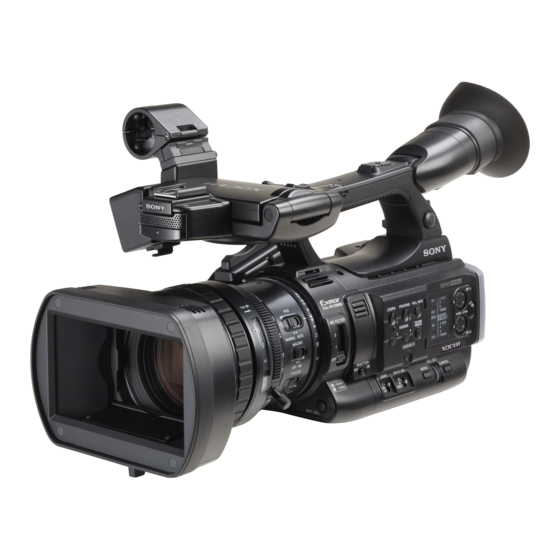
Part Identification For functions and usage, see the pages in parentheses. Camcorder PMW-200 Operation panel on the handle (page 15) Rear connector panel (page 17) Lens control block Side operation panel Card slot block (page 16) (page 15) (page 16) PMW-100 Operation panel on the handle (page 15) - Page 13 Lens hood Power switch (page 22) BATT RELEASE button (page 21) PMW-200 Attach Eyepiece focusing knob (PMW-100 only) Insert the hood by aligning it with the mark on (page 23) the camcorder and hood, and turn the hood DC IN connector (page 22) clockwise while facing the front of the camcorder (in the opposite direction of the Battery pack receptacle (page 21)
- Page 14 PMW-200 PMW-200 Controls on the grip (page 17) Viewfinder (page 23) LCD (Liquid Crystal Display) monitor (page 23) How to attach the EVF large eyecup Front accessory shoe PMW-200 Built-in microphone (page 46) Stretch the EVF large eyecup for attaching to the viewfinder and insert it aligning with the REC/TALLY lamp horizontal groove of the eyecup.
- Page 15 NEXT (clip directional jump) button (page 68) DISPLAY button (page 19) VOLUME (monitor volume) buttons (page 47) CANCEL button DURATION/TC/U-BIT (time data Eyepiece focusing knob (PMW-200 only) selection) button (page 45) (page 23) REC START/STOP button (page 38) Microphone cable holder (PMW-200 only) REC HOLD lever (page 38) (page 32) Lens control block (PMW-200 only)
- Page 16 It functions accordingly when you turn it up or Side operation panel down, or you push it horizontally. It is called the “jog dial” in the subsequent operating instructions. CANCEL button Card slot block The SxS memory card slots and EJECT buttons are located behind the cover.
- Page 17 Rear connector panel Controls on the grip PMW-200 Behind the cover USB connector (Mini B) i.LINK (HDV/DV) connector (4-pin, S400 PMW-200 conforming to IEEE1394) (page 105) REC REVIEW button (page 38) A/V OUT connector (audio/video multi output) (page 106) Power zoom lever (page 43) HDMI OUT connector (page 105) EXPANDED FOCUS button (page 43) SDI OUT connector (BNC type) (page 105)
-
Page 18: Ir Remote Commander (Supplied)
Backup battery holder (page 122) IR Remote Commander (Supplied) The buttons without remarks can be used in the same manner as the corresponding buttons on the camcorder. PUSH SET SHOTMARK ZOOM THUMBNAIL SUB CLIP PREV PLAY/PAUSE NEXT STOP > FREV FFWD REC PAUSE PUSH AF... -
Page 19: On-Screen Indications
On-Screen Indications While recording (or standing by to record), pressing the DISPLAY button displays the statuses and settings of this unit on the LCD monitor/viewfinder screen. Remarks [M]: The indication of the items named with this suffix can be independently turned on/off with “Display On/Off”... -
Page 20: Direct Menu Operation
Wide-conversion lens setting indicator [M] Clip name indication [M] (page 38) (page 87) Displayed when Wide Conversion of the Direct Menu Operation CAMERA SET menu is set to “On”. Synchronous recording display [M] The settings of the items named with a suffix [D] (page 105) can be changed using the Direct menu on the Displayed when “SDI Rec Control”... -
Page 21: Preparations
Checking battery charge remaining AC adaptor. When recording or playback is in progress on the For safety, use only the Sony battery packs and battery pack, an icon to show the current battery AC adaptor listed below: charge level and usage time remaining are... -
Page 22: Using Ac Power (Dc In Power)
Using AC Power (DC IN Power) Setting the Clock Connection example: when connecting BC-U1 When you turn the camcorder on for the first time after purchasing or replacing the backup battery (page 122), the Initial Setting display appears on the LCD monitor/viewfinder screen. Set the date and time of the built-in clock, using this display. -
Page 23: Adjusting The Lcd Monitor And Viewfinder
Turning the EVF on/off Adjusting the LCD With the factory setting, the EVF is turned on Monitor and Viewfinder when the LCD monitor is in its park position or is rotated to face the subject. You can change the setting so that the EVF is always on regardless of the status in the LCD Adjusting the LCD Monitor monitor, using “EVF”... -
Page 24: Using The Ir Remote Commander
Replacing the battery in the IR Remote Using the IR Remote Commander Commander Use a commercially available CR2025 lithium battery. Do not use any battery other than a CR2025. Before use Hold down the lock lever 1, pull out Before you use the supplied IR Remote the battery holder 2, and remove the Commander for the first time, pull out the battery. -
Page 25: Using Sxs Memory Cards
Lights in Standby (ready for recording or green playback using the loaded SxS memory SxS, SxS PRO and SxS-1 are trademarks of Sony card) Corporation. • No SxS memory card is loaded. The ExpressCard word mark and logo are owned •... -
Page 26: Switching Between Sxs Memory Cards
Switching Between SxS Memory Checking the Remaining Time Cards Available for Recording When SxS memory cards are loaded in both card While recording (or standing by to record), you slots A and B, press the SLOT SELECT button can check the time remaining for the SxS memory (page 16) to select the card you wish to use. -
Page 27: Using An External Hard Disk
During restoration, the in-progress message and status bar (%) are displayed, and the ACCESS Using an External Hard lamp is lit in red. Disk When restoration is completed, the completion message is displayed for three seconds. If restoration fails You can use an optional PHU-220R Professional •... -
Page 28: Formatting The Phu-220R
Fit the bottom plate (spring type) into Formatting the PHU-220R the auxiliary shoe. For a PHU-220R that is not formatted or that was Slits for screw holes formatted with another system, the message “Unsupported File System” is displayed on the Bottom plate LCD monitor/EVF screen. -
Page 29: Using Other Media
To restore the hard disk Using Other Media Select “Execute” via the up/down/left/right buttons or the jog dial, then press the SEL/ SET button or the jog dial. XQD Memory Cards During restoration, an in-progress message and status bar (%) are displayed, and the ACCESS By using an optional QDA-EX1 Media Adaptor, lamp is lit in red. -
Page 30: Memory Stick" Media/Sdhc Cards
• “Storing/Retrieving the Setting Data” (page Formatting When you use a “Memory Stick” or an SDHC The following Sony USB flash drives are card with this camcorder, formatting is required. recommended for use with this camcorder. A “Memory Stick” or an SDHC card to be used •... - Page 31 Formatting (Initializing) USB Flash are trademarks of Drives Sony Corporation. • “XQD” is a trademark of Sony Corporation. USB flash drives must be formatted with the FAT32 file system. Note Before using a drive, format it on this camcorder or a PC.
-
Page 32: Using A Wi-Fi Adapter (Pmw-200 Only)
Insert the protrusion on the back of the Using a Wi-Fi Adapter CBK-WA01 into the hole on the Wi-Fi adapter fixing bracket, and tighten the (PMW-200 only) screw to fix the CBK-WA01 to the bracket. Mounting an optional CBK-WA01 Wi-Fi Adapter on this camcorder allows a Wi-Fi connection between a computer and the camcorder. -
Page 33: Making A Wi-Fi Connection
Depending on the microphone used, a humming/ To make a connection in ad hoc mode buzzing noise may be recorded. In this case, inserting the cable of the external microphone Refer to “Settings on the Computer” into the cable clamp (page 46), which is located under “Making a Wi-Fi Connection to under the AUDIO IN CH-1/CH-2 connectors, Your Computer (Ad hoc Mode)”... -
Page 34: Using The Web Menu
To find and connect to a wireless LAN from the Set the Key item to the network key (or camcorder security key) set on the computer and Perform the same procedure in “To make a press the SEL/SET button or the jog connection in ad hoc mode”... -
Page 35: Using The Wi-Fi Remote Commander
Note Using the Wi-Fi Remote The configuration of items displayed in the Web Commander menu varies depending on the browser you are using. When a Wi-Fi connection is established between a device such as smartphone, tablet, PC, etc., and To display the Web menu the camcorder, the Wi-Fi remote commander appears on the device screen and the device can Launch a browser on the computer, and... - Page 36 To display the Wi-Fi remote commander Compatible devices To display the Wi-Fi remote commander on a The following devices, using the specified device screen, settings are required on both the versions or higher, can be used as Wi-Fi remote device and camcorder. commanders.
-
Page 37: Recording
Recording Basic Operation Procedure Preparing the lens cap PMW-200 7, 8 REC START/STOP REC REVIEW (on the grip) Power switch: ON (the " position) LCD monitor Battery pack insertion angle adjustment FULL AUTO SxS memory card slots When using the remote commander, activate the Preparations remote control mode (page 24). - Page 38 To delete clips “White Balance” on page 40 You can delete the last recorded clip by using the Note Last Clip DEL function (page 61). Use the All AF (Auto Focus) is not activated by setting the Clips DEL function (page 61) to delete all camcorder to Full Auto mode.
-
Page 39: Changing Basic Settings
Note Changing Basic Settings If copying is done using Explorer (Windows) or Finder (MAC), the continuity and relationships of recorded materials may not be maintained. You can make changes to the settings based on Maximum duration of a clip the intended usage of the recorded video or The maximum clip length is 24 hours for FAT recording conditions. -
Page 40: White Balance
Clear: ND filter not used The B position of the WHITE BAL switch is assigned to ATW mode at the factory. The setting can be changed with “White Switch <B>” (page White Balance 86) in the CAMERA SET menu to select Memory B mode. -
Page 41: Markers/Zebra Patterns
(page 19). 3 seconds. If the error message continues to be When the Direct menu is in All mode, you can displayed after several attempts, consult your Sony change the gain in steps of 3 dB with the Direct service representative. -
Page 42: Iris (Pmw-200) / Exposure (Pmw-100)
Setting with the Direct menu setting “Auto Shutter” in “TLCS” (page 86) in the When you press the DISPLAY button, the current CAMERA SET menu to “On.” shutter mode and the set value are displayed (page 19). Iris (PMW-200) / Exposure (PMW- When the Direct menu (page 20) is in All mode, 100) you can change the shutter mode and speed with... -
Page 43: Zoom
When using a lens remote controller Zoom (PMW-200 only) Operating Zoom manually Zooming can also be controlled from an optional lens remote controller connected via the LENS PMW-200: Setting the ZOOM switch (page 17) REMOTE connector. on the bottom of this unit to the MANUAL For operation, refer to the operation guide of the lens position sets to manual zoom mode. -
Page 44: Steady Shot
Peaking Adjusting in AF Mode When you press the PEAKING button, the AF (Auto Focus) mode adjusts the focus peaking function is activated. This function emphasizes the contours of the images on the automatically. PMW-100: Set the FOCUS switch (page 16) to LCD monitor/EVF screen, making manual AUTO. -
Page 45: Nightshot (Pmw-100 Only)
NightShot (PMW-100 only) Time Data NightShot is convenient for recording in dark Setting the Timecode areas. Set “Setting” in “NightShot” (page 87) in the Specify the timecode to be recorded with CAMERA SET menu to “On.” “Timecode” and “TC Format” in the TC/UB SET You can also assign NightShot to an assignable menu (page 94). -
Page 46: Recording Audio Signals
Connect the microphone cable to the Recording Audio Signals AUDIO IN CH-1/CH-2 connectors. Four channels (CH-1/CH-2/CH-3/CH-4) of audio can be recorded (Linear PCM recording) in synchronization with video recording. You can use the built-in stereo microphones (omni-directional electret condenser microphones) or 2-channel external audio inputs to the AUDIO IN connectors by switching with the AUDIO IN switches. -
Page 47: Monitoring The Audio
To adjust the levels manually Useful Functions Set the AUDIO SELECT switches CH-1 and CH- 2 to MANUAL and adjust the audio recording levels by turning the AUDIO LEVEL knobs Color Bars/Reference Tone (page 16). Set the controls to 5 for the reference setting (0 By setting “Camera/Bars”... -
Page 48: Ok/Ng/Kp Flags (For Udf Only)
an assignable button (page 49), you can also use Adding the OK mark that button. When recording of a clip ends, press the For operations to add shot marks after recording, see “Adding Shot Marks During Playback (UDF and assignable button to which you assigned the FAT HD Mode)”... -
Page 49: Assignable Buttons
• The Setup and PICTURE PROFILE menus cannot be • Interval Recording mode cannot be used when the operated during Rec Review. items “DVCAM” or “HDV” are set for “SDI/HDMI/ i.LINK I/O Select” (page 90) in the VIDEO SET menu, and the video format of “Format” in “System” Assignable Buttons (page 99) in the OTHERS menu is set to other than “HQ mode/23.98P.”... -
Page 50: Clip Continuous Recording (Udf Only)
• Frame Recording mode cannot be used when the items by using the Clip Continuous Recording function, “DVCAM” or “HDV” are set for “SDI/HDMI/i.LINK which will add recordings to the same clip until I/O Select” (page 90) in the VIDEO SET menu, and the function is disabled or turned off. -
Page 51: Picture Cache Recording: Retroactively Record
Restricted Operations Performing Picture Cache Recording If you perform any of the following operations while recording or standing by to record, 1 Press the REC START/STOP button. continuous clip will not be created. The next time Recording begins, and stored video in the cache you start recording, a new clip will be created. -
Page 52: Freeze Mix: Image Alignment
Notes Freeze Mix: Image Alignment • Slow & Quick Motion recording cannot be used in SD Mode. In UDF HD Mode or FAT HD Mode, an image • Slow & Quick Motion cannot be set to “On” (still picture) of a recorded clip can be simultaneously with Frame Recording, Interval Recording, Picture Cache Recording, or Clip temporarily superimposed on the current camera... -
Page 53: Automatic Adjustment Of Flange Focal Length (Pmw-200 Only)
If you press the CANCEL button during Automatic adjustment of flange adjustment focal length (PMW-200 only) Automatic adjustment of the flange focal length is aborted and the condition before starting the When automatic adjustment of flange focal adjustment is resumed. length is activated, focusing is performed both at If the adjustment fails the wide-angle and telephoto ends of the zoom for... - Page 54 When the settings have been made, press the PICTURE PROFILE button. Selecting a registered Picture Profile Once you store a picture profile, you can recall the picture quality registered in the picture profile. While standing by to record, press the PICTURE PROFILE button (page 16).
-
Page 55: Picture Profile Items
Picture Profile Items The values when “Off” is selected at “SEL” of the PICTURE PROFILE menu are shown in bold face (example: Standard PICTURE PROFILE SET Items Subitems and setting values Contents Profile Name Profile name Set the profile name in 8 characters at maximum. Standard You can use upper- and lowercase alphabetics, Changing the picture profile... - Page 56 PICTURE PROFILE SET Items Subitems and setting values Contents Color Correction Setting Set to “On” to enable the color phase adjustment On / Off for a specific area. (Simultaneous adjustment of (PMW-200 only) multiple areas is not allowed. You can adjust it for Adjusting the color phase in one area only.) a specific area (Unselectable...
- Page 57 PICTURE PROFILE SET Items Subitems and setting values Contents HD Detail Setting Set to “On” to apply the details to the video signal. On / Off Adjusting the details to be applied to the picture in HD Level Adjust the detail level. Mode –99 to +99 (±0) Frequency...
-
Page 58: Sd Detail
PICTURE PROFILE SET Items Subitems and setting values Contents SD Detail Setting Set to “On” to apply the details to the video signal. On / Off Adjusting the details to be applied to the picture in SD Level Adjust the detail level. Mode –99 to +99 (±0) Frequency... - Page 59 PICTURE PROFILE SET Items Subitems and setting values Contents Width Adjust the width of the color phase of the target 0 to 90 (40) area for Skin Tone Detail control. Note When Area Detection is executed, the Width setting automatically returns to 40. Aperture Setting Set to “On”...
- Page 60 PICTURE PROFILE SET Items Subitems and setting values Contents Black –99 to +99 (±0) Adjust the master black level. Adjusting the black Black Gamma –99 to +99 (HD: ±0, SD: -16) Adjust the level of black gamma function that emphasizes only the dark areas of the picture to Adjusting the black gamma clear the tones or on the contrary de-emphasizes it level...
-
Page 61: Deleting Clips
Note Deleting Clips Values for “Clock Set” and “Hours Meter” in the OTHERS menu are not stored. While standing by to record, the Last Clip DEL function for deleting the last recorded clip and the Storing the Setup file All Clips DEL function for deleting all clips from an SxS memory card are available. -
Page 62: Planning Metadata
Even if the total number of planning metadata files is 64 or less, all of the planning metadata files may not appear if the directory where they are located on the USB flash drive (General/Sony/Planning) contains 512 or more files. You can shoot using clip names and shot mark... - Page 63 Using the Wi-Fi connection UTF-8"?>3 When connecting the unit with a computer via <PlanningMetadata xmlns="http:// Wi-Fi, the file transmission can be done accessing xmlns.sony.net/pro/metadata/ the unit’s Web menu from a computer. planningmetadata" assignId=" P0001" creationDate=" Launch the browser and input http:// 2011-08-20T17:00:00+09:00"...
- Page 64 Note If a name string contains even one non-ASCII character, the maximum length of that string is limited to 16 characters. <?xml version="1.0" encoding=" UTF-8"?>3 <PlanningMetadata xmlns="http:// xmlns.sony.net/pro/metadata/ planningmetadata" assignId=" H00123" creationDate=" 2011-04-15T08:00:00Z" lastUpdate=" 2011-04-15T15:00:00Z" version= "1.00">3 <Properties propertyId= "assignment"...
-
Page 65: Playback
Playback Thumbnail Screens When you press the THUMBNAIL button (page 15), clips recorded on the SxS memory card are displayed as thumbnails on the screen. If no clips are recorded on the card, a no-clip message is displayed. You can start playback from the clip selected on the thumbnail screen. The playback picture can be seen on the LCD monitor/EVF and external monitors. -
Page 66: Changing The Type Of Thumbnail Screen
FAT HD Mode Lock mark (UDF and FAT HD Mode only) The normal thumbnail screen, OK clip thumbnail UDF: A lock mark appears if the selected clip is screen, and All-Clip thumbnail screen are locked. cyclically displayed. FAT HD Mode: A lock mark appears if the FAT SD Mode selected clip has an OK mark. -
Page 67: Playing Clips
Information displayed on the playback Playing Clips screen The following information is superimposed on the playback picture. For playback operations, use the playback control buttons on the handle (page 15). When the IR Remote Commander is enabled, you can use its playback control buttons instead (page 24). -
Page 68: Monitoring Audio
Monitoring Audio Clip Operations In Normal playback mode, you can monitor the recorded audio signals through the built-in During thumbnail screen playback, etc., you can speaker (page 14) or connected headphones. operate the clips or confirm and change the With the headphones connected to the headphone subsidiary data for clips using the Clip Operation connector (page 13), the built-in speaker is turned menus. -
Page 69: Basic Operations Of The Clip Operation Menus
Expand Clip screen (page 73) Clip Operation menu on the thumbnail CANCEL screen EXPAND (COARSE) Pressing the SEL/SET button or the jog dial with EXPAND (FINE) the thumbnail screen (page 65) displayed calls the Clip Operation menu for the clip at the cursor. PAUSE Item Function... -
Page 70: Displaying The Detailed Information Of A Clip
Displaying the Detailed Information of a Clip Select “DISP CLIP INFO” from a Clip Operation menu. 120min CL I P I NFO 0011 / 0300 JPAN0011 ( 1 ) 01 / JAN / 2009 10 : 53 HQ 1920 / 23. 9 P S&Q Mot i on 29 / 24f p s TCR 00 : 05 : 00 : 02 TCR 00 : 05 : 00 : 00 STR... -
Page 71: Adding/Deleting A Flag (Udf Only)
Adding/Deleting a Flag (UDF Only) Copying Clips You can add an OK/NG/KP flag to clips recorded You can copy clips on an SxS memory card to in UDF. By adding flags, you can set the another SxS memory card. camcorder to display only clips with certain flag Each clip is copied with the same name to the settings on the thumbnail screen (OK/NG/KP/ destination SxS memory card. -
Page 72: Deleting Clips
EXPAND CLIP screen in UDF and FAT HD Deleting Clips Mode You can delete clips from the SxS memory card. Select “DELETE CLIP” from the Clip Operation Current frame number menu. 120min EXPAND CLIP 0000123 Note Clips with an OK mark and flagged clips set to LOCK 01 : 10 : 20 : 00 01 : 10 : 30 : 00 01 : 10 : 40 : 00... -
Page 73: Displaying The Shot Mark Screen (Udf And Fat Hd Mode)
EXPAND CLIP screen in FAT SD Mode Clip Operation menu on the EXPAND CLIP screen Current frame number UDF and FAT HD Mode When you select a frame on the EXPAND CLIP 120min EXPAND CLIP 0000001 screen and press the SEL/SET button or the jog dial, the Clip Operation menu pops up to enable 00 : 00 : 00 : 00 00 : 09 : 30 : 00... -
Page 74: Adding/Deleting Shot Marks (Udf And Fat Hd Mode)
SHOT MARK screen example (when ALL Item Function PAUSE To set to Pause mode at the selected MARKS is selected) frame SET INDEX PIC To specify the selected frame for the 120min SHOT SHOT MARK1 0031 / 0031 index frame of the clip (page 74) SHOT MARK1 To delete the shot mark 1 from the selected frame (page 74) -
Page 75: Dividing A Clip (Fat Hd Mode Only)
Dividing a Clip (FAT HD Mode Only) In FAT HD Mode, you can divide a clip into two different clips at the frame you select on the EXPAND CLIP screen (page 72) or the SHOT MARK screen (page 73). Select “DIVIDE CLIP” from the Clip Operation menu. -
Page 76: Status Displays
Status Displays Showing the Status Screens Zebra: Zebra status Press the STATUS button (page 15) to display status screens on the LCD monitor/EVF screen/ Display Contents external video monitor. “On” is displayed and the setting of Use the up/down buttons (page 15) or the jog dial “Zebra1 Level”... -
Page 77: Audio Status Screen
Audio Status Screen Video Status Screen Output CH: External output/headphone output Video Format Depending on the setting of “Output CH” in Video Format: Video format setting “Audio Output” in the AUDIO SET menu and the The number of vertical lines, frame rate, scan setting of “Monitor CH,”... -
Page 78: Battery/Media Status Screen
Battery/Media Status Screen Battery: Battery charge remaining The remaining charge level of the mounted battery pack is displayed. Charge Count: Repeated charge times The number of times that the mounted battery pack has been charged is displayed. HDD A/HDD B: Battery remaining of PHU-220R units When professional hard disk units are connected, the remaining power levels of the batteries of the... -
Page 79: Overview Of The Setup Menus
Menu Configuration and Detailed Settings Overview of the Setup Menus Press the MENU button to display setup menus Setup Menu Layers on the LCD monitor/EVF screen with settings necessary for recording and playback. (You can also display setup menus on an external monitor.) MENU Set items by selecting them from the following CAMERA SET... -
Page 80: Basic Menu Operations
VIDEO SET Input Source Select Basic Menu Operations SDI/HDMI/i.LINK I/O Select SDI/HDMI/Video Out Super Down Converter 23.98P Output Menu controls SDI Rec Control MENU button (page 15) LCD/VF SET To turn Menu mode to use Setup menus on/off. Up/Down/Left/Right buttons, SEL/SET button Peaking (page 15) Marker... - Page 81 Setting the Setup menus Entering a character string Rotate the jog dial or press the up/down/left/right When you select an item for which a character buttons to set the cursor to the icon of the menu string, such as a time value or filename, is to be you wish to set, then push the jog dial or SEL/ specified, the input area for the character string is SET button to select that menu.
-
Page 82: Setup Menu List
Setup Menu List The functions and available settings of menus are listed below. The default settings set at the factory are shown in bold face (example: ). The items marked with Speed [M] in the Menu items column cannot be set while displaying the thumbnail screen or during playback operations. - Page 83 CAMERA SET Menu items Subitems and setting values Contents SLS/EX SLS Setting Set the number of cached frames. OFF / 2 / 3 / 4 / 5 / 6 / 7 / 8 / (PMW-100 only) Notes 16 / 32 / 64 Setting the Slow •...
- Page 84 CAMERA SET Menu items Subitems and setting values Contents Flicker Reduce Mode Set the operation of the Flicker-Reduction function. Auto / On / Off On: To always activate it Setting Flicker Auto: To automatically activate it when flicker is detected. Compensation Off: To not activate it Notes...
- Page 85 CAMERA SET Menu items Subitems and setting values Contents Interval Rec Setting Turn the Interval Recording function on/off. On / Off Setting the Interval Recording Interval Time Set the interval of recording in Interval Recording. function 1 to 10/15/20/30/40/50 sec 1 to 10/15/20/30/40/50 min 1 to 4/6/12/24 hour Number of Frames...
- Page 86 CAMERA SET Menu items Subitems and setting values Contents TLCS Level Set the target level (to make brighter or darker) of auto iris +1.0 / +0.5 / ±0 / –0.5 / –1.0 (PMW-200)/auto exposure (PMW-100) control in TLCS. Setting the Total (This setting also affects the gain control in AGC mode and Level Control shutter-speed control in Auto Shutter mode.)
- Page 87 CAMERA SET Menu items Subitems and setting values Contents ATW Speed 1 / 2 / 3 / 4 / 5 Set the tracing speed of ATW. The larger the number you set, the speed becomes faster. Setting for Auto Tracing White Balance ATW Mode Natural / Pure...
-
Page 88: Audio Set Menu
AUDIO SET Menu AUDIO SET Menu items Subitems and setting values Contents Audio Input CH3 Input Source Set the audio signal source to be recorded for CH3 for a 4- Internal / External channel recordable format. Setting for audio Internal: Record the L side of the internal microphone for inputs CH3. - Page 89 AUDIO SET Menu items Subitems and setting values Contents CH1&2 AGC Mode Select auto tuning for the input level of an analog audio signal Mono / Stereo recorded to CH-1/CH-2. Mono: Perform for each channel. Stereo: Perform in stereo mode. CH3&4 AGC Mode Select auto tuning for the input level of an analog audio signal Mono / Stereo / Off...
-
Page 90: Video Set Menu
VIDEO SET Menu VIDEO SET Menu items Setting values Contents Input Source Camera / i.LINK Select video and audio signal for the input source. Camera: Camera image Select i.LINK: HDV/DVCAM input via the i.LINK (HDV/DV) Setting the input connector source Notes •... -
Page 91: Lcd/Vf Set Menu
VIDEO SET Menu items Setting values Contents Down Squeeze / Letterbox / Edge Set the output mode (aspect) for SD signals Crop Squeeze: To horizontally reduce a 16:9 picture to output a 4:3 Converter picture Selecting the Letterbox: To mask the upper and lower areas of a 4:3 picture operation mode of to display a 16:9 picture in the center of the screen the down converter... - Page 92 LCD/VF SET Menu items Subitems and setting values Contents Marker Setting Turn all marker indications on/off in combination. On / Off Setting the markers added to Safety Zone Turn the safety marker on/off. pictures on the On / Off LCD monitor/EVF Safety Area Select the size (ratio to the entire screen) of the safety zone screen...
- Page 93 LCD/VF SET Menu items Subitems and setting values Contents Timecode Turn the time data (timecode, user bits, duration) indication On / Off on/off. Battery Remain Turn the battery remaining/DC input voltage indication on/ On / Off off. Media Remain Turn the media remaining indication on/off. On / Off TLCS Mode Turn the TLCS mode indication on/off.
-
Page 94: Tc/Ub Set Menu
TC/UB SET Menu TC/UB SET Menu items Subitems and setting values Contents Timecode Mode Set the timecode mode. Preset / Regen / Clock Preset: To start the timecode from the specified value Setting the Regen (regeneration): To continue the timecode during timecode recording only. - Page 95 TC/UB SET Menu items Subitems and setting values Contents TC Format DF / NDF Set the timecode format. DF: Drop frame Setting the time NDF: Non drop frame code format Note The current video format/frame frequency determines whether the mode is fixed either to DF or NDF (see below), regardless of the TC Format setting.
-
Page 96: Others Menu
When you select “Execute” to store the setting values to an Execute/Cancel SxS memory card, the setup file is stored to one of the Storing/recalling following directories. the menu settings For UDF: /General/Sony/PRO/CAMERA/XDCAM/ to an SxS memory PMW_xxx/ card or USB flash For FAT: /SONY/PRO/CAMERA/XDCAM_EX/PMW_xxx/ drive Recall Select “Execute”... - Page 97 OTHERS Menu items Subitems and setting values Contents Assign Button PMW-100: <1> to <4> Assign a function to the ASSIGN buttons 1/2/3/4. (The PMW-200: <1> to <5> selectable functions are shared.) Assigning Off / Zebra / Peaking / Marker / Off: No function functions to the Zebra: For turning the zebra function on/off...
- Page 98 OTHERS Menu items Subitems and setting values Contents Steady Shot: For turning the Steady Shot function on/off. Tally Front Set the brightness of the tally lamp. High / Low / Off High: To brighten the lamp Setting the tally Low: To dim the lamp lamps Off: To not light the lamp Hours Meter...
- Page 99 OTHERS Menu items Subitems and setting values Contents System Country Select the area of use and setup ON/OFF setting. NTSC Area / NTSC(J) Area / NTSC Area: Setup ON PAL Area NTSC(J) Area: Setup OFF PAL Area: Setup OFF Note The default setting is different among the sales areas.
- Page 100 OTHERS Menu items Subitems and setting values Contents Clip Auto Naming Select the method to specify clip names. C**** / Title / Plan C****: UDF only Setting for clip Title: To specify as desired by “Title Prefix” name or deletion Plan: To use a name specified in planning metadata (if no name is specified in planning metadata, the name specified by “Title Prefix”...
- Page 101 64 or less, all of the planning metadata files may not appear if the directory where they are located in the SxS memory card (General/Sony/ Planning) contains 512 or more files. • After you start loading, do not remove the SxS memory card until the completion message is displayed.
- Page 102 OTHERS Menu items Subitems and setting values Contents Properties Select “Execute” to display the detailed information of the Execute / Cancel planning metadata loaded in the camcorder. File Name: Filename Assign ID: Assignment ID Created: Time and date of creation Modified: Time and date of most recent modification Modified by: Name of person who modified the file Title1: Title1 specified in file (clip name in ASCII format)
- Page 103 OTHERS Menu items Subitems and setting values Contents MAC Address Display the MAC address. Net Config Reset Reset the “Network” settings to the preset values. Execute / Cancel Select “Execute” to reset. Wi-Fi Scan Networks Scan the available network connections when “Wi-Fi” is set Execute / Cancel to “Enable.”...
- Page 104 OTHERS Menu items Subitems and setting values Contents Version Vx.xx (PMW-200) The current software version of the camcorder is displayed. Vx.xx_1 (PMW-100) Showing the version of this unit Version (Lens) Vx.xx The current lens version of the camcorder is displayed. (PMW-100 only) Showing the version of the lens...
-
Page 105: Connecting External Monitors And Recording Devices
Connecting External Devices Connecting External Monitors and Recording Devices To display recording/playback pictures on an Notes external monitor, select the output signal and use • If you set “SDI/HDMI/i.LINK I/O Select” in the an appropriate cable for the monitor to be VIDEO SET menu to other than “HD SDI &... -
Page 106: Operating Clips With A Computer
(page 136). • Operation is not guaranteed with all computers. For support information for the driver, visit the following URL: http://www.sony.net/SxS-Support/ With a Windows computer, check that a Removable Disk appears in My Computer. This indicates normal status. With a Macintosh computer, an icon is displayed on the menu bar. - Page 107 To check the connection to the camcorder Note Do not select “Card Power Off” from the SxS memory Set the power switch to ON to turn on card icon displayed on the menu bar. the camcorder. A message prompting you to confirm that Using the application software you wish to enable the USB connection is To copy clips to the local disk of your computer,...
-
Page 108: Connecting Via I.link (Fat Only)
Recording the Camcorder Picture Connecting via i.LINK on an External Device (FAT only) While recording (or standing by to record), the picture being shot with this camcorder is output as When an HDV-compatible video format (SP an HDV or DVCAM stream via the i.LINK 1440/59.94i, SP 1440/50i, or SP 1440/23.98P) or (HDV/DV) connector. -
Page 109: Nonlinear Editing
Set “SDI/HDMI/i.LINK I/O Select” Nonlinear Editing (page 90) in the VIDEO SET menu to “HDV.” When the camcorder is displaying thumbnails or in playback mode, you can transfer an HDV Set “Input Source Select” (page 90) in stream to a nonlinear editing system connected the VIDEO SET menu to “i.LINK.”... -
Page 110: External Synchronization
External Synchronization Video format Valid reference signal HQ 1920/59.94i 1080/59.94i When multiple units of the camcorder are used in NTSC HQ 1920/29.97P the same shooting location, recording can be HQ 1920/23.98P made in synchronization with a specific reference (23.98P Output: 59.94i(2-3 signal, and the timecode can be matched among Pull Down)) all the units. - Page 111 About 10 seconds after locking, even if the reference timecode from the external device is Video format Valid reference disconnected, the external lock will be kept. signal HQ 1920/50i 1080/50i Notes HQ 1920/25P • Check that the reference timecode and the reference HQ 1440/50i video signal are in a phase relation that complies the SMPTE timecode standards.
-
Page 112: Important Notes On Operation
AC adaptors) is a consumable may be damaged. In such a case, stop using it part. and contact your dealer or a Sony service Power may not be supplied to the unit properly if representative. the pins of the battery terminal are bent or... - Page 113 Note on laser beams Laser beams may damage the CMOS image sensors. If you shoot a scene that includes a laser beam, be careful not to let the laser beam be directed into the lens of the camcorder. About the LCD panels The LCD panels are manufactured with In such cases, set the Flicker-Reduction function extremely high-precision technology that yields...
-
Page 114: Formats And Limitations Of Outputs
Formats and Limitations of Outputs Video Formats and Output Signals Output formats for the SDI OUT connector Serial digital signals from the SDI OUT connector are output depending on the settings of the setup menu and format of the clip being played. The output format is converted when using the settings in the following chart. - Page 115 When a thumbnail screen is displayed Output format “Format” in “System” in Setting of “SDI/HDMI/i.LINK I/O Select” in the VIDEO SET menu the OTHERS menu HD SDI & HD HDMI SD SDI & SD HDMI i HD422 50/1080/23.98P SD/59.94i 1920×1080/59.94i HD420 HQ/1080/23.98P HQ 1920/23.98P HQ 1440/23.98P...
- Page 116 Output formats from the HDMI OUT connector Serial digital signals from the HDMI OUT connector are output depending on the settings of the setup menu and format of the clip being played. The output format is converted when using the settings in the following chart. Note When the format is UDF HD Mode or FAT HD Mode and “SDI/HDMI/i.LINK I/O Select”...
- Page 117 When a thumbnail screen is displayed Output format Setting of “SDI/HDMI/i.LINK I/O Select” in the VIDEO SET menu “Format” in “System” in HD SDI & HD HDMI SD SDI & SD HDMI i SD HDMI P & HDV the OTHERS menu HD HDMI &...
- Page 118 When you play clips recorded with the NTSC system while the “Country” is set to “PAL Area.” Some frames may be deleted due to frame rate conversion. VIDEO OUT Output format Playback clip video format HD-Y Analog composite HD422 50/1080/59.94i 1920×1080/49.95i SD/50i HD420 HQ/1080/59.94i...
- Page 119 Output formats from the i.LINK I/O connector Serial digital signals from the i.LINK I/O connector are output in the following formats depending on the settings of the setup menu and format of the clip being played. Note When “SDI/HDMI/i.LINK I/O Select” in the VIDEO SET menu is set to “HD SDI & HD HDMI,” “SD SDI & SD HDMI i,”...
-
Page 120: Limitations Of Inputs/Outputs
Limitations of Inputs/Outputs The outputs from the camcorder are limited by the menu settings as follows: ×: no signal Menu setting Output Input System SDI/HDMI/ HDMI i.LINK VIDEO A/V Out i.LINK i.LINK I/O UDF/ HD/SD Select HD SDI & HD ×... - Page 121 Menu setting Output Input System SDI/HDMI/ HDMI i.LINK VIDEO A/V Out i.LINK i.LINK I/O UDF/ HD/SD Select HD SDI & HD × × × × × × HDMI SD SDI & SD × Composite Composite × HDMI i HD HDMI & ×...
-
Page 122: Backup Battery Replacement
Backup Battery Replacement 0 2 5 C R 2 This camcorder uses a backup battery to retain various setting data. A lithium battery (CR2032) for backup is Insert a new backup battery (CR2032) mounted in the camcorder at the factory. with the + symbol on the battery facing The backup battery retains the date, time, and outside. -
Page 123: Troubleshooting
Troubleshooting Power Symptoms Cause Remedy The camcorder does not No battery pack is mounted and no Mount a battery pack (page 21) or connect to AC power on when you set power is supplied to the DC IN power using the BC-U1 or BC-U2 (page 22). the power switch to ON. -
Page 124: External Devices
External Devices Symptoms Cause Remedy The equipment connected It sometimes takes time for the Wait for about 15 seconds. If the connected to the camcorder via an connected equipment to recognize equipment still does not react, do the following: i.LINK connection does the operation. -
Page 125: Error/Warning Indications
Turn off the power and check the connected equipment, cables, and media. If they are not defective, turn on the power again. If the error persists, consult Sony service personnel. (If power cannot be turned off by setting the power switch to OFF, remove both the battery pack or the DC IN source.) - Page 126 Warning indication Buzzer Tally Cause and measures on LCD/EVF lamps Battery Error An error was detected with the battery pack. Please Change Battery Replace the battery pack with a normal one. Backup Battery End The remaining power of the backup battery is insufficient. Please Change Replace the battery with a new one.
- Page 127 Warning indication Buzzer Tally Cause and measures on LCD/EVF lamps Reached Clip Number The maximum number of clips for 1 memory card is reached, Limit so copying cannot continue. (xx/xx indicates the completed Copy Completed to xx/xx copy operations.) Replace the card. Not Enough Capacity There is not enough capacity for copying.
-
Page 128: Licenses
GPL version 2. The source code is provided on the internet. Use the following URL and follow the download instructions. http://www.sony.net/Products/Linux/common/ search.html We would prefer that you do not contact us about the contents of the source code. -
Page 129: About Openssl
5. Products derived from this software About OpenSSL may not be called "OpenSSL" nor may "OpenSSL" appear in their names without prior written permission of the OpenSSL Project. Because it uses the OpenSSL Toolkit, this product uses software developed by the OpenSSL 6. - Page 130 ============================ 1. Redistributions of source code must ======= retain the copyright notice, this list of conditions and the following This product includes cryptographic disclaimer. software written by Eric Young 2. Redistributions in binary form must (eay@cryptsoft.com). This product reproduce the above copyright includes software written by Tim notice, this list of conditions and the Hudson (tjh@cryptsoft.com).
- Page 131 OTHERWISE) ARISING IN ANY WAY OUT OF THE USE OF THIS SOFTWARE, EVEN IF ADVISED OF THE POSSIBILITY OF SUCH DAMAGE. The licence and distribution terms for any publically available version or derivative of this code cannot be changed. i.e. this code cannot simply be copied and put under another distribution licence [including the GNU Public Licence.]...
-
Page 132: Specifications
length from the tip of a front Specifications microphone to the back of the unit.) Power requirements DC 12 V (11.0 V ~ 17.0 V) General Power consumption Approx. 12 W Mass while recording with LCD Off, EVF PMW-200 On and I/O Select Off Approx. - Page 133 1440 × 1080/59.94i, 50i, 29.97p, 25p, HQ 1920 mode: MPEG-2 MP@HL, 23.98p 35Mbps / VBR HQ 1280 mode: MPEG-2 MP@HL, HQ 1440 mode: MPEG-2 MP@HL, 35Mbps / VBR 35Mbps / VBR 1280 × 720/59.94p, 50p, 29.97p, 25p, HQ 1280 mode: MPEG-2 MP@HL, 23.98p 35Mbps / VBR SP 1440 mode: MPEG-2 MP@H-14,...
-
Page 134: Lens
When using SBP-64 / SBS-64G1A Filter thread (64GB): Approx. 280 minutes M 77 mm, pitch 0.75 mm When using SBP-32 / SBS-32G1A Macro (32GB): Approx. 140 minutes ON/OFF possible When using SBP-16 (16GB): Approx. 70 minutes DVCAM mode PMW-100 When using SBP-64 / SBS-64G1A Lens mount (64GB): Approx. -
Page 135: Inputs/Outputs
Minimum subject illumination SDI output PMW-200: 0.12 lx (typical) (1920 × BNC type (1), switchable with HD-SDI/ 1080/59.94i, F1.9, +18 dB, 64-frame SD-SDI accumulation) SMPTE292M/259M PMW-100: 0.40 lx (typical) (1920 × i.LINK 1080/59.94i, F1.8, +18 dB, 64-frame IEEE 1394, 4-pin connector (1), HDV accumulation) (HDV 1080i) / DV input/output, S400 Shutter speed... -
Page 136: Displays
PMW-100: 0.24-inch color LCD: 392 application software, where applicable, from the (H) × 224 (V), 16:9 Sony Professional products web site. LCD monitor Sony Professional products web site homepage: 3.5-inch color LCD monitor: 852 (H) × U.S.A. http://pro.sony.com 3 (RGB) × 480 (V), 16:9 Canada http://www.sonybiz.ca... - Page 137 ANY OTHER MEDIA OR STORAGE SYSTEMS TO RECORD CONTENT OF ANY TYPE. • Always verify that the unit is operating properly before use. SONY WILL NOT BE LIABLE FOR DAMAGES OF ANY KIND INCLUDING, BUT NOT LIMITED TO, COMPENSATION OR REIMBURSEMENT...
-
Page 138: Index
Index Camera Data CAMERA SET Menu CAMERA Status Screen Numerics Charge Count 23.98P Output 38, 67, 100, 106 Clip 50, 85 Clip Cont. Rec Clip Name Disp A/V OUT connector Clip name AC Adaptor Clip Operation menu AC Power Clock ACCESS lamps Clock Set AGC mode... - Page 139 42, 87 Exposure ExpressCard slot Knee External Hard Disk KP Flag External Input Signals External Monitors External Synchronization Language eyepiece focusing knob 23, 91 LCD/VF SET Menu Lens hood Flange focal length LENS REMOTE connector 45, 84 Flicker Reduce Limitations of Inputs/Outputs Flickers Low Key SAT Focus...
- Page 140 SLS/EX SLS Status Screens P.Cache Rec Steady Shot 73, 74 PAUSE SxS Device Driver Software 44, 91 Peaking SxS Memory Cards PEAKING button System PHU-220R Picture Cache Recording Picture Profiles Tally 62, 101 Plan.Metadata TC Format Planning metadata TC IN connector PLAY/PAUSE button TC Out Power Zoom...
- Page 141 44, 87 Wide Conversion wide-conversion lens Wi-Fi Wi-Fi Adapter Wi-Fi remote commander XQD Memory Cards 41, 92 Zebra zebra pattern Zoom 43, 84 Zoom Speed Zoom Transition Index...
Need help?
Do you have a question about the PMW-100 and is the answer not in the manual?
Questions and answers