Sony PMW-150 Operating Instructions Manual
Solid-state memory camcorder
Hide thumbs
Also See for PMW-150:
- Operating instructions manual (131 pages) ,
- Service manual (132 pages) ,
- Getting started (2 pages)
Table of Contents

Related Manuals for Sony PMW-150


Summary of Contents for Sony PMW-150
-
Page 1: Operating Instructions
4-448-842-25(1) Solid-State Memory Camcorder PMW-150 Operating Instructions Before operating the unit, please read this manual and the more detailed manual on the CD-ROM and retain it for future reference. Printed in China © 2012 Sony Corporation... - Page 2 E3 (urban outdoors), E4 (controlled EMC environment, ex. TV studio). This product has been manufactured by or on behalf of Sony Corporation, 1-7-1 Konan Minato-ku Tokyo, 108-0075 Japan. Inquiries related to product compliance based on European Union legislation shall be...
- Page 3 Bateria de Íon-Lítio For the customers in the U.S.A. Atenção: SONY LIMITED WARRANTY - Please visit Se a bateria não for manuseada http://www.sony.com/psa/warranty for corretamente, ela poderá explodir, causar important information and complete terms incêndio ou até mesmo queimaduras and conditions of Sony’s limited warranty químicas.
- Page 4 Support.do pour obtenir les informations AVERTISSEMENT importantes et l’ensemble des termes et Une pression acoustique excessive en conditions de la garantie limitée de Sony provenance des écouteurs ou du casque applicable à ce produit. peut provoquer une baisse de l’acuité...
- Page 5 (kommerzieller und in beschränktem Maße industrieller Bereich), E3 (Stadtbereich im Freien) und E4 (kontrollierter EMV-Bereich, z.B. Fernsehstudio). Dieses Produkt wurde von oder für Sony Corporation, 1-7-1 Konan Minato-ku Tokio, 108-0075 Japan hergestellt. Bei Fragen zur Produktkonformität auf Grundlage der Gesetzgebung der Europäischen Union kontaktieren Sie bitte...
-
Page 6: Table Of Contents
Table of Contents Overview Part Identification ..............8 Camcorder ..............8 Preparations Power Supply ................13 Using a Battery Pack ............ 13 Using AC Power (DC IN Power) ......... 14 Turning the Power On/Off ........... 14 Setting the Clock ..............14 Adjusting the LCD Monitor and Viewfinder ....... - Page 7 Appendices Specifications ................26 General ................. 26 Lens ................28 Camera Block ............... 28 Inputs/Outputs .............. 28 Displays ................ 29 Internal Microphone ............. 29 Media Slot Block ............29 Package Configuration ..........29 Optional Accessories ............ 30 Table of Contents...
-
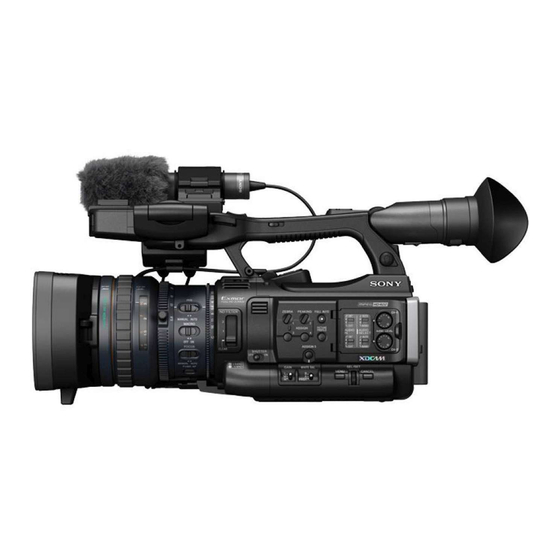
Page 8: Part Identification
Overview Part Identification For functions and use, see the operating instructions (PDF). Camcorder Operation panel on the handle Rear connector panel Lens control block Side operation panel Card slot block Lens hood Headphone connector (stereo mini jack) Rear IR remote control receptor Power switch BATT RELEASE button DC IN connector... - Page 9 Controls on the grip Viewfinder Operation panel on the handle Rear accessory shoe External microphone holder Microphone cable holder Hooks for the shoulder strap LCD (Liquid Crystal Display) monitor Front accessory shoe Built-in microphone REC/TALLY lamp Front IR remote control receptor Built-in speaker AUDIO IN CH-1/CH-2 connectors (XLR) and input selection (LINE/MIC/...
- Page 10 On-handle ZOOM button Side operation panel Zoom speed switch F FWD (fast forward) button LCD BRIGHT (LCD brightness adjustment) button NEXT (clip directional jump) button DISPLAY button VOLUME (monitor volume) buttons CANCEL button DURATION/TC/U-BIT (time data selection) button REC START/STOP button REC HOLD lever 12 13 14 15 16 Lens control block...
- Page 11 HDMI OUT connector Card slot block External device connector The SxS memory card slots and EJECT buttons SDI OUT connector (BNC type) are located behind the cover. TC IN (timecode input)/TC OUT (timecode output) connector (BNC type) Open the cover IN/OUT (input/output change) switch Set this to IN to select GENLOCK IN, and set this to OUT to select TC OUT and...
- Page 12 Bottom Tripod receptacles Note Check that the size of the hole matches the screw of the tripod. If they do not match, the camcorder cannot be attached to the tripod securely, and this may lead to the physical injury of the camera operator.
-
Page 13: Power Supply
Checking battery charge remaining AC adaptor. When recording or playback is in progress on the For safety, use only the Sony battery packs and battery pack, an icon to show the current battery AC adaptor listed below: charge level and usage time remaining are... -
Page 14: Using Ac Power (Dc In Power)
Using AC Power (DC IN Power) Setting the Clock Connection example: when connecting BC-U1 When you turn the camcorder on for the first time after purchasing or replacing the backup battery (“Appendices” in operating instructions (PDF)), the Initial Setting display appears on the LCD monitor/viewfinder screen. -
Page 15: Adjusting The Lcd Monitor And Viewfinder
You can change the setting so that the EVF is always on regardless of the status in the LCD Adjusting the LCD monitor, using “EVF” (“Menu Configuration and Monitor and Viewfinder Detailed Settings” in operating instructions (PDF)) in the LCD/VF SET menu. Change the “Power”... -
Page 16: Using The Ir Remote Commander
ATTENTION Using the IR Remote Il y a danger d’explosion s’il y a remplacement Commander incorrect de la batterie. Remplacer uniquement avec une batterie du même type ou d’un type équivalent recommandé par le constructeur. Lorsque vous mettez la batterie au rebut, vous To use the IR Remote Commander devez respecter la législation en vigueur dans le For controlling the camcorder from the IR... -
Page 17: Using Sxs Memory Cards
SxS memory card. green playback using the loaded SxS memory card) SxS, SxS PRO and SxS-1 are trademarks of Sony • No SxS memory card is loaded. • The loaded card is invalid. Corporation. • An SxS memory card is loaded, but The ExpressCard word mark and logo are owned another slot is active. -
Page 18: Switching Between Sxs Memory Cards
Notes Switching Between SxS Memory • Use the format function of this camcorder to format Cards SxS memory cards for use on this camcorder. The formats of cards formatted on other devices are not recognized as valid formats, making it necessary to When SxS memory cards are loaded in both card format them again on this camcorder. - Page 19 To restore a card Select “Execute” by pressing the up/down/ left/right buttons or turning the jog dial, then push the SEL/SET button or the jog dial. During restoration, the in-progress message and status bar (%) are displayed, and the ACCESS lamp is lit in red.
-
Page 20: Basic Operation Procedure
Recording Basic Operation Procedure LCD monitor angle adjustment 7, 8 REC START/STOP REC REVIEW (on the grip) Power switch: ON (the " position) Open the lens cap Battery pack insertion FULL AUTO SxS memory card slots Note Preparations When you hold the camcorder by the grip, support it from underneath with your left hand. - Page 21 “White Balance” (“Recording” in operating Checking the last recorded clip (Rec instructions (PDF)) Review) Note AF (Auto Focus) is not activated by setting the Press the REC REVIEW button. camcorder to Full Auto mode. The Rec Review function (“Recording” in For information of automatic focus adjustment, operating instructions (PDF)) is activated, see “Focus”...
- Page 22 Notes on Clips The maximum file size for a clip is 43 GB for UDF, 4 GB for FAT in HD Mode, and 2 GB for FAT in SD Mode. If you continue recording for an extended period, recorded materials may be segmented into multiple files, depending on the file size (the maximum number of partitions is 99).
-
Page 23: Overview Of The Setup Menus
Menu Configuration and Detailed Settings Overview of the Setup Menus Press the MENU button to display setup menus Setup Menu Layers on the LCD monitor/EVF screen with settings necessary for recording and playback. (You can also display setup menus on an external monitor.) MENU Set items by selecting them from the following CAMERA SET... -
Page 24: Basic Menu Operations
LCD/VF SET Basic Menu Operations Peaking Marker Zebra Display On/Off Menu controls TC/UB SET Timecode MENU button (page 9) Users Bit To turn Menu mode to use Setup menus on/off. OTHERS All Reset Up/Down/Left/Right buttons, SEL/SET button Camera Data (page 9) Time Zone When you press the up/down/left/right buttons, Clock Set... - Page 25 Setting the Setup menus Entering a character string Rotate the jog dial or press the up/down/left/right When you select an item for which a character buttons to set the cursor to the icon of the menu string, such as a time value or filename, is to be you wish to set, then push the jog dial or SEL/ specified, the input area for the character string is SET button to select that menu.
-
Page 26: Appendices
changes caused at zero-crossing): 3 A Appendices peak, 0.7 A r.m.s. (240V AC) Specifications Operating temperature 0°C ~ +40°C General Storage temperature –20°C ~ +60°C Mass Continuous operation time Approx. 2.2 kg (4 lb 14 oz) (While recording with LCD Off, EVF (Camcorder only) On and I/O Select Off) Approx. - Page 27 SD DVCAM mode: LPCM 16-bit, When using SBP-64B / SBS-64G1A 48 kHz, 4 channels (64 GB): Approx. 180 minutes SD DVCAM mode (for iLINK input): When using SBS-32G1A (32 GB): LPCM 16-bit, 48 kHz, 2 channels Approx. 90 minutes SD mode: DVCAM When using SBP-128B (128 GB): HD mode: LPCM 16-bit, 48 kHz, 4 Approx.
-
Page 28: Lens
3: 1/64ND Lens Minimum subject illumination 0.10 lx (typical) (1920 × 1080/50i, F1.6, Lens mount Fixed type +18 dB, 64-frame accumulation) Zoom ratio Shutter speed 20× 1/32 ~ 1/2000 sec. Maximum relative aperture Slow Shutter (SLS/EX SLS) 1:1.6 2, 3, 4, 5, 6, 7, 8, 16, 32, 64 frames Focal length Slow &... -
Page 29: Displays
SDI output Displays BNC type (1), switchable with HD-SDI/ SD-SDI Viewfinder SMPTE292M/259M 0.45-inch color LCD: 852 (H) × 480 (V), 16:9 i.LINK IEEE 1394, 4-pin connector (1), HDV LCD monitor (HDV 1080i) / DV input/output, S400 3.5-inch color LCD monitor: 852 (H) × 3 (RGB) ×... -
Page 30: Optional Accessories
Memo HVR-MRC1K* If you have lost or damaged the CD-ROM, you can purchase a new one from your Sony dealer or * To attach accessories to the rear accessory shoe, Sony service counter. use the optional cold shoe kit (part no.: X-2546- 633-1).
Need help?
Do you have a question about the PMW-150 and is the answer not in the manual?
Questions and answers