
Related Manuals for Emerson MicroCEM


Summary of Contents for Emerson MicroCEM
- Page 1 Instruction Manual 748467-A January 2002 Model MicroCEM Continuous Emissions Monitor http://www.processanalytic.com...
-
Page 2: Essential Instructions
The information contained in this document is subject to change without notice. Logos, trademarks and copyrights are property of their respective owners. Emerson Process Management Rosemount Analytical Inc. Process Analytic Division 1201 North Main Street... -
Page 3: Table Of Contents
Specifications ...1-19 1-12 500 Watts Power Supply ...1-20 a. Features ...1-20 1-13 MicroCEM Specifications...1-21 a. Analyzer ...1-21 b. Probe/Sample Handling ...1-22 Rosemount Analytical Inc. A Division of Emerson Process Management TABLE OF CONTENTS ...1-1 ...1-2 Instruction Manual 748467-A January 2002 Contents... - Page 4 Measurement Log File Format...3-18 e. Calibration Log File Format...3-19 Alarm Log File Format ...3-20 View Data Logs ...3-21 Viewing MicroCEM Data with a Web Browser ...3-23 a. Real-Time Page ...3-23 b. Emissions Page ...3-24 c. Download Page...3-26 Viewing MicroCEM Data with MS Excel...3-27 3-10 Auto Calibration ...3-28...
- Page 5 Model MicroCEM SOFTWARE ...4-1 Overview...4-1 MicroCEM User Interface Software...4-1 MicroCEM Web Server Software ...4-1 Software Development Management ...4-2 MAINTENANCE AND SERVICE ...5-1 Overview...5-1 Converter ...5-3 Ozone Generator...5-4 Personality Modules ...5-4 Chemiluminescense Detector Assembly...5-5 a. Reaction Chamber ...5-5 b. Photodiode ...5-5 TROUBLESHOOTING ...6-1...
- Page 6 Figure 3-1. Pocket PC ... 3-1 Figure 3-2. MicroCEM Front Panel ... 3-2 Figure 3-3. MicroCEM Pocket PC Display (Main Display Shown) ... 3-3 Figure 3-4. MicroCEM Menu ... 3-4 Figure 3-5. Pocket PC Alarms Screen ... 3-4 Figure 3-6.
- Page 7 Table 3-8. Calibration Log File Format ... 3-19 Table 3-9. Alarm Log File Format ... 3-20 Table 3-10. Average Period Selection ... 3-21 Rosemount Analytical Inc. A Division of Emerson Process Management LIST OF TABLES Instruction Manual 748467-A January 2002 Contents...
- Page 8 Instruction Manual 748467-A Model MicroCEM January 2002 Contents Rosemount Analytical Inc. A Division of Emerson Process Management...
-
Page 9: Preface
Model MicroCEM The purpose of this manual is to provide information concerning the components, functions, in- stallation and maintenance of the MicroCEM. Some sections may describe equipment not used in your configuration. The user should become thoroughly familiar with the operation of this module before operating it. Read this instruction manual completely. -
Page 10: Intended Use Statement
January 2002 INTENDED USE STATEMENT The MicroCEM Continuous Emissions Monitor is intended for use as an industrial process meas- urement device only. It is not intended for use in medical, diagnostic, or life support applications, and no independent agency certifications or approvals are to be implied as covering such applica- tions. - Page 11 This unit requires periodic calibration with a known standard gas. It also may utilizes a pressur- ized carrier gas, such as helium, hydrogen, or nitrogen. See General Precautions for Handling and Storing High Pressure Gas Cylinders, page P-5. Rosemount Analytical Inc. A Division of Emerson Process Management DANGER. TOXIC GAS WARNING.
- Page 12 Instruction Manual 748467-A Model MicroCEM January 2002 CAUTION. HEAVY WEIGHT Use two persons or a suitable lifting device to move or carry the instrument. Preface Rosemount Analytical Inc. A Division of Emerson Process Management...
-
Page 13: General Precautions For Handling And Storing High Pressure Gas Cylinders
8. Do not place cylinders where they may become part of an electric circuit. When electric arc welding, precautions must be taken to prevent striking an arc against the cylinder. Rosemount Analytical Inc. A Division of Emerson Process Management Instruction Manual 748467-A January 2002 °... -
Page 14: Documentation
Instruction Manual 748467-A January 2002 The following MicroCEM instruction materials are available. cal representative to order (See Section 8). 748467 Instruction Manual (this document) 748468 Instruction Manual, MicroCEM Sample Handling System This product may carry approvals from several certifying agencies. The certification marks appear on the product name-rating plate. -
Page 15: Section 1 Description And Specifications
Analysis Enclosure. The Analysis Enclosure shall be a standalone, computer-controlled unit, utilizing PC/104 as the system bus. The MicroCEM is enclosed in a rugged NEMA 4X, IP65 type enclosure, for harsh environ- ment. The analysis enclosure utilizes convec- tion cooling with no air intake and air vents. -
Page 16: C. Paramagnetic O 2
It has rugged self-tensioning suspension and is of welded non-glued construction. 1-4 DETECTOR METHODOLOGIES The MicroCEM can employ up to three differ- ent measuring methods depending on the configuration chosen. The methods are: NDIR, Paramagnetic O , Electrochemical O and Chemiluminescense. -
Page 17: Figure 1-1. Absorption Bands Of Sample Gas And Transmittance Of Interference Filters
This signal results from the cooling and heating of the pyroelectric detector mate- rial. 3000 Figure 1-1. Absorption Bands of Sample Gas and Transmittance of Interference Filters Rosemount Analytical Inc. A Division of Emerson Process Management 3200 3400 3600 3800 4000 4200... -
Page 18: Figure 1-2. Opto-Pneumatic Gas Detector
The Microflow sensor evaluates these flow pulses and converts them into elec- trical pulses which are processed into the corresponding analyzer output. Window Compensation chamber A Division of Emerson Process Management... -
Page 19: Figure 1-3. Overall Ndir Method
(reference side) Filter Cell Gas Detector Rosemount Analytical Inc. A Division of Emerson Process Management depending on the application and need for reduction of influences. Then the infrared radiation enters the analysis cells from which it is focused by filter cells onto the corresponding detector. -
Page 20: Paramagnetic Oxygen Method
The temperature sensor is used to control a heat ex- changer to warm the measuring gas to about 55 °C. Refer to Figure 1-4. Permanent Magnet Quartz Sphere(s) Wire Loop A Division of Emerson Process Management... -
Page 21: Electrochemical Oxygen Method
The rate of diffusion and corresponding response time (t90) of the sensor is dependent on the thickness of the Teflon membrane. Rosemount Analytical Inc. A Division of Emerson Process Management (Red) V out Thermistor (5) Resistor (6) -
Page 22: Figure 1-6. Electrochemical Oxygen Sensor
Lead Wire (Anode) Lead Wire (Cathode) Anode (Lead) O-Ring Plastic Disc Plastic Disk Resistor Thermistor Acid Electrolyte Sponge Disc Cathode (Gold Film) Teflon Membrane Figure 1-6. Electrochemical Oxygen Sensor Description and Specifications Rosemount Analytical Inc. A Division of Emerson Process Management... -
Page 23: Central Processing Unit
Power Supply: ... AT/ATX Connectors: ... COM1-4, SVGA, USB 1 and 2, PS/2 Mouse/Keyboard, ATX Power, Rosemount Analytical Inc. A Division of Emerson Process Management Embedded Enhanced Bios Award, 256KB Flash Bios.The Bios is immediately activated when you first turn on the system. -
Page 24: Analog/Digital I/O Board
PC/104 analog I/O board. The board can be user-configured in any of three ways: Channels 32 single-ended 8 differential, 16 single-ended 16 differential Rosemount Analytical Inc. A Division of Emerson Process Management Format... -
Page 25: Programmable Input Ranges
(to enable synchronization of multiple boards) and external A/D clock- ing. Rosemount Analytical Inc. A Division of Emerson Process Management Analog Outputs The ADIO board contains 4 12-bit analog outputs with autocalibration capability. Up to 5mA of output current per channel can be drawn from all channels simultane- ously. -
Page 26: Figure 1-9. Adio Block Diagram
Model MicroCEM ANALOG INPUTS 0-31 SE 0-15 DI ANALOG OUTPUTS 0-3 TIMING AND CONTROL SIGNALS HIGH CURRENT DRIVE 24 DIGITAL I/O BUFFER PORT A PORT B BUFFER PORT CH BUFFER PORT CL BUFFER ACK/STROBE A Division of Emerson Process Management... -
Page 27: Specifications
General purpose... 16-bit down counter (1 82C54 counter) General Power supply ... +5VD±10%@200mA typ Operating temperature ... -25 to +85°C Weight... 3.4oz/96g Rosemount Analytical Inc. A Division of Emerson Process Management (2 82C54 counters cascaded) Description and Specifications Instruction Manual 748467-A January 2002... -
Page 28: Pcmcia Adapter
Jumperless interrupt steering from PC Card to system. Complete set of device drivers complying with PCMCIA V2.1 /JEIDA V4.1, running under MS-DOS or MS-WINDOWS: • PCMCIA socket & card services drivers • Flash File System Rosemount Analytical Inc. A Division of Emerson Process Management... -
Page 29: Modem
The PC/104 Modular Modems support both dial-up and 2-wire leased-line. Figure 1-11 depicts the Modem. Figure 1-11. Modem Rosemount Analytical Inc. A Division of Emerson Process Management Instruction Manual Features V.90, 56 kbps data (560PC/104) V.34, 33.6 kbps data (336PC/104) 14.4 kbps fax... -
Page 30: Flash Drive
Commercial ... 3.3 V ± 5%, 5 V ± 10% Industrial ... 3.3 V ± 5%, 5 V ± 5% 1-16 Description and Specifications Figure 1-12. 128MB Flash Drive Rosemount Analytical Inc. Model MicroCEM A Division of Emerson Process Management... - Page 31 Thickness (Body) ... 9.6mm ± 5.0mm Thickness (Removable Edge) ... N/A Weight ... 160 g. max Mean Time Between Failures Rosemount Analytical Inc. A Division of Emerson Process Management Instruction Manual January 2002 500 µA @5.0 V 50 mA RMS @5.0 V 50 mA RMS @5.0 V...
-
Page 32: Pocket Pc
Instruction Manual 748467-A January 2002 1-10 POCKET PC The Pocket PC acts as an Graphic User Interface to the MicroCEM unit. Specifications Processor ... 133MHz 32-bit Hitachi SH3 processor Memory ... 32MB RAM, 16MB ROM Display ... 240 x 320 pixels LCD, Rich-color CSTN, backlit User Interface ... -
Page 33: Wireless Lan Adapter
1-11 WIRELESS LAN ADAPTER Wireless LAN adapter is an option to allow the user to remove the Pocket PC from the enclosure and to operate the MicroCEM from a distance up to 1000 feet. Figure 1-14 depicts the wireless LAN adapter. Specifications Data Rate ... -
Page 34: 500 Watts Power Supply
• Input Transient & ESD Compliance to EN61000-4-2/-3/-4/-5 • Fan Output Voltage and Optional Fan • Optional Isolation Diodes for Parallel or Redundant Operation 1-20 Description and Specifications Figure 1-15. 500 Watts Power Supply Rosemount Analytical Inc. Model MicroCEM A Division of Emerson Process Management... -
Page 35: Microcem Specifications
Sample Flow Rate ..5 to 1.5 liters/min Warm Up Time ... Max 25 minutes @ low ambient temperatures Rosemount Analytical Inc. A Division of Emerson Process Management Watts Maximum at Start Up. 250 Watts Nominal ture, Windows NT embedded Platform... -
Page 36: Probe/Sample Handling
< ± 1% < ± 1% < ± 1% /day < ± 1% /day < ± 1% /day < ± 1% /day < ± 1% < ± 1%/day < ±-2% < ±-2% < ±-2% < ±-2% A Division of Emerson Process Management... -
Page 37: Electrical Shock Hazard
2-2 LOCATION The MicroCEM is designed to be installed in an outdoor environmental location. It is rec- ommended that the analyzer be located out of direct sunlight and direct rain/snow to the ex- tent possible. -
Page 38: Figure 2-1. Microcem Outline And Mounting Dimensions
748467-A January 2002 11.6 295.3 109.2 124.5 SAMPLE CALIBRATION GAS 3 GAS 2 GAS 1 OZONE / AIR VENT Figure 2-1. MicroCEM Outline and Mounting Dimensions Installation 513.1 17.9 27.9 456.9 MOUNTING DIMENSION 38.1 KEY LOCK 124.5 38.1 AC POWER... -
Page 39: Gases
The preferred type is teflon or stainless steel, sealed at both ends. Connection Besides sample gas, the MicroCEM re- quires other gases for operation. In most cases, one or more Calibration Standards must be provided. These should be cylin-... -
Page 40: Figure 2-2. Microcem Gas Connections
SAMPLE CAL GAS 3 CAL GAS 2 CAL GAS 1 OZONE AIR 2-WAY VALVE EXHAUST MANIFOLD ASSEMBLY Installation Figure 2-2. MicroCEM Gas Connections FLOWMETER W/VALVE GAUGE 638614 REGULATOR 904017 OZONE GENERATOR 659494 Figure 2-3. MicroCEM Flow Diagram Rosemount Analytical Inc. -
Page 41: Figure 2-4. Microcem Installation And Test Setup Configuration
Instrument Atmospheric Pressure ¼” Teflon tubing. Customer supplied. Drain to safe location. Customer supplied. Figure 2-4. MicroCEM Installation and Test Setup Configuration Rosemount Analytical Inc. A Division of Emerson Process Management Power In 115 VAC 60Hz 5A Dry Contact Initiate Auto Calibration... -
Page 42: Electrical Connections
The enclosure is a NEMA 4. All entry loca- tions must be sealed. Connect all required signal cables to the con- nections at the bottom of the MicroCEM. The cable locations are indicated on the inside bottom cover of the MicroCEM box. The ac-... -
Page 43: Figure 2-6. Microcem Wiring Diagram
AC IN CIRCUIT BREAKER INTERNAL PANEL CONNECTIONS AND FUNCTIONS J17 POCKET PC RS232 DS1 (RED) TROUBLE DS2 (GRN) HEARTBEAT Rosemount Analytical Inc. A Division of Emerson Process Management ADIO BACKPLANE MODEM CN16C CN15 CN16B DIGITAL ANALOG PC-104 PC-104 24VDC POWER CN16A Figure 2-6. -
Page 44: Ac Power
AC Power Connect AC power through a 10A circuit breaker that is to be located close to the MicroCEM. The circuit breaker will pro- vide over current protection as well as a means of disconnecting the power. Maximum power requirements will be 380 watts, with most applications requiring less than this amount. - Page 45 Rosemount Analytical Inc. A Division of Emerson Process Management Instruction Manual 748467-A January 2002 3. Press tool against contact shoulder...
- Page 46 4. Hold wire firmly in tool and extract wired contact and tool. Repeat op- eration for all contacts to be ex- tracted. 5. Fill any empty wire cavities with wire sealing plugs. 6. Reassembly plug or receptacle. Rosemount Analytical Inc. A Division of Emerson Process Management...
-
Page 47: Interface Connections
SIGNAL NAME COCL+ COCL- EXP1CL+ EXP1CL- EXP2CL+ EXP2CL- BAROP+ BAROP- Table 2-3. Rosemount Analytical Inc. A Division of Emerson Process Management Shell Designator Size Contacts Table 2-1. Interface Connections DEFINITION 85-264 VAC, 47-440 Hz AC Ground DEFINITION Reading, 4-20 mA Output... -
Page 48: Table 2-4. Digital Output Terminal Assignments
NOx Low Reading Digital output (0=LR) Digital Input from External process Initiate Calibration Switch Input O2 Over Limit Indicator CO Over Limit Indicator NOx Over Limit Indicator Not Used Rosemount Analytical Inc. Model MicroCEM 32-37 A Division of Emerson Process Management... -
Page 49: Table 2-5. Rs-232 Interface Terminal Assignments
Table 2-8. SIGNAL NAME Vbb_rtn Table 2-9. Antenna (Peltier Power) Connection Terminal Assignments Rosemount Analytical Inc. A Division of Emerson Process Management DEFINITION Data Carrier Detect Input Data Set Ready Input Receive Data Input Request to Send Output Transmit Data Output... -
Page 50: Analytical Leak Check
January 2002 2-5 ANALYTICAL LEAK CHECK If explosive or hazardous gas samples are being measured with the MicroCEM, it is rec- ommended that gas line fittings and compo- nents be thoroughly leak-checked prior to initial application of electrical power, bimonthly... -
Page 51: Manometer Method
50 hPa. The water column will be about 500 mm. Inlet Rosemount Analytical Inc. A Division of Emerson Process Management MicroCEM Analyzer Outlet Water Figure 2-8. Leak Test Manometer Method Instruction Manual... - Page 52 Instruction Manual 748467-A Model MicroCEM January 2002 2-16 Installation Rosemount Analytical Inc. A Division of Emerson Process Management...
-
Page 53: Section 3 Operation
Refer to installation drawing supplied with the application data package. 3-1 STARTUP PROCEDURE Once the MicroCEM has been correctly as- sembled and installed in accordance with the instructions in Section 2, the analyzer is ready for operation. Before operating the system, verify that the... -
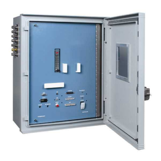
Page 54: Figure 3-2. Microcem Front Panel
January 2002 Flowmeter Printer Connector Connector Connector RS232 Connector Keyboard Connector Mouse Connector Connector Operation Floppy Reset Connector Connector Button Figure 3-2. MicroCEM Front Panel Rosemount Analytical Inc. Model MicroCEM Power Switch A Division of Emerson Process Management Heartbeat Trouble... -
Page 55: Main Display
Note: Exit is only be available when current user has administrative access. Figure 3-3. MicroCEM Pocket PC Display (Main Display Shown) STATUS Indicates that maintenance mode is active. Calibration in process Invalid Reading. Indicates that the reading is invalid due to calibration failure or sensor failure. -
Page 56: Microcem Menu
January 2002 MicroCEM Menu Clicking on the Tools text in the lower left corner of the display activates the MicroCEM menu. From this menu, all of the MicroCEM user-interface func- tions can be accessed. On-screen keyboard is available at any time by clicking on the keyboard button. -
Page 57: Alarm Name
Critical Warm-up Time Limit Critical Rosemount Analytical Inc. A Division of Emerson Process Management DESCRIPTION O2 Calibration Failed to meet the maximum Drift requirements CO Calibration Failed to meet the maximum Drift requirements NOx Calibration Failed to meet the maximum Drift require-... -
Page 58: Microcem Login
January 2002 MicroCEM Login The login dialog appears (Figure 3-6) when first requesting the MicroCEM Settings or MicroCEM Admin. If a valid user name and password are entered, the user logging in will have permission to use the MicroCEM Settings and/or... -
Page 59: Figure 3-8. Range Settings
“Permission denied”. When the MicroCEM Settings are invoked from the Tools menu or the MicroCEM Set- tings button, the MicroCEM Settings tabbed dialog is displayed. The Range page (tab) is displayed initially. -
Page 60: Auto Calibration
Auto Calibration Time and Fre- quency The Auto-Calibration Time and Fre- quency tab allows specifying time and frequency of the auto-calibration. Time field requires military time format. Figure 3-10. Auto Calibration Time and Frequency Rosemount Analytical Inc. A Division of Emerson Process Management... -
Page 61: Manual Calibration
Manual Calibration A dry-run Calibration may be initiated from the Manual Calibration page of the MicroCEM Settings. The results of the calibration will not be applied and only provide a dry run of the calibration. If desired a partial calibration may be in- voked for one or more of the emission types. -
Page 62: Limits
748467-A January 2002 Limits The emission limits alarms can be set on the Limits page of the MicroCEM Settings. When a measured emission exceeds its limit, the emission will have a limit-exceeded status. This is indi- cated on the main display and on the Data-Logs display. -
Page 63: Maintenance Mode
January 2002 Maintenance Mode Maintenance mode may be selected for any of the emission types on the Main- tenance Mode page of the MicroCEM Settings. Choosing maintenance mode will in- voke an “M” flag” onto the data. Cus- tomer can perform routine maintenance while in this setting Figure 3-15. -
Page 64: Microcem Factory Settings
3-4 MicroCEM FACTORY SETTINGS A MicroCEM Factory Settings program is available for use by MicroCEM technicians to set parameters in the MicroCEM or a qualified customer technician. Enter the Factory Settings password at the login dia- log to enter the Factory Settings. This... -
Page 65: Table 3-3. Factory Settings - Calibration
Purge2 Default auto-calibration Purge 2 value in seconds. Rosemount Analytical Inc. A Division of Emerson Process Management If the drift exceeds the allowed amount a drift alarm will occur, and the readings on the channel will no longer be valid until a successful calibration is com- pleted. -
Page 66: Table 3-4. Factory Settings - General
This sets the NOx low limit, below which a limit alarm will occur. This sets the NOx ppm high limit, above which a limit alarm will occur. NOXSensorHighLimit This setting is used to record the MicroCEM Serial Number. CCEM Serial Number Percent O2 used in Diluent correction. -
Page 67: Pid Control Loop Factory Settings
PMT Heater PMT Photo Diode Cooler Table 3-5. PID Settings – Section Names Rosemount Analytical Inc. A Division of Emerson Process Management Zone heater/cooler, Converter Heater, PMT Heater, and PMT Photo Diode Cooler. Table 3-5 shows the section names in the INI file used for each temperature control loop. -
Page 68: Table 3-6. Pid Settings - Sections Descriptions
This is the temperature setpoint, in degrees Celsius, for this tem- perature control loop. If the temperature (°C) is below this value during the MicroCEM process (not including the warm-up phase) an alarm will occur. If the temperature (°C) is above this value during the MicroCEM process (not including the warm-up phase) an alarm will occur. -
Page 69: Microcem Administration
Model MicroCEM 3-5 MicroCEM ADMINISTRATION The MicroCEM Administration dialog is only available to users with MicroCEM Admini- stration permission. If a user is not cur- rently logged in, the login dialog will be displayed. If the current user doesn’t have... -
Page 70: Microcem Data Logs
Instruction Manual 748467-A January 2002 3-6 MicroCEM DATA LOGS The MicroCEM maintains a minimum of 3 months of history in three types of data log files. The first type of log file is the meas- urement log, which contains emission... -
Page 71: Calibration Log File Format
Measured ppm NOx for span phase of calibration NOx Expected span Measured ppm NOx for span phase of calibration NOx Span Drift Rosemount Analytical Inc. A Division of Emerson Process Management Table 3-8. Calibration Log File Format Instruction Manual 748467-A January 2002 fields of the file, in order of occurrence. -
Page 72: Table 3-9. Alarm Log File Format
Table 3-9. Alarm Log File Format Rosemount Analytical Inc. Model MicroCEM Example 3-7-2001 10:24:57 CO Calibration Failed A Division of Emerson Process Management... -
Page 73: View Data Logs
1 Hour 12 Hours 24 Hours Rosemount Analytical Inc. A Division of Emerson Process Management croCEM web pages (see Figure 3-18 and Figure 3-19). This page can be used to view the Emissions log. Other pages may be selected to view the calibration log and the alarm log. -
Page 74: Figure 3-19. View Data Logs Table
Alarms and Calibration data may also be viewed. A Date is shown for 1 min or 15 minute averages. A date range is shown for 1 hour or greater averages. A Division of Emerson Process Management... -
Page 75: Viewing Microcem Data With A Web Browser
Model MicroCEM 3-8 VIEWING MicroCEM DATA WITH A WEB BROWSER The log files may be accessed using a web browser that has access to the MicroCEM over a Wireless LAN, serial port connection (PPP) or Dialup Connection (RAS). The MicroCEM has Window CE Web Server in- stalled and provides a Web-based interface to select and download the Data-Log files. -
Page 76: Emissions Page
The Emissions Page can be used to view emission history in a tabular web- page format. This page is used as part of the MicroCEM User interface as well as by a remote user (probably from a desktop computer). The Emission Data-Logs table is dis-... -
Page 77: Figure 3-23. Calibration Table
Instruction Manual 748467-A Model MicroCEM January 2002 Figure 3-23. Calibration Table Rosemount Analytical Inc. A Division of Emerson Process Management Operation 3-25... -
Page 78: Download Page
Instruction Manual 748467-A January 2002 Download Page The download page of the MicroCEM allows the selection and download of the three types of Data-Logs. To quickly download recent data, a “Download Most Recent Emissions Data” selection is provided. For more control over the date range, a “Down-... -
Page 79: Viewing Microcem Data With Ms Excel
Model MicroCEM 3-9 VIEWING MicroCEM DATA WITH MS EX- The MicroCEM Data may be view with MS Excel using two different methods. The first method is to open the data log files that have been down- loaded onto a workstation. The files may then be opened directly with Excel. -
Page 80: Figure 3-26. Auto Calibration
Operation plays the current emission values and the status of the calibration. The calibration may be canceled before it completes by pressing the Cancel button. Figure 3-26. Auto Calibration Rosemount Analytical Inc. Model MicroCEM A Division of Emerson Process Management... -
Page 81: Section 4 Software
The MicroCEM User Interface Software com- municates with the MicroCEM Control Soft- ware using TCP/IP. It may run locally on the MicroCEM computer or remotely on a Pocket PC with a RS232 connection to the MicroCEM uCEM User Interface Serial... -
Page 82: Software Development Management
Instruction Manual 748467-A January 2002 4-4 SOFTWARE DEVELOPMENT MANAGEMENT Microsoft Visual SourceSafe is used for ver- sion control of all of the MicroCEM software. Compuware’s Track Record is used for change request management and defect tracking. Software Model MicroCEM Rosemount Analytical Inc. -
Page 83: Section 5 Maintenance And Service
Rosemount Analytical Inc. A Division of Emerson Process Management SECTION 5 5-1 OVERVIEW The MicroCEM Analyzer Module requires very little maintenance during normal operation. Occasionally, the detector's reaction chamber and sapphire window may require cleaning, refer to Section 5-5. -
Page 84: Figure 5-1. Microcem Component Location
Assembly Paramagnetic Detector 3-Way Valve Transistor Personality Modules (Figure 5-3) Maintenance and Service Converter (Figure 5-2) Figure 5-1. MicroCEM Component Location Rosemount Analytical Inc. Model MicroCEM NDIR Detector Ozone Generator Thermoelectric Cooler Power Relay Regulator Chemiluminescense Detector (Figure 5-4) Power Supply Assembly... -
Page 85: Figure 5-2. Converter Assembly
Sensor Glass Cloth Rosemount Analytical Inc. A Division of Emerson Process Management and remove the converter. Reassemble in re- verse order, ensuring that the converter is ori- ented with the glass cloth at the bottom and the sensor is oriented correctly inside the heater jacket. -
Page 86: Figure 5-3. Personality Modules And Backplane
You will have to loosen each screw before you can remove the personality mod- ule. Tag each cable and its location before dis- connecting any wiring. This helps in re- assembly. EXIO NDIR Rosemount Analytical Inc. A Division of Emerson Process Management... -
Page 87: Chemiluminescense Detector Assembly
Hold the Reaction Chamber in place while rotating the housing upright. Replace the hold-down screws. Rosemount Analytical Inc. A Division of Emerson Process Management Instruction Manual NOTE Component Positioning. The proce- dure described above is for the pur-... -
Page 88: Figure 5-4. Chemiluminescense Detector Assembly
Chamber (upper section). Replace the top cap and its screws. To reinstall in the Analyzer Module, re- verse the procedure for removal as indi- cated above. Sapphire Window Reaction Chamber Thermistor Assembly Photodiode Socket Assembly Detector Mounting Bracket A Division of Emerson Process Management... -
Page 89: Figure 5-5. Chemiluminescense Detector Assembly – Exploded View
(between Lower Cover and Mounting Bracket) Photodiode Case Ground Heater/Thermostat Assembly 655235. Figure 5-5. Chemiluminescense Detector Assembly – Exploded View Rosemount Analytical Inc. A Division of Emerson Process Management Detector Header Heater Thermostat Tubing Cover O-Ring 876478 Lower Cover Photodiode Assembly (see detail below) M3X0.5 x 20mm Screw (2) - Page 90 Instruction Manual 748467-A Model MicroCEM January 2002 Maintenance and Service Rosemount Analytical Inc. A Division of Emerson Process Management...
-
Page 91: Section 6 Troubleshooting
SECTION 6 TROUBLESHOOTING 6-2 POCKET PC CONNECTION FAILURE In the event the connection between the Pocket PC and the MicroCEM fails, a connection failure dialog will be displayed. It will display the fol- lowing message: Connection with uCEM lost, retrying…... - Page 92 Instruction Manual 748467-A Model MicroCEM January 2002 Troubleshooting Rosemount Analytical Inc. A Division of Emerson Process Management...
-
Page 93: Section 7 Replacement Parts
Photodiode Detector 90003311 Paramagnetic Detector 902124 Flowmeter 905778 4-Port Manifold 905779 2-Way Valve 905780 3-Way Valve 905871 Relay, Power 15A Rosemount Analytical Inc. A Division of Emerson Process Management SECTION 7 REPLACEMENT PARTS Instruction Manual 748467-A January 2002 Replacement Parts... - Page 94 Instruction Manual 748467-A Model MicroCEM January 2002 Replacement Parts Rosemount Analytical Inc. A Division of Emerson Process Management...
-
Page 95: Section 8 Return Of Material
Rosemount Analytical Inc. Process Analytic Division Customer Service Center 1-800-433-6076 Rosemount Analytical Inc. A Division of Emerson Process Management SECTION 8 RETURN OF MATERIAL If warranty service is expected, the defective unit will be carefully inspected and tested at the factory. If the failure was due to the condi-... - Page 96 Instruction Manual 748467-A Model MicroCEM January 2002 Return of Material Rosemount Analytical Inc. A Division of Emerson Process Management...
-
Page 97: Warranty
WARRANTY Goods and part(s) (excluding consumables) manufactured by Seller are warranted to be free from defects in workmanship and material under normal use and service for a period of twelve (12) months from the date of shipment by Seller. Consumables, glass electrodes, membranes, liquid junctions, electrolyte, o-rings, etc., are warranted to be free from defects in workmanship and material under normal use and service for a period of ninety (90) days from date of shipment by Seller. - Page 98 Instruction Manual 748467-A January 2002 Emerson Process Management Rosemount Analytical Inc. Process Analytic Division 1201 N. Main St. Orrville, OH 44667-0901 T (330) 682-9010 F (330) 684-4434 E-mail: gas.csc@emersonprocess.com ASIA - PACIFIC EUROPE, MIDDLE EAST, AND AFRICA Fisher-Rosemount Fisher-Rosemount Ltd.
Need help?
Do you have a question about the MicroCEM and is the answer not in the manual?
Questions and answers