
Related Manuals for Hanna Instruments pH 500 Series


Summary of Contents for Hanna Instruments pH 500 Series
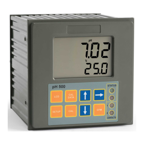
- Page 1 pH 500 & mV 600 Series Panel-mounted, Microprocessor-based pH and ORP Controllers Instruction Manual...
-
Page 2: Table Of Contents
Dear Customer, TABLE OF CONTENTS Thank you for choosing a HANNA product. This instruction manual refers to the following products: PRELIMINARY EXAMINATION ....4 pH controller with single setpoint, ON/OFF pH 500111- GENERAL DESCRIPTION. -
Page 3: Preliminary Examination
• Temperature compensation of the pH reading (for pH 500 PRELIMINARY EXAMINATION Series only). Remove the instrument from the packing material and exam- • Manual temperature setting when the temperature probe is ine it carefully to make sure that no damage has occurred not inserted or temperature exceeds the upper range. -
Page 4: Functional Description
REAR PANEL FUNCTIONAL DESCRIPTION FRONT PANEL 1. RS232 Connection Port (pH500XY2 and mV600XY2 models only) 2. Analog Output (pH500XY1 and mV600XY1 models only) 3. Power Supply Input 4. Alarm Terminal 5. Relay 2 - Second Dosing Terminal (pH5002XY models only) 6. -
Page 5: Specifications Ph 500 & Mv 600
SPECIFICATIONS pH 500 & mV 600 INSTALLATION Range 0.00 to 14.00 pH (pH 500 series only) pH 500 and mV 600 ±2000 mV (mV 600 series only) offer a multitude of -9.9 to 120.0 °C possibilities, from Resolution 0.01 pH (pH 500 series only) single and dual set- 1 mV... -
Page 6: Setup Mode
• Power Supply: Connect a 3-wire power cable SETUP MODE to the terminal strip, while paying attention to the correct line (L), earth (PE) and neu- pH 500 and mV 600 offer a multitude of possibilities from tral (N) terminal connections. ON/OFF or proportional dosage to analog recorder output and from alarm to selftest features. - Page 7 • Then confirm the displayed digit with • After confirmation, the selected param- and move to the next one. eter is displayed. The user can scroll through the parameters by pressing CFM. • When the whole password has been In order to directly set another param- inserted, press CFM to confirm it.
- Page 8 Code Valid Values Default Code Valid Values Default 30 Relay 3 high alarm (HA) 0.00 to 14.00 pH 9.00 pH 92 EEPROM selftest 0: off -2000 to 2000 mV 600 mV 1: on HA>LA, HA>S1 or HA>S2 93 Relays and LEDs selftest 0: off 31 Relay 3 low alarm (LA) 0.00 to 14.00 pH...
-
Page 9: Control Mode
then S1>S2, S2–D2>LA, HA>S1+D1; CONTROL MODE If M1 = 4 and M2 = 3 then S2>S1, S1–D1>LA, HA>S2+D2; The control mode is the normal operational mode for these meters. During control mode pH 500 and mV 600 fulfill the where the minimum deviation (D1 or D2) is 0.5 pH (for following main tasks: pH 500) or 25 mV (for mV 600). - Page 10 An upper boundary is imposed for acid/base dosage time when relays are energized continuously, i.e. when relay works in ON/OFF mode or in proportional mode but in the latter case only if the relay is always ON. This parameter can be set through setup procedure.
- Page 11 • ALWAYS OFF if pH > setpoint; In addition to the user-selectable alarm relays, all pH 500 and mV 600 models are equipped with the Fail Safe alarm feature. Low setpoint mode The Fail Safe feature protects the process against critical errors arising from power interruptions, surges and human errors.
-
Page 12: Idle Mode
IDLE MODE ANALOG OUTPUT During idle mode the device performs the same tasks as when All models pH 500XY1 and mV 600XY1 are provided with the it is in control mode except for the relays. The alarm relay is analog output feature. activated (no alarm condition), the acid and base relays are The output is isolated and can be a voltage or a current. -
Page 13: Rs232 Communication And Data Logging
These values can be changed by the user to have the analog RS232 COMMUNICATION AND DATA LOGGING output matches a different pH range, for example, 4 mA = 3.00 pH and 20 mA = 5.00 pH. All models pH 500XY2 and mV 600XY2 are provided with an To change the default values, the setup mode must be en- RS232 port. -
Page 14: Calibration
Note Cables other than HI 920010 may use a different configu- CALIBRATION ration. In these cases, no communication between the meter and the PC is possible. If you are not using the HI 920010 The controller is factory calibrated for mV and temperature cable, contact the nearest Hanna Customer Service Center inputs as well as for the analog outputs. - Page 15 For accurate calibration, use two beakers for each buffer • Remove the protective cap from the solution, the first one for rinsing the electrode, the second pH electrode and immerse it into the one for calibration. By doing this, contamination between selected buffer solution (e.g.
- Page 16 Two-point Calibration Three-point Calibration • Proceed as described above for one-point cali- • Proceed as described above but do bration, using pH 7.01 as the first point, but do not quit calibration by pressing CAL. not quit calibration by pressing CAL at the end. Note The meter will automatically skip the two buffers that were Note...
- Page 17 CALIBRATION WITH MANUAL TEMPERATURE COMPENSATION mV INPUT CALIBRATION • Enter the calibration procedure and press LCD to display The pH/mV controller is factory calibrated for the mV and the temperature on the secondary LCD. temperature inputs. However, the user may also perform a mV calibration.
- Page 18 • When the reading has stabilized at • Use a Checktemp or a calibrated thermometer with a reso- a point near the first calibration lution of 0.1° as a reference thermometer. point, CAL will stop blinking and an • Immerse the temperature probe in intermittent CFM icon will prompt the the beaker with ice and water as near user to confirm the first calibration.
- Page 19 • Immerse the temperature probe in • Press CFM to confirm the selected parameter that will stop the second beaker as near to the blinking on the primary display. The secondary display shows Checktemp as possible and repeat the HI 931002 or multimeter input value as lower limit of the above procedure.
-
Page 20: Last Calibration Data
LAST CALIBRATION DATA OUTPUT CALIBRATION CALIBRATION CALIBRATION TYPE CODE POINT 1 POINT 2 The meter stores the following information about last calibration in the EEPROM: 0-1 mA 0 mA 1 mA • Date 0-20 mA 0 mA 20 mA • Time 4-20 mA 4 mA 20 mA... - Page 21 Note In any moment, by pressing LCD or CAL DATA the meter will • Press again to view the second memorized buffer return to the regular operating display. at the time of last calibration. The secondary display will show "BUF2" to indicate second buffer. •...
-
Page 22: Startup
STARTUP FAULT CONDITIONS AND SELFTEST PROCEDURES At startup the firmware release code scrolls through the LCD; The fault conditions below may be detected by the software: it is possible to escape from code scrolling pressing any key. • EEPROM data error; During the automatic startup the Real Time Clock (RTC) is •... - Page 23 The error detection for dead loops is performed by watchdog The colon is a useful indicator for the correct position of (see below). squares. You can use special setup codes, perform selftest procedures Note A maximum of two keys may be pressed simultaneously to be for LCD, keyboard, EEPROM, relays and LEDs, watchdog.
-
Page 24: Ph Values At Various Temperatures
RELAYS AND LEDS pH VALUES AT VARIOUS TEMPERATURES Relays and LEDs selftests are executed as follows: Temperature has a significant effect on pH. The calibration First all of the relays and LEDs are switched off, then they are buffer solutions are effected by temperature changes to a lesser switched on one at a time for a few seconds and cyclically. -
Page 25: Electrode Conditioning And Maintenance
If the bulb and/or junction are dry, soak the electrode in ELECTRODE CONDITIONING AND MAINTENANCE HI70300 storage solution for at least one hour. For refillable electrodes**: If the refill solution (electrolyte) is more than 2½ cm (1") below the fill hole, add HI 7082 3.5M KCl electrolyte solu- tion for double junction or HI 7071 3.5M KCl+AgCl electrolyte solution for single junction electrodes. - Page 26 For refillable electrodes**: Refill the electrode with fresh electrolyte (HI 7071 for single • No Slope: junction or HI 7082 for double junction electrodes). Allow - Check the electrode for cracks in glass stem or bulb the electrode to stand upright for 1 hour. Follow the Stor- (replace the electrode if cracks are found).
-
Page 27: Taking Redox Measurements
TAKING REDOX MEASUREMENTS Redox measurements allow the quantification of the oxidizing or reducing power of a solution, and are commonly expressed in mV. Oxidation may be defined as the process during which a molecule (or an ion) loses electrons and reduction as the process by which electrons are gained. -
Page 28: Accessories
RECOMMENDED pH ELECTRODES (all electrodes are gel-filled and with ce- ACCESSORIES ramic junction unless otherwise indicated). HI 1090T Screw connector, external PG13.5 thread, double junction, pH CALIBRATION SOLUTIONS glass body, polymer filled HI 7004M pH 4.01 buffer solution, 230 mL bottle HI 7004L pH 4.01 buffer solution, 500 mL bottle HI 7004/L... - Page 29 PLATINUM ORP ELECTRODES HI 3090T Screw connector, external PG13.5 thread, double junction, Pt, glass body, polymer filled HI 3210B/5 BNC connector, 5 m (16.5') cable, double junction, Pt, plas- tic body, PVDF junction, polymer-filled HI 3210T Screw connector, external PG13.5 thread, double junction, Pt, plastic body, cloth junction GOLD ORP ELECTRODES HI 4932B/5...
- Page 30 ORP ELECTRODES OTHER ACCESSORIES ½‘’ thread, double PVDF junction, polymer filled, max operating pressure of 6 bar (87 BL PUMPS Dosing pumps with flow rate from 1.5 to 20 lph psi) HI 98501 ChecktempC Electronic thermometer (range -50.0 to 150.0°C) HI 98502 ChecktempF Electronic thermometer (range -58.0 to 302°F) HI 6050 &...
-
Page 31: Warranty
• PROBES (DO, µS/cm, RH, T, TDS) warranty, you will be notified of the charges incurred. If the • PUMPS instrument is to be returned to Hanna Instruments, first ob- tain a Returned Goods Authorization number from the • REAGENTS Customer Service department and then send it with ship- •... -
Page 32: Ce Declaration Of Conformity
CE DECLARATION OF CONFORMITY HANNA LITERATURE Hanna publishes a wide range of catalogs and handbooks for an equally wide range of applications. The reference lit- erature currently covers areas such as: • Water Treatment • Process • Swimming Pools • Agriculture •... - Page 33 TECHNICAL SERVICE CONTACTS Australia: Tel. (03) 9769.0666 • Fax (03) 9769.0699 China: Tel. (10) 88570068 • Fax (10) 88570060 Egypt: Tel. & Fax (02) 2758.683 Germany: Tel. (07851) 9129-0 • Fax (07851) 9129-99 Greece: Tel. (210) 823.5192 • Fax (210) 884.0210 Indonesia: Tel.
Need help?
Do you have a question about the pH 500 Series and is the answer not in the manual?
Questions and answers