
Subscribe to Our Youtube Channel
Related Manuals for Hanna Instruments pH500 Series


Summary of Contents for Hanna Instruments pH500 Series
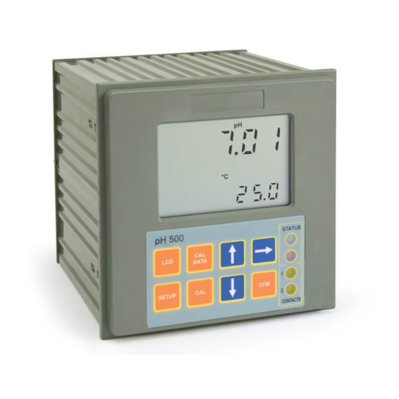
- Page 1 pH500 & mV600 Series Panel-mounted, Microprocessor-based pH and ORP Controllers Instruction Manual...
- Page 2 For technical support, contact your local Hanna Instruments Office or e-mail us at tech@hannainst.com. All rights are reserved. Reproduction in whole or in part is prohibited without the written consent of the copyright owner, Hanna Instruments Inc., Woonsocket, Rhode Island, 02895, USA.
-
Page 3: Table Of Contents
TABLE OF CONTENTS PRELIMINARY EXAMINATION ....4 GENERAL DESCRIPTION ..... . 4 FUNCTIONAL DESCRIPTION . -
Page 4: Preliminary Examination
• LEDs: three (mV600) or four (pH500) LEDs are provided for signaling the energizing of relay 1 (a yellow led), relay 2 (a yellow led in pH500 Series only) and alarm relays (a green and a red LED). • Relays: 1 or 2 output relays for acid or base dosage (COM, NO and NC contacts) and 1 output relay for alarm condition (COM, NO and NC contacts). - Page 5 • Last calibration data internally recorded (non-volatile EE- PROM memory): calibration date and time, pH offset, pH slopes, number of calibration points and correspondent pH values (for pH500 Series only) or calibration date and time and the mV calibration points used (for mV600 Series only).
-
Page 6: Functional Description
2. LCD key exits from setup and calibration modes and reverts back to normal mode (in idle or control phases with the mea- surement on the display). In pH500 series, during pH calibration, alternately displays pH buffer value or current temperature 3. -
Page 7: Mechanical Dimensions
REAR PANEL 1. RS232 Connection Port (pH500XY2 and mV600XY2 models only) 2. Analog Output (pH500XY1 and mV600XY1 models only) 3. Power Supply Input 4. Alarm Terminal 5. Relay 2 - Second Dosing Terminal (pH5002XY models only) 6. Relay 1 - First Dosing Terminal 7. -
Page 8: Specifications Ph500 & Mv600
0.00 -14.00 pH (pH500 series only) Range ±2000 mV (mV600 series only) -9.9 to 120.0 °C 0.01 pH (pH500 series)/ ±1 mV (mV600 series) Resolution 0.1 °C Accuracy ±0.02 pH (pH500 series)/ ±2 mV (mV600 series) (@20 °C/68 °F) ±0.5 °C Typical EMC ±0.2 pH (pH500 series)/ ±10 mV (mV600 series) -
Page 9: Installation
This can cause a rap- id degradation of the electrode. The Hanna Instruments differential input re- duces the likelihood of ground loops. See the diagram for a recommended instal-... - Page 10 • Power Supply: Connect a 3-wire power cable to the terminal strip, while paying attention to the correct line (L), earth (PE) and neutral (N) terminal connections. Power: 115VAC - 100 mA / 230VAC - 50 mA Line Contact: fused inside 400 mA. PE must be connected to ground;...
-
Page 11: Setup Mode
SETUP MODE pH500 and mV600 offer a multitude of possibilities from ON/OFF or proportional dosage to analog recorder output and from alarm to selftest features. The Setup Mode allows the user to set all needed charac- teristics of the meter. The setup mode is entered by pressing SETUP and entering the password when the device is in idle or control mode. - Page 12 • Then confirm the displayed digit with and move to the next one. • When the whole password has been inserted, press CFM to confirm it. Note The default password is set at “0000”. • The LCD will display “SET” on the upper part and “c.00”...
- Page 13 • After confirmation, the selected param- eter is displayed. The user can scroll through the parameters by pressing CFM. In order to directly set another pa- rameter, press SETUP again and en- ter the code or scroll to it by pressing CFM.
- Page 14 Code Valid Values Default 30 Relay 3 high alarm (HA) 0.00 to 14.00 pH 9.00 pH -2000 to 2000 mV 600 mV HA>LA, HA>S1 or HA>S2 31 Relay 3 low alarm (LA) 0.00 to 14.00 pH 5.00 pH -2000 to 2000 mV -600 mV LA<HA, LA<S1 or LA<S2 32 Proportional control mode...
- Page 15 Note The process controller automatically checks to ensure that the entered data matches other related variables. If a wrong configuration is entered, “WRONG” blinks on the LCD to prompt the user. The correct configurations are the following: If M1= / 0 then S1<HA, S1>LA; If M2= / 0 then S2<HA, S2>LA;...
- Page 16 Note The password cannot be viewed when SETUP is pressed without entering the original password first. The default password is set at “0000”. In the event that the user forgets the password, this can be reset to “0000” by pressing and holding CFM and then pressing LCD and CAL DATA at the same time when the pH controller is in normal operating mode (idle or control with measurement displaying).
-
Page 17: Control Mode
CONTROL MODE The control mode is the normal operational mode for these meters. During control mode pH500 and mV600 fulfill the following main tasks: • convert information from pH/ORP and temperature inputs to digital values; • control relays and generate the analog outputs as deter- mined by the setup configuration, display alarm condition;... - Page 18 An upper boundary is imposed for acid/base dosage time when relays are energized continuously, i.e. when relay works in ON/OFF mode or in proportional mode but in the latter case only if the relay is always ON. This parameter can be set through setup procedure.
- Page 19 Setpoint Setpoint + Hysteresis PROPORTIONAL CONTROL MODE The user can vary three different parameters, i.e. the setpoint (S1 or S2), the deviation (D1 or D2) and the proportional control mode period T from 1 to 30 minutes. Duration of the activated control is directly proportional to the error value (Duty Cycle Control Mode): as the measurement approaches setpoint, the ON period diminishes.
- Page 20 • ALWAYS OFF if pH > setpoint; Low setpoint mode 0 alarm Setpoint– Setpoint Deviation Using a similar format, the second relay may be set up according to the diagram below. High setpoint mode Setpoint + Setpoint alarm Deviation ALARM RELAY The alarm relay functions in the following manner: FS•C = NO (Normally Open) Energized Relay...
- Page 21 In addition to the user-selectable alarm relays, all pH500 and mV600 models are equipped with the Fail Safe alarm feature. The Fail Safe feature protects the process against critical errors arising from power interruptions, surges and human errors. This sophisticated yet easy-to-use system resolves these predicaments on two fronts: hardware and software.
-
Page 22: Idle Mode
IDLE MODE During idle mode the device performs the same tasks as when it is in control mode except for the relays. The alarm relay is activated (no alarm condition), the acid and base relays are not activated while the analog output remains activated. -
Page 23: Analog Output
By default the minimum and maximum values of analog output correspond to the minimum and maximum of the range of the meter. For example, for the pH500 series with a selected analog output of 4-20 mA, the default values are 0.00 and 14.00 pH corresponding to 4 and 20 mA,... - Page 24 These values can be changed by the user to have the an- alog output matches a different pH range, for example, 4 mA = 3.00 pH and 20 mA = 5.00 pH. To change the default values, the setup mode must be en- tered.
-
Page 25: Rs232 Communication And Data Logging
After download is complete, use the setup.exe file to install the software. ELECTRICAL CONNECTIONS To connect your Hanna Instruments Office meter to a PC use an HI920010 cable. Make sure that your meter is switched off and plug the con- nectors, one to the meter RS232 connector and the other to the serial port of your PC. - Page 26 Cables other than HI920010 may use a different configu- ration. In these cases, no communication between the meter and the PC is possible. If you are not using the HI920010 cable, contact the nearest Hanna Instruments Customer Service Center or proceed as follows for a proper electrical connection:...
-
Page 27: Calibration
(one-point calibration), but it is always good practice to calibrate in at least 2 points. pH CALIBRATION (for pH500 Series only) The pH controller can be calibrated through a one-point, two-point or three-point calibration. You do not need to enter... - Page 28 For accurate calibration, use two beakers for each buffer solution, the first one for rinsing the electrode, the second one for calibration. By doing this, contamination between the buffers is minimized. RINSE CALIBRATION HI7007 HI7007 To obtain accurate readings, use pH7.01 and pH4.01 if you measure acidic samples, or pH7.01 and pH10.01 for alkaline measurements or perform a 3-point calibration for the entire range.
- Page 29 • Remove the protective cap from the pH electrode and immerse it into the selected buffer solution (e.g. pH7.01) with the Potential Matching Pin and temperature probe, then stir gently. Note The electrode should be submerged ap- proximately 4 cm (1½”) in the solution. The temperature probe should be located as close as possible to the pH electrode.
- Page 30 Two-point Calibration • Proceed as described above for one-point cali- bration, using pH 7.01 as the first point, but do not quit calibration by pressing CAL at the end. Note The meter will automatically skip the buffer that was used for the first calibration to prevent errors.
- Page 31 Three-point Calibration • Proceed as described above but do not quit calibration by pressing CAL. Note The meter will automatically skip the two buffers that were used to prevent errors. • After the second calibration point is confirmed, immerse the pH electrode and the Potential Matching Pin into the third buffer solution (e.g.
- Page 32 CALIBRATION WITH MANUAL TEMPERATURE COMPENSATION • Enter the calibration procedure and press LCD to display the temperature on the secondary LCD. • Unplug any temperature probe that may be attached to the meter. The “°C” symbol will flash. • Note the temperature of the buffer solutions with a Check- tempC or an accurate thermometer with a resolution of 0.1 °C.
- Page 33 mV INPUT CALIBRATION The pH/mV controller is factory calibrated for the mV and temperature inputs. However, the user may also perform a mV calibration. • Short the Connection for Potential Matching Pin (#9 at page7) and the Connection for the Electrode Reference (#8 at page 7) with a jumper wire.
- Page 34 • When the reading has stabilized at a point near the first calibration point, CAL will stop blinking and an inter- mittent CFM icon will prompt the user to confirm the first calibration. • If the display stabilizes at a value significantly different from the first setpoint, an intermittent WRONG icon will prompt the user to check and...
- Page 35 • Use a Checktemp or a calibrated thermometer with a resolution of 0.1 ° as a reference thermometer. • Immerse the temperature probe in the beaker with ice and water as near to the Checktemp as possible. • Press and hold first CFM and then 0 °...
- Page 36 • Immerse the temperature probe in the second beaker as near to the Checktemp as possible and repeat the above procedure. 50 ºC (122 ºF) Calibration procedure may be interrupted by pressing CAL again at any time. If the calibration procedure is stopped this way, or if the controller is switched off before the last step, no calibration data is stored in non-volatile memory (EEPROM).
- Page 37 • Press CFM to confirm the selected parameter that will stop blinking on the primary display. The secondary display shows the HI931002 or multimeter input value as lower limit of the interval. • Use the or to make the HI931002 or multimeter output correspond with the meter’s value shown on the secondary display (e.g.
- Page 38 Note When adjusting values using the or it is important to allow for sufficient response time (up to 30 seconds) The table below lists the values of output codes along with the calibration point values (which are the analog output minimum and the analog output maximum) as indicated on the display.
-
Page 39: Last Calibration Data
LAST CALIBRATION DATA The meter stores the following information about last cali- bration in the EEPROM: • Date • Time • Offset in mV (for pH500 only) • Up to two slopes (for pH500 only) • Up to three buffers While displaying this data, the pH controller remains in control mode. - Page 40 Note In any moment, by pressing LCD or CAL DATA the meter will return to the regular operating display. • Press or to view the time of last calibration. The secondary display will show "HOU" to indicate hours. •...
- Page 41 • Press or again to view the second memorized buffer at the time of last calibration. The secondary display will show "BUF2" to indicate second buffer. • Press or again to view the third memorized buffer at the time of last calibration.
-
Page 42: Startup
STARTUP At startup the firmware release code scrolls through the LCD; it is possible to escape from code scrolling pressing any key. During the automatic startup the Real Time Clock (RTC) is checked to see if a reset occurred since last software initial- ization. -
Page 43: Fault Conditions And Selftest Procedures
FAULT CONDITIONS AND SELFTEST PROCEDURES The fault conditions below may be detected by the software: • EEPROM data error; • I2C internal bus failure; • code dead loop. EEPROM data error can be detected through EEPROM test procedure at startup or when explicitly requested using setup menu. - Page 44 The error detection for dead loops is performed by watchdog (see below). You can use special setup codes, perform selftest procedures for LCD, keyboard, EEPROM, relays and LEDs, watchdog. The operation of these functions is outlined in the setup section. The selftest procedures are described in detail in the following subsections.
- Page 45 The colon is a useful indicator for the correct position of squares. Note A maximum of two keys may be pressed simultaneously to be properly recognized. To exit the keyboard test procedure press LCD, CAL and SETUP simultaneously. EEPROM SELFTEST The EEPROM selftest procedure involves verifying the stored EEPROM checksum.
- Page 46 RELAYS AND LEDS Relays and LEDs selftests are executed as follows: First all of the relays and LEDs are switched off, then they are switched on one at a time for a few seconds and cyclically. User can interrupt the otherwise endless cycle, as indicated by the scrolling message, by pressing a key.
-
Page 47: Ph Values At Various Temperatures
pH VALUES AT VARIOUS TEMPERATURES Temperature has a significant effect on pH. The calibration buffer solutions are effected by temperature changes to a lesser degree than normal solutions. For manual temperature calibration please refer to the following chart: TEMP. pH VALUES ˚C ˚F 4.01... -
Page 48: Electrode Conditioning And Maintenance
ELECTRODE CONDITIONING AND MAINTENANCE * Only available with refillable electrodes. For industrial applications, gel-filled electrodes are preferable due to lesser maintenance requirements. PREPARATION Remove the protective cap. DO NOT BE ALARMED IF ANY SALT DEPOSITS ARE PRES- ENT. This is normal with electrodes and they will disappear when rinsed with water. - Page 49 If the bulb and/or junction are dry, soak the electrode in HI70300 storage solution for at least one hour. For refillable electrodes**: If the refill solution (electrolyte) is more than 2½ cm (1”) be- low the fill hole, add HI7082 3.5M KCl electrolyte solution for double junction or HI7071 3.5M KCl+AgCl electrolyte solution for single junction electrodes.
- Page 50 Inorganic Soak in Hanna Instruments HI7074 inorganic cleaning solution for 15 minutes. Oil/grease Rinse with Hanna Instruments HI7077 Oil & Fat cleaning solution. IMPORTANT After performing any of the cleaning procedures rinse the electrode thoroughly with distilled water, drain and refill the...
- Page 51 • No Slope: - Check the electrode for cracks in glass stem or bulb (replace the electrode if cracks are found). - Make sure cable and connections are not damaged nor lying in a pool of water or solution. • Slow Response/Excessive Drift: soak the tip in HI7061 solution for 30 minutes, rinse thoroughly in distilled water and then follow the Cleaning Procedure above.
-
Page 52: Taking Redox Measurements
TAKING REDOX MEASUREMENTS Redox measurements allow the quantification of the oxi- dizing or reducing power of a solution, and are commonly expressed in mV. Oxidation may be defined as the process during which a molecule (or an ion) loses electrons and reduction as the process by which electrons are gained. - Page 53 Reducing pretreatment: immerse the electrode for a few minutes in HI7091. Oxidizing pretreatment: immerse the electrode for a few minutes in HI7092. If the pretreatment is not performed, the electrode will take significantly longer to respond. As with pH electrodes, gel-filled redox electrodes are more suitable for industrial applications due to lesser maintenance requirements.
-
Page 54: Accessories
ACCESSORIES pH CALIBRATION SOLUTIONS HI7004M pH4.01 buffer solution, 230 mL bottle HI7004L pH4.01 buffer solution, 500 mL bottle HI7004/L pH4.01 buffer solution, 1 L bottle HI7007M pH7.01 buffer solution, 230 mL bottle HI7007L pH7.01 buffer solution, 500 mL bottle HI7007/L pH7.01 buffer solution, 1 L bottle HI7010M pH10.01 buffer solution, 230 mL bottle... - Page 55 RECOMMENDED pH ELECTRODES (all electrodes are gel-filled and with ceramic junction unless otherwise indicated). HI1090T Screw connector, external PG13.5 thread, double junction, glass body, polymer filled HI1210T Screw connector, external PG13.5 thread, double junction, HI1211T plastic body; cloth junction (HI1210T); PVDF junction, polymer-filled (HI1211T) HI2910B/5 BNC connector, 5 m (16.5’) cable, double junction, plastic...
- Page 56 PLATINUM ORP ELECTRODES HI3090T Screw connector, external PG13.5 thread, double junction, Pt, glass body, polymer filled HI3210T Screw connector, external PG13.5 thread, double junction, Pt, plastic body, cloth junction HI3211T Screw connector, external PG13.5 thread, double junction, Pt, plastic body, PVDF junction, polymer-filled HI2930B/5 BNC connector, 5 m (16.5’) cable, double junction, Pt, plastic body with built-in amplifier and external thread, cloth...
- Page 57 HI3210B/5 BNC connector, 5 m (16.5’) cable, double junction, Pt, plastic body, PVDF junction, polymer-filled GOLD ORP ELECTRODES HI4932B/5 BNC connector, 5 m (16.5’) cable, double junction, Au, plastic body with built-in amplifier and external thread ELECTRODES FOR HIGH PRESSURE APPLICATIONS pH ELECTRODES ½‘’...
- Page 58 ORP ELECTRODES ½‘’ thread, double PVDF junction, polymer filled, max operating pressure of 6 bar (87 psi) PLATINUM ELECTRODES Part Code Matching Pin Amplifier Connector Cable HI2002/3 3 m (10’) HI2002/5 5 m (16.5’) HI2003/3 BNC* 3 m (10’) HI2003/5 BNC* 5 m (16.5’) HI2004/5...
- Page 59 OTHER ACCESSORIES BL PUMPS Dosing pumps with flow rate from 1.5 to 20 lph HI98501 ChecktempC Electronic thermometer (range -50.0 to 150.0 °C) HI98502 ChecktempF Electronic thermometer (range -58.0 to 302 °F) HI6050 & HI6051 Submersible electrode holders HI6054 & HI6057 Electrode holders for in-line applications HI778P Screened coaxial cable with screw connectors...
-
Page 60: Warranty
Damage due to accident, misuse, tampering or lack of prescribed maintenance are not covered. If service is required, contact your local Hanna Instruments Office. If under warranty, report the model number, date of purchase, serial number and the nature of the failure. If the repair is not covered by the warranty, you will be notified of the charges incurred. - Page 61 SOFTWARE • THERMOMETERS • TITRATORS • TRANSMITTERS • TURBIDITY METERS • Wide Range of Accessories Most Hanna Instruments meters are available in the following formats: • BENCH-TOP METERS • POCKET-SIZED METERS • PORTABLE METERS • PRINTING/LOGGING METERS • PROCESS METERS (Panel and Wall-mounted) •...
-
Page 62: Ce Declaration Of Conformity
CERTIFICATION All Hanna Instruments conform to the CE European Di- rectives. Disposal of Electrical & Electronic Equipment. The prod- uct should not be treated as household waste. Instead hand it over to the appropriate collection point for the recycling of electrical and electronic equipment which will conserve natural resources. - Page 63 RECOMMENDATIONS FOR USERS Before using this product, make sure it is entirely suitable for your specific application and for the environment in which it is used. Any variation introduced by the user to the supplied equipment may degrade the controller’s performance. For yours and the controller’s safety do not use or store the controller in hazardous environments.
- Page 64 World Headquarters Hanna Instruments Inc. Highland Industrial Park 584 Park East Drive Woonsocket, RI 02895 USA www.hannainst.com...
Need help?
Do you have a question about the pH500 Series and is the answer not in the manual?
Questions and answers