
Related Manuals for Hanna Instruments mV 602 Series


Summary of Contents for Hanna Instruments mV 602 Series
- Page 1 pH 502 & mV 602 Series Panel-mounted, Microprocessor-based pH and ORP Controllers Instruction Manual...
-
Page 2: Table Of Contents
WARRANTY ......69 CE DECLARATION OF CONFORMITY ... 70 © 1999 Hanna Instruments All rights are reserved. Reproduction in whole or in part is prohibited without the written... -
Page 3: Preliminary Examination
• Calibration: for pH 502 series at 1, 2 or 3 points with pH PRELIMINARY EXAMINATION 4.01, 7.01 and 10.01buffers; for mV 602 series at 1 or 2 points at 0, 350 and 1900 mV. Remove the instrument from the packing material and exam- ine it carefully to make sure that no damage has occurred •... -
Page 4: Functional Description
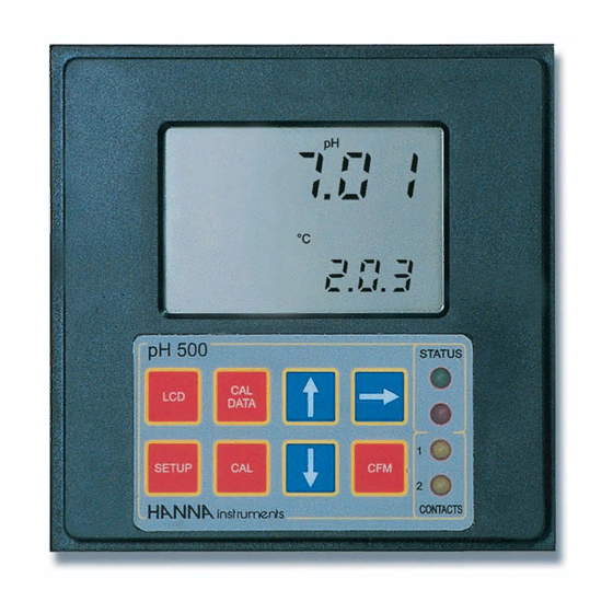
REAR PANEL FUNCTIONAL DESCRIPTION Models with 2-contact Models with 3-contact electromechanical output relay(s) solid state output relay(s) FRONT PANEL 1. 6-pin RS485 terminal (not for pH502XY1 and mV602XY1) 2. Analog output (not for pH502XY2 and mV602XY2) 3. Power supply input 1. -
Page 5: Specifications Ph 502 & Mv 602
SPECIFICATIONS pH 502 & mV 602 INSTALLATION Range 0.00-14.00 pH (pH 502 series only) pH 502 and mV 602 ±2000 mV (mV 602 series only) offer a multitude of -9.9 to 120.0 °C possibilities, from single Resolution 0.01 pH (pH 502 series) / 1 mV (mV 602 series) and dual setpoints to 0.1 °C ON/OFF or PID dos-... -
Page 6: Setup Mode
• Power Supply: Connect a 3-wire power cable SETUP MODE to the terminal strip, while paying attention to the correct line (L), earth (PE) and neu- pH 502 and mV 602 offer a multitude of possibilities from tral (N) terminal connections. ON/OFF or PID dosage to analog recorder output and from alarm to selftest features. - Page 7 • Then confirm the displayed digit with • After confirmation, the selected param- and move to the next one. eter is displayed. The user can scroll through the parameters by pressing CFM. • When the whole password has been In order to directly set another param- inserted, press CFM to confirm it.
- Page 8 Code Valid Values Default Code Valid Values Default 60 Current day 01 to 31 from RTC 22* Relay 2 setpoint (S2) 0.00 to 14.00 pH 6.00 pH -2000 to 2000 mV -500 mV 61 Current month 01 to 12 from RTC 23* Relay 2 hysteresis (H2) 0.00 to 14.00 pH 1 pH...
-
Page 9: Control Mode
If M1 = 3 and M2 = 2 CONTROL MODE then S1>S2+H2, S2>LA, HA>S1+D1; If M1 = 2 and M2 = 3 The control mode is the normal operational mode for these then S1+H1<S2, S1>LA, HA>S2+D2; meters. During control mode pH 502 and mV 602 fulfill the If M1 = 4 and M2 = 1 following main tasks: then S1<S2–H2, S1–D1>LA, HA>S2;... - Page 10 An upper boundary is imposed for acid/base dosage time when relays are energized continuously, i.e. when relay works in ON/OFF mode or in PID mode but in the latter case only if the relay is always ON. This parameter can be set through setup procedure.
- Page 11 An example of how the response overshoot can be improved with In pH502 and mV602 the proportional action is set directly a proper rate action setting is depicted in the following graphic. as “Deviation” in pH and mV units respectively. Relation be- tween Deviation (D) and PB is: D = Range * PB/100 Each setpoint has a selectable proportional band: PB1 for...
- Page 12 1. Starting from a solution with a pH or mV value different ALARM RELAY from the dosed liquid (at least a 3 pH or 150mV difference) The alarm relay functions in the following manner: turn on the dosing device at its maximum capacity without FS•C = NO (Normally Open) the controller in the loop (open loop process).
-
Page 13: Idle Mode
This is an important feature since with most meters the alarm IDLE MODE terminals close only when an abnormal situation arises, how- ever, due to line interruption, no alarm During idle mode the device performs the same tasks as is sounded, causing extensive damage. when it is in control mode except for the relays. -
Page 14: Analog Output
To change the default values, the setup mode must be en- ANALOG OUTPUT tered. Setup codes for changing the analog output minimum and maximum are 41 or 42, respectively. For the exact All models pH 502XY1,pH 502XY3, mV 602XY1 and mV procedure, refer to the setup mode section in the manual. -
Page 15: Rs 485 Communication
HI 92500 Windows ® compatible application soft- ware offered by Hanna Instruments. The user-friendly HI 92500 offers a variety of features such as logging selected variables or plotting the recorded data. It There is an internal short between the two A pins and be- also has an on-line help feature to support you throughout tween the two B pins. - Page 16 As additional feature, the controller is also Command Parameter Description provided with two pins (5V and 0V) in or- der to apply the Fail Safe Open Line null Request calibration data protection method. To avoid erroneous Request setup item NN readings in Open-Line conditions, pull- up and pull-down resistors should be K 01...
- Page 17 Note Note If the controller is not in control or idle mode and the tem- The controller answers to the GET command with the same perature reading is requested through the TMR command, data format explained in the SET command. the controller answers with the last acquired reading when it was in control or idle mode.
-
Page 18: Calibration
If asking for last calibration data and the controller was never CALIBRATION calibrated, it answers with “0”; e.g. “01<STX>0<ETX>”. If the controller was calibrated, it answers with “1” followed The controller is factory calibrated for mV and temperature by the calibration data. The Data field of the answer has the inputs as well as for the analog outputs. - Page 19 For accurate calibration, use two beakers for each buffer • Remove the protective cap from the solution, the first one for rinsing the electrode, the second pH electrode and immerse it into the one for calibration. By doing this, contamination between selected buffer solution (e.g.
- Page 20 Two-point Calibration Three-point Calibration • Proceed as described above for one-point cali- • Proceed as described above but do bration, using pH 7.01 as the first point, but do not quit calibration by pressing CAL. not quit calibration by pressing CAL at the end. Note The meter will automatically skip the two buffers that were Note...
- Page 21 CALIBRATION WITH MANUAL TEMPERATURE COMPENSATION PH BUFFER SELECTION • Enter the calibration procedure and press LCD to display A one point pH calibration at a value different from standard the temperature on the secondary LCD. buffer is possible by directly entering the desired calibration value.
- Page 22 OFFSET AND SLOPE DIRECT SELECTION mV INPUT CALIBRATION Whenever the pH electrode offset and slope parameters are The pH/mV controller is factory calibrated for the mV and known, it is possible to directly calibrate the meter entering temperature inputs. However, the user may also perform a the electrode parameters.
- Page 23 • When the reading has stabilized at • Use a Checktemp or a calibrated thermometer with a reso- a point near the first calibration lution of 0.1° as a reference thermometer. point, CAL will stop blinking and an • Immerse the temperature probe in intermittent CFM icon will prompt the the beaker with ice and water as near user to confirm the first calibration.
- Page 24 • Immerse the temperature probe in • Press CFM to confirm the parameter that stops blinking on the second beaker as near to the the primary display.The secondary display shows the multi- Checktemp as possible and repeat meter or HI931002 input value as the interval lower limit. the above procedure.
-
Page 25: Last Calibration Data
Note In any moment, by pressing LCD or CAL DATA the meter will LAST CALIBRATION DATA return to the regular operating display. The meter stores the following information about last calibration in the EEPROM: • Date • Time • Press to view the time of last calibration. -
Page 26: Startup
• Press again to view the second memorized buffer STARTUP at the time of last calibration. The secondary display will show "BUF2" to indicate second buffer. At startup the firmware release code scrolls through the LCD; it is possible to escape from code scrolling pressing any key. During the automatic startup the Real Time Clock (RTC) is checked to see if a reset occurred since last software ini- tialization. -
Page 27: Fault Conditions And Selftest Procedures
The error detection for dead loops is performed by watchdog FAULT CONDITIONS AND SELFTEST PROCEDURES (see below). The fault conditions below may be detected by the software: You can use special setup codes, perform selftest procedures for LCD, keyboard, EEPROM, relays and LEDs, watchdog. •... - Page 28 The colon is a useful indicator for the correct position of RELAYS AND LEDS squares. Relays and LEDs selftests are executed as follows: Note A maximum of two keys may be pressed simultaneously to be First all of the relays and LEDs are switched off, then they are properly recognized.
-
Page 29: Ph Values At Various Temperatures
pH VALUES AT VARIOUS TEMPERATURES ELECTRODE CONDITIONING AND MAINTENANCE Temperature has a significant effect on pH. The calibration buffer solutions are effected by temperature changes to a lesser degree than normal solutions. For manual temperature calibration please refer to the fol- lowing chart: TEMP pH VALUES... - Page 30 If the bulb and/or junction are dry, soak the electrode in For refillable electrodes**: Refill the electrode with fresh electrolyte (HI 7071 for single HI70300 storage solution for at least one hour. junction or HI 7082 for double junction electrodes). Allow the electrode to stand upright for 1 hour.
-
Page 31: Taking Redox Measurements
• No Slope: TAKING REDOX MEASUREMENTS - Check the electrode for cracks in glass stem or bulb Redox measurements allow the quantification of the oxidizing (replace the electrode if cracks are found). or reducing power of a solution, and are commonly expressed - Make sure cable and connections are not damaged nor in mV. -
Page 32: Accessories
ACCESSORIES pH CALIBRATION SOLUTIONS HI 7004M pH 4.01 buffer solution, 230 mL bottle HI 7004L pH 4.01 buffer solution, 500 mL bottle HI 7004/L pH 4.01 buffer solution, 1 L bottle HI 7007M pH 7.01 buffer solution, 230 mL bottle Reducing pretreatment: immerse the electrode for a few min- HI 7007L pH 7.01 buffer solution, 500 mL bottle... - Page 33 RECOMMENDED pH ELECTRODES (all electrodes are gel-filled and with ce- PLATINUM ORP ELECTRODES ramic junction unless otherwise indicated). HI 3090T Screw connector, external PG13.5 thread, double junction, HI 1090T Screw connector, external PG13.5 thread, double junction, Pt, glass body, polymer filled glass body, polymer filled HI 3210T Screw connector, external PG13.5 thread, double junction,...
- Page 34 ORP ELECTRODES ½‘’ thread, double PVDF junction, polymer filled, max operating pressure of 6 bar (87 psi) HI 3210B/5 BNC connector, 5 m (16.5') cable, double junction, Pt, plas- tic body, PVDF junction, polymer-filled PLATINUM ELECTRODES Part Code Matching Pin Amplifier Connector Cable GOLD ORP ELECTRODES...
-
Page 35: Warranty
If the repair is not covered by the HI 8615L ORP transmitter with LCD warranty, you will be notified of the charges incurred. If the instrument is to be returned to Hanna Instruments, first ob- HI 92500 Windows ®... -
Page 36: Ce Declaration Of Conformity
CE DECLARATION OF CONFORMITY HANNA LITERATURE Hanna publishes a wide range of catalogs and handbooks for an equally wide range of applications. The reference lit- erature currently covers areas such as: • Water Treatment • Process • Swimming Pools • Agriculture •... - Page 37 TECHNICAL SERVICE CONTACTS Australia: Tel. (03) 9769.0666 • Fax (03) 9769.0699 China: Tel. (10) 88570068 • Fax (10) 88570060 Egypt: Tel. & Fax (02) 2758.683 Germany: Tel. (07851) 9129-0 • Fax (07851) 9129-99 Greece: Tel. (210) 823.5192 • Fax (210) 884.0210 Indonesia: Tel.
Need help?
Do you have a question about the mV 602 Series and is the answer not in the manual?
Questions and answers