
Related Manuals for Hanna Instruments Pool Line BL131


Summary of Contents for Hanna Instruments Pool Line BL131
- Page 1 INSTRUCTION MANUAL Swimming Pool Controllers BL131 BL132 with Cloud Connectivity Hanna Instruments Inc., 584 Park East Drive, Woonsocket, RI 02895 USA www.hannainst.com...
-
Page 2: Table Of Contents
Recommendations for Users .........70 Warranty ...............70 All rights are reserved. Reproduction in whole or in part is prohibited without the copyright owner's written consent, Hanna Instruments Inc., Woonsocket, Rhode Island, 02895, USA. Hanna Instruments reserves the right to modify the design, construction, or appearance of its products without advance notice. -
Page 3: Preliminary Examination
1. PRELIMINARY EXAMINATION Remove the instrument and accessories from the packaging and examine it carefully. For further assistance, please contact your local ® Hanna Instruments office or email us at tech@hannainst.com. BL13X swimming pool controllers are available in two installation configurations: •... -
Page 4: Specifications
4 Specifications 3. SPECIFICATIONS 3.1. FEATURE COMPARISON TABLE Acid Chlorine Analog Hanna Cloud measurement measurement dosing pump dosing pump outputs connectivity BL131 – BL132 – 3.2. TECHNICAL SPECIFICATIONS Range 0.00 to 14.00 pH* Resolution 0.01 pH Accuracy... - Page 5 Specifications Simplified pool startup procedure • Ensures 12 hour dosing to reach a target setpoint Pool startup mode • Enabled or disabled manually from the controller menu • Disabled automatically when setpoint is reached or 12 hour timeout has expired •...
- Page 6 6 Specifications Additional Specifications Meter password protection • Password protected setup, calibration, and log recall USB-C port • Data export to USB flash drive • Software update pH and ORP Alarm system • Intuitive alert system based on LED color coded alarm system •...
-
Page 7: Hi1036-18Xx Probe Specifications
Specifications 3.3. HI1036-18XX* PROBE SPECIFICATIONS Range 0.00 to 12.00 pH ±2000 mV Temperature 0.0 to 70.0 °C (32.0 to 158.0 °F) Reference Ag / AgCl reference electrode (3.5M KCl) Junction Cloth Matching pin Body PVDF Top thread 3/4" NPT Connector DIN connector Maximum pressure @25 °C 3 bar (43.5 psi) Probe ordering codes... -
Page 8: Description
4. DESCRIPTION 4.1. GENERAL DESCRIPTION & INTENDED USE ® The Hanna Instruments BL13X swimming pool controllers are automatic systems, specially designed to measure and control pH and free-chlorine levels. The modular design of the system supports integration with larger, external pumps for pH and free-chlorine level control of larger pools. - Page 9 Description Main features • Pool startup mode • Freeze prevention mode • Magnetic faceplate removal stops internal pumps movement • Front-facing wiring panel for easy accessibility • Two internal peristaltic dosing pumps with automatic Proportional pump control • Manual control for pump priming •...
-
Page 10: Functional & Display Description
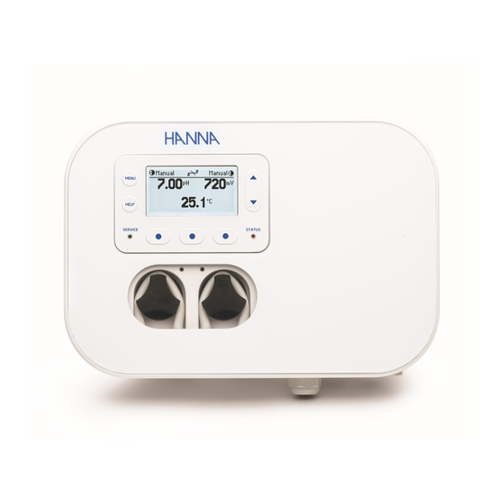
10 Description 4.2. FUNCTIONAL & DISPLAY DESCRIPTION Front Panel • Magnetic faceplate encases a custom display and keypad with tactile feedback. • Two LEDs indicate controller alarm ( ) ) conditions. A red LED (S ) indicates fault condition. STATUS ... - Page 11 Description BL132 front view – faceplate removed Side view SWIMMING POOL CONTROLLER MENU Air Temp HOLD USB-C HELP ACID/BASE LEVELS Cl LEVEL COMM SERVICE STATUS USE COPPER OR ALUMINUM CONDUCTORS ONLY Power ACID/BASE RECIRCULATION PUMP PUMP PUMP ALARM NO C NO C NO C NC NO C NC...
- Page 12 12 Description Keypad description 1. Menu key 2. Help key MENU 3. Service LED Air Temp 4. Liquid Crystal Display (LCD) HOLD USB-C HELP ACID/BASE LEVELS 5. Navigation keys Cl LEVEL COMM 6. Functional keys SERVICE STATUS USE COPPER OR ALUMINUM CONDUCTORS ONLY 7.
-
Page 13: Wiring
Description 4.3. WIRING 1. Remove the magnetic faceplate (A) to access the electrical connectors cover (B). 2. Use a screwdriver to remove the single screw (C) attaching the panel cover. Note: See exposed low‑voltage electrical connectors. 3. Use a screwdriver to remove the single screw attaching the high-voltage electrical connectors cover (D). -
Page 14: Cable Wiring
14 Description 4.4. CABLE WIRING BL131 front view – exposed electrical connectors Air Temp HOLD ACID/BASE LEVELS Cl LEVEL COMM USE COPPER OR ALUMINIUM CONDUCTORS ONLY pH Cl 1. Pump tubing gland seals 3. Cable gland (analog output) 2. Probe DIN connector 4. - Page 15 Description BL132 front view – exposed electrical connectors Air Temp HOLD ACID/BASE LEVELS Cl LEVEL COMM USE COPPER OR ALUMINIUM CONDUCTORS ONLY pH Cl 3. Cable gland (Ethernet wiring) 1. Pump tubing gland seals 2. Probe DIN connector 4. Cable gland (power, digital input, alarm relay) Do not run power cabling through the same opening as other cables.
- Page 16 16 Description Low-Voltage Electrical Connectors Warning! Always disconnect the pool controller from power when making electrical connections. BL131 exposed low-voltage connectors BL132 exposed low-voltage connectors MENU Air Temp Air Temp HOLD HOLD USB-C HELP ACID/BASE LEVELS ACID/BASE LEVELS Cl LEVEL Cl LEVEL COMM COMM...
- Page 17 Description Pumps and Alarms Connectors Warning! Always disconnect the pool controller from power when adjusting electrical connections. BL131 exposed connectors BL132 exposed connectors MENU Air Temp Air Temp HOLD HOLD USB-C HELP ACID/BASE LEVELS ACID/BASE LEVELS Cl LEVEL Cl LEVEL COMM COMM STATUS...
-
Page 18: Installation
18 Installation 5. INSTALLATION Two installation configurations: • In-line ƒ The probe is placed in the saddle, mounted in pipe after the pool filter. • Panel mounted flow cell ƒ The probe is mounted in the flow cell, close to the controller. ƒ... - Page 19 PUMP PUMP PUMP ALARM prior to cover removal. NO C Refer servicing to quali ed service personnel. BL132 WARNING Hanna Instruments www.hannainst.com Made in Romania pH Cl Probe: HI1036-18XX 2A T 2A T 2A T 2A T DISCONNECT POWER SUPPLY Electrical PRIOR TO COVER REMOVAL.
- Page 20 PUMP PUMP PUMP ALARM prior to cover removal. NO C Refer servicing to quali ed BL132 service personnel. WARNING Hanna Instruments www.hannainst.com Made in Romania pH Cl Probe: HI1036-18XX 2A T 2A T 2A T 2A T DISCONNECT POWER SUPPLY Electrical PRIOR TO COVER REMOVAL.
-
Page 21: Mounting Recommendations For Saddle
Installation 5.3. MOUNTING RECOMMENDATIONS FOR SADDLE • Select required drill size. See table below for dimension details. Drill Pipe • Place the upper part of the saddle (5) on top of the pipe (3) with the seal (4) placed over the hole. •... -
Page 22: Connecting The Probe To The Pump Controller
22 Installation 5.4. CONNECTING THE PROBE TO THE PUMP CONTROLLER Ensure the probe is connected and calibrated before installation. 1. Remove protective cap and verify the O-ring is in place. 2. Insert the nut onto the probe. O-ring Nut adapter Protective cap 3. -
Page 23: Installing The Aspiration Filter
Installation 5.5. INSTALLING THE ASPIRATION FILTER The aspiration filter is used in the reagent tank to filter and prevent debris from entering the tubing. • Cut the required length of aspiration tubing (flexible) to reach between peristaltic pump inlet and aspiration filter. •... -
Page 24: Flow Cell Installation
24 Installation 5.7. FLOW CELL INSTALLATION In a flow cell configuration the water flows from the inlet valve to the flow cell and returns in the line via the outlet valve. PART A Preparing the inlet and outlet valve assemblies •... - Page 25 Installation PART C Connecting the probe to the controller • Remove the protective cap and verify the O-ring (2) is in place. • Insert the nut (5) into the probe. Carefully screw the adapter (4) into the probe, paying attention not to damage the O-ring. •...
-
Page 26: Bl132 Cloud Connectivity
• Click on Create Account and fill in the email and password information. • Read the Hanna Instruments Privacy Policy and click Create Account. A validation email will be sent to the registered email. Follow the link to access your account. Confirm the user account before logging in. - Page 27 Installation Remote update using Hanna Cloud (primary user) ® We aim to constantly improve our products and offer professional enhanced product features. As such, Hanna Instruments periodically releases firmware updates. 1. Go to www.hannacloud.com 2. Log into your account. 3. Locate the device on the dashboard.
- Page 28 28 Installation USB Firmware Update Requirements • Firmware update package file • USB 2.0 or 3.2 flash drive Procedure 1. Copy the firmware update package file to the root directory of a USB-C drive. 2. Power off the meter. 3. Plug in the USB-C drive. 4.
-
Page 29: Setup
Setup 6. SETUP 6.1. USER INTERFACE The pool controller menu is grouped into following categories: • Acid (Base) Pump (R) control: OFF/AUTO, ON 10s • Chlorine (Cl ) Pump (R) control: OFF/AUTO, ON 10s • pH Options: CAL, Setup, GLP •... -
Page 30: General Setup Overview
Setup BL13X Log Recall Overview LOG RECALL MODE 6.2. GENERAL SETUP OVERVIEW Menu Items Diagram Select parameter Adjust parameter Setup Modify Date Format yyyy-mm-dd Key Beep Alarms and Errors Beep Decimal • LCD Contrast 50 % LCD Backlight 50 % Language English... - Page 31 Setup Configurable Options General Settings Range / Options Default Description / Menu Navigation • With item selected, press Modify for options drop-down list. 30 sec. Log Interval 1 min.; 5 min.; 15 min.; 30 sec. • Press keys to navigate options. 30 min.;...
- Page 32 Setup General Settings Range / Options Default Description / Menu Navigation With item selected, press View to display model version, model Controller Info number, language version, and serial number. With item selected, press View to display model version, language Probe Info version, and serial number.
-
Page 33: Parameters Setup Overview
Setup Hold Input submenu when option is enabled in General Settings The Hold Input submenu is used to configure what should happen when the Hold Input is triggered. • If Enabled, the Alarm will trigger when the Hold is triggered. •... - Page 34 Setup pH Configurable Options pH Settings Range / Options Default Description / Menu Navigation Dosing Type Base / Acid Acid • With item selected, press the toggle switch to configure option. The BL meter regulates the pH to the pH value set in this parameter. •...
- Page 35 Setup pH Settings Range / Options Default Description / Menu Navigation The check mark confirms option as enabled. If enabled, warnings and errors will be flagging during operation. A warning is an event generated when erroneous conditions Enable appear; and when measured values or parameter values are Warnings and Errors Disabled Disable...
- Page 36 Setup ORP Configurable Options ORP Settings Range / Options Default Description / Menu Navigation The BL meter will regulate the Chlorine (Cl ) pump operation to get mV value set in this parameter. • With item selected, press Set to modify. Set Point 200 to 900 mV / 1 mV 700 mV...
- Page 37 Setup ORP Settings Range / Options Default Description / Menu Navigation If enabled, warnings and errors will be flagging during operation. A warning is an event generated when erroneous conditions appear; and when measured values or parameter values are outside the expected range. Enable ...
- Page 38 Setup Temperature Configurable Options Temp. Settings Range / Options Default Description / Menu Navigation The High Alarm Value for temperature is the minimum temperature value that will trigger an alarm status and stop the control pumps. Mask time will delay alarm activation.* (Low+0.1) to 100.0 °C / 0.1 °C 50.0 °C Alarm High Value...
- Page 39 Setup Temp. Settings Range / Options Default Description / Menu Navigation Analog Outputs are used as part of the pool control system. Disabled indicates that analog output has not been allocated Analog Output Disabled Disabled to any function. (BL131) AO1, AO2, AO3 AO1, AO2, AO3 assign an analog output to a temperature reading.
- Page 40 Setup Air-temperature Configurable Options Air-Temp. Settings Range / Options Default Description / Menu Navigation • With item selected, press the toggle switch to enable or Enable Air-T Enabled disable air-temperature (Air-T) readings. Disable • The check mark confirms option as enabled. •...
-
Page 41: Bl132 Hanna Cloud Setup
Setup 6.4. BL132 HANNA CLOUD SETUP Status Static Modify Netmask: 255.255.255.0 Gateway: 192.168.1.1 DNS Addr: 192.168.1.1 Hanna Cloud Options These settings are required to permit Hanna Cloud monitoring. IP addressing: an Internet Protocol address (IP address) is a numerical label assigned to each device connected to a network that uses the IP for communication. -
Page 42: Password Protected Settings
Setup 6.5. PASSWORD PROTECTED SETTINGS The password protection feature protects against unauthorized configuration changes on the meter and deleting log files. Once set, a series of functions cannot be subsequently modified. This feature is represented by the lock icon – е – displayed on the functional key or on screen title. •... -
Page 43: Analog Outputs (Bl131)
Setup 6.6. ANALOG OUTPUTS (BL131) The three 4-20 mA isolated current outputs are factory calibrated and can be configured through the Setup menu as pH / ORP or Temperature outputs. • Each output can be configured to a parameter (or disabled) and can be connected to a chart recorder or data logger. •... -
Page 44: Operational Guide
Operational Guide 7. OPERATIONAL GUIDE 7.1. CALIBRATION pH Calibration The pH electrode can be calibrated on the controller using automatic, two-point calibration. The electrode should be (re)calibrated: • Before in-line or flow cell installation • Whenever the pH electrode is replaced •... - Page 45 Operational Guide • Press MENU to return to measurement mode. Delete calibration • Press CLR from calibration screen. Device prompts for confirmation • Press YES to confirm or NO to exit and return to calibration screen. If, during calibration, the temperature sensor detects extreme values, or the sensor broken, a blinking 25.0 °C is displayed (bottom right corner of the screen.
- Page 46 Operational Guide Single-Point pH Calibration Single-point pH calibration can be performed with the probe installed in the saddle and allows users to adjust the measured pH value so that it matches the value determined with a hand held meter, without removing the probe from the saddle. Prior to calibration: •...
- Page 47 Operational Guide ORP Calibration If both pH and ORP calibrations are required, calibrate the pH value first. A pH calibration can give inaccurate readings if the probe was used in ORP standard first. Preparation • Pour small quantities of the ORP standard into clean beakers. •...
-
Page 48: Measurement
Operational Guide 7.2. MEASUREMENT • Start the recirculation pump. • BL13X-20 controllers: verify the flow cell fills correctly. • Set up the pump controller, probe, and required accessories. Controller is now ready. • Turn on the controller. After initialization has been completed, the controller enters measurement screen. •... - Page 49 Operational Guide On-display pump status when in measurement mode, pool startup, and off-season modes BL131 status bar BL132 status bar Description Pumps set on OFF MANUAL MANUAL MANUAL MANUAL Level detection indicates pH and Cl volumes are low TANK TANK System waiting for pH to reach setpoint WAIT pH WAIT pH Alarm status...
-
Page 50: Overview Control Mode
50 Operational Guide 7.3. OVERVIEW CONTROL MODE Control Mode is the normal operational mode. During control, the device: • Measures then converts probe’s signal to a measurement (temperature corrected pH), the ORP voltage, and temperature. • Provides proportional feed with an adjustable band for acid and chlorine additions. •... - Page 51 Operational Guide An overview of pH and ORP proportional control is presented in the graph below. THRESHOLD STATUS SERVICE pH/Chlorine internal pump LED control and pump off Notification LED pH/Chlorine internal pump LED control and pump running Note: if remote pumps are used the icon is displayed flashing.
- Page 52 52 Operational Guide Manual or Auto Pump Control for pH / Chlorine Control • Select the OFF option to set the (each) pump to MANUAL. • When On 10s is selected, the pump runs continuously for 10 seconds. • Press Add 10s button to increase the time up to 90 seconds. Remaining time is displayed next to the selected pump in the menu or next to the pump on the top bar of the measurement screen.
-
Page 53: Logging
Logging 8. LOGGING The controller logging system supports periodic and automatic save mode for all parameters as well as an events logging system. The log file stores a maximum of 100 events. Data is stored as per configured time interval. Once the 100 event limit is reached, the oldest logged event is deleted. - Page 54 54 Logging Export Logged Data 1. Press Options from Log Recall screen. Users have the option to export a selected log file or all logs. 2. Insert the USB-C flash drive. 3. Press CFM to continue (ESC returns users to a previous screen). "Transfer in progress"...
-
Page 55: Event Log
Recalled events display event index (title bar) and logging date along with time. EVENTS OVERVIEW Type Definition ® (Fatal) Errors An error is a critical event that requires Hanna Instruments technical support. An alarm is an event generated when programmed alarm conditions have been met. Configurable triggers: • External Hold Alarms •... - Page 56 (12V power supply out of range) ERROR _ DI _ POWER 0x00800 Digital input power failure. Errors ® When encountered, restart the controller. If the error persists, contact Hanna Instruments technical support. Error Description ERROR _ EEP _ CTRL _ CHECKSUM Incorrect EEPROM checksum.
- Page 57 Logging Alarm Description ALARM _ LOW _ ORP Measured ORP has dropped below Alarm Low value. ALARM _ OVER _ RANGE _ ORP Measured ORP exceeds probe specification range. ALARM _ UNDER _ RANGE _ ORP Measured ORP has dropped below probe specification range. ALARM _ LOW _ LEVEL _ ACID _ TANK pH tank level is too low.
- Page 58 58 Logging Setup Codes BL13X operates an event logging system whereby when setting new parameter values, a Setup event and event code are generated. Log event stores the event code and both new and old values. Event Code Setup Parameter Event Code Setup Parameter Key beep Hold Input Contact...
-
Page 59: Event Management
Event Management 9. EVENT MANAGEMENT BL13X controllers have an intuitive and user-friendly events-management system that allows for quick event source identification. There are four event types filtered using controller Setup options. Press HELP key from measurement screen to view all active events. EVENT TYPE: WARNING Triggered by... - Page 60 Event Management EVENT TYPE: ERROR Triggered during process control and affects pH and /or ORP control A condition is evaluated only if it’s enabled. See noted exceptions. Note: “No probe”, “Hold input active”, and “Remote Hold “ are not dependent on “Warnings and Errors ” settings. Errors are logged and viewed in Log Recall.
- Page 61 Event Management EVENT TYPE: SYSTEM ERROR Triggered by critical events, place the controller in ERROR mode. Events are continuously monitored. When in ERROR mode, the device: • Stops the dosing pumps • Stops logging • Activates the alarm relay (relay not energized) •...
- Page 62 Event Management LED NOTIFICATIONS ON CONTROLLER STATUS LED notifications LED type Description Solidly illuminated Flashes not present system running, no events not present system requires user attention STATUS not present technical assistance required not present service required SERVICE &...
- Page 63 Event Management Dosing pump status with associated LED signal STATUS SERVICE Alarm & Errors Events pH pump pump LED Cl pump pump LED Auto-Off Auto-Off High/Low Alarm Auto-Off Auto-Off Temperature Auto-Off Auto-Off pH outside specifications range Auto-Off Auto-Off...
-
Page 64: Maintenance
Maintenance 10. MAINTENANCE 10.1. ELECTRODE CONDITIONING & MAINTENANCE Preparation • Remove the electrode protective cap. • Rinse any salt deposits with water. • Shake down the probe to eliminate any air bubbles trapped inside the glass bulb. • If the bulb and/or junction are dry, soak the electrode in HI70300 Storage solution for at least one hour. - Page 65 Maintenance 5. Place the tubing on the left side of the pump and start to manually rotate the pump rotor to the right until the tubing is on the pump. 6. Fix the plastic holder in its place on the right and left side. 7.
-
Page 66: Accessories
66 Accessories 11. ACCESSORIES Probes HI1036-18XX BL130-900 Industrial pH / ORP / Ambient Temperature Probe for Temperature / Matching Pin BL131, BL132 combined probes 1 m (3.3') cable = attached cable length 02, 05, 10, 15, 20 (m) PROBE TEMP DIGITAL ALARM INPUTS... - Page 67 Accessories Flow Cell Saddle and Fittings BL120-410 Flow cell for BL130-411 BL131, BL132, and Flow cell panel spare part BL120, BL121, BL122, BL123 × × BL120-150 Saddle kit for Ø 50 mm pipe BL120-450 contains: Flow cell kit for Ø 50 mm pipe •...
- Page 68 68 Accessories BL120-275 BL120-575 Injector saddle for Ø 75 mm Probe saddle for Ø 75 mm pipe, pipe, 1/2" thread 1 - 1/4" thread BL120-501 BL120-400 Protective saddle cap, Flow cell probe adapter kit 1 - 1/4" thread BL120-401 BL120-402 Flow cell valve Flow cell tubing, (10 m) BL120-602...
-
Page 69: Abbreviations
Abbreviations Electrode Storage Solutions HI70300L Storage solution, 500 mL Buffer Solutions HI70004P pH 4.01 buffer sachets, 20 mL (25 pcs.) HI70007P pH 7.01 buffer sachets, 20 mL (25 pcs.) HI70010P pH 10.01 buffer sachets, 20 mL (25 pcs.) HI7004L pH 4.01 buffer solution, 500 mL HI7007L pH 7.01 buffer solution, 500 mL HI7010L... -
Page 70: Certification
(engraved on the bottom of the meter) and the nature of the problem. If the repair is not covered by the warranty, you will be notified of the charges incurred. If the instrument is to be returned to Hanna Instruments, first obtain a Returned Goods Authorization (RGA) number from the Technical Service department and then send it with shipping costs prepaid.
Need help?
Do you have a question about the Pool Line BL131 and is the answer not in the manual?
Questions and answers