Table of Contents
Advertisement
Quick Links
Advertisement
Table of Contents

Subscribe to Our Youtube Channel
Related Manuals for TYAN YR190-B7018


Summary of Contents for TYAN YR190-B7018
- Page 1 YR190-B7018 Service Engineer’s Manual http://www.tyan.com...
- Page 2 http://www.tyan.com...
- Page 3 Corporation and has been reviewed for accuracy and reliability prior to printing. MiTAC assumes no liability whatsoever, and disclaims any ® express or implied warranty, relating to sale and/or use of TYAN products including liability or warranties relating to fitness for a particular purpose or merchantability.
- Page 4 There will be danger of explosion if battery is incorrectly replaced. Replace only with the same or equivalent type recommended by manufacturer. Dispose of used battery according to manufacturer instructions and in accordance with your local regulations. http://www.tyan.com...
- Page 5 About this Manual This manual provides you with instructions on installing your TYAN YR190-B7018. This Manual is intended for experienced users and integrators with hardware knowledge of personal computers. This manual consists of the following parts: Provides an introduction to the TYAN YR190-B7018...
- Page 6 SAFETY INFORMATION Before installing and using TYAN YR190-B7018, take note of the following precautions: ·Read all instructions carefully. ·Do not place the unit on an unstable surface, cart, or stand. ·Do not block the slots and opening on the unit, which are provided for ventilation.
-
Page 7: Table Of Contents
Table of Contents Chapter 1: Overview ................. 9 About the TYAN YR190-B7018 ..........9 Features.................. 10 Product Model................. 12 Standard Parts List ..............13 1.4.1 Box Contents Per Node ........... 13 1.4.2 Accessories ..............14 About the Product ..............16 1.5.1... - Page 8 3.7.1 SATA Backplane Board Features........54 3.7.2 SATA Backplane Board Connector Pin Definitions ..55 Replacing the Power Supply..........57 Appendix I: Cable Connection Tables .......... 59 Appendix II: FRU Parts Table ............61 Appendix III: Technical Support............ 63 http://www.tyan.com...
-
Page 9: Chapter 1: Overview
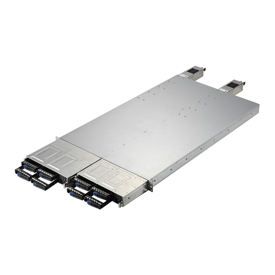
Chapter 1: Overview About the TYAN YR190-B7018 ® Congratulations on your purchase of the TYAN YR190-B7018, a highly optimized rack-mountable barebone system. The YR190-B7018 is ® designed to support Intel Xeon 5500 processors and up to DDR3-800/1066/1333 memory per node, providing a rich feature set and ®... -
Page 10: Features
Features TYAN YR190B7018 (B7018Y190X2-045V4H) 1U Rackmount Frame w/ 2x 1U Blades Form Factor YR190 Chassis Model Dimension (D x W x 28.74" x 17.32" x 1.72" (730 x 440 x 43.6mm) Blade Dimension 28.74" x 8.46" x 1.61" (730 x 214.8 x 40.8mm) - Page 11 3 Channels per CPU Memory channel 1.5V Memory voltage (1) PCI-E Low-Profile Gen.2 x16 slot PCI-E Expansion Slots Pre-install TYAN (per blade) M7018-R16-1L, 1U PCI-E x16 riser card (right) Riser Card Total (3) ports, (1) dedicated for IPMI Port Q'ty LAN (per blade)
-
Page 12: Product Model
(1) YR190-B7018 Barebone Barebone (1) Quick Ref. Guide / (1) MB User's manual + Manual (1) BB User's manual Package (1) TYAN installation CD Contains Installation CD (1) Sliding rail kit for YR190 Rail kit (4) Heatsinks / (4) Power Cords... -
Page 13: Standard Parts List
1.4.1 Box Contents Per Node Component Description 1U chassis, 2 nodes (4) hot swap HDD bays per node ® TYAN S7018 system board (pre-installed) 450W single Power Supply (pre-installed) (1) 40x28mm System Fan (pre-installed) (2) 40x56mm System Fans... -
Page 14: Accessories
If any items are missing or appear damaged, contact your retailer or ® browse to TYAN ’s website for service: http://www.tyan.com ® The web site also provides information of other TYAN products, as well as FAQs, compatibility lists, BIOS settings, etc. ® 1 x TYAN 4 Heatsinks... - Page 15 Rail Kit Rail x 2 Screw Pack http://www.tyan.com...
-
Page 16: About The Product
Activity LED: blinking green Drive present, with activity Fault LED: Off Activity LED: Off HDD Fail Fault LED: Red Activity LED: random Identify Fault LED: blinking red @ 4 Hz Activity LED: random Rebuild Fault LED: blinking red @ 1 Hz http://www.tyan.com... - Page 17 Power up and power down the system (Use a pin) Press once and the blue ID LED on the rear panel 7. ID (UID) will light up. The Power LED on the front panel will turn blue. 8. Reset Press to reset the system http://www.tyan.com...
-
Page 18: System Rear View (Per Node)
Left: slow blinking green 100 Mbps Link Right: green Left: blinking green 100 Mbps Activity Right: green Left: slow blinking green 1000 Mbps Link Right: amber Left: blinking green 1000 Mbps Activity Right: amber Left: Off No Link Right: Off http://www.tyan.com... -
Page 19: Internal View (Per Node)
1.5.3 Internal View (Per Node) Number Description HDD Cage SATA HDD Backplane Board System Fans Power Distribution Board Memory Slots CPU Sockets PCI-E Riser Card Assembly http://www.tyan.com... - Page 20 NOTE http://www.tyan.com...
-
Page 21: Chapter 2: Setting Up
A grounding strap or an anti-static pad Most of the electrical and mechanical connections can be disconnected with your hands. It is recommended that you do not use pliers to remove connectors as it may damage the soft metal or plastic parts of the connectors. http://www.tyan.com... -
Page 22: Precautions
Metallic parts or metal flakes can cause electrical shorts. Note: All connectors are keyed to only attach one way. All use the correct screw size as indicated in the procedures. http://www.tyan.com... -
Page 23: Installing Motherboard Components
Installing Hard Drives The YR190-B7018 supports four 2.5” hard drives per node. Follow these instructions to install a hard drive. Press the locking tabs at both sides to pull the node out. Unscrew to lift up the node cover. http://www.tyan.com... - Page 24 Press the locking lever latch and pull the locking lever open. http://www.tyan.com...
- Page 25 Slide the HDD tray out. Unscrew the HDD tray bracket. Place a hard drive into the drive tray. Use four screws to secure the HDD. http://www.tyan.com...
- Page 26 Reinsert the HDD tray into the chassis. Press the locking lever to secure the tray. Repeat the same procedures to install other HDD trays. http://www.tyan.com...
-
Page 27: Installing The Cpu And Heatsink
Installing the CPU and Heatsink Follow the steps below to install the processor and heatsink. Locate the CPU socket. Pull the CPU lever up to unlock the CPU socket. Open the socket to a full open position. Take off the CPU protection cap. http://www.tyan.com... - Page 28 Place the CPU in the CPU socket. http://www.tyan.com...
- Page 29 Close the socket and press the CPU socket lever down to secure the CPU. Place the heatsink on top of the CPU and secure it with 4 screws. http://www.tyan.com...
-
Page 30: Installing The Memory
Press the memory slot locking levers in the direction of the arrows as shown in the following illustration. Align the memory module with the slot. When inserted properly, the memory slot locking levers lock automatically onto the indentations at the ends of the module. http://www.tyan.com... - Page 31 DIMM B0 x(*) x(*) x(*) x(*) DIMM B1 x(*) x(*) x(*) DIMM A0 x(*) x(*) DIMM A1 x(*) x(*) 1066MHz Max Memory combination Single Rank Unbuffered DIMMs 24GB(12x2GB DIMMs) Dual Rank Unbuffered DIMMs 48GB(12x4GB DIMMs) http://www.tyan.com...
- Page 32 DIMM B1 x(**) x(**) x(**) DIMM A0 x(*) x(**) x(**) DIMM A1 x(**) x(*) 1066MHz x(**) 800MHz Max Memory combination Single Rank Registered DIMMs 48GB(12x4GB DIMMs) Dual Rank Registered DIMMs 96GB(12x8GB DIMMs) Quad Rank Registered DIMMs 96GB(12x8GB DIMMs) http://www.tyan.com...
-
Page 33: Rack Mounting
Installing the Server in a Rack Follow these instructions to mount the TYAN YR190-B7018 into an industry standard 19” rack. NOTE: Before mounting the TYAN YR190-B7018 in a rack, ensure that all internal components have been installed and that the unit has been fully tested. -
Page 34: Installing The Inner Rails To The Chassis
2.2.2 Installing the inner Rails to the Chassis Draw out the inner rails from the rail assembly. Install inner rails to left and right side of chassis. Push the rails forwards to lock the rails in place. http://www.tyan.com... -
Page 35: Installing The Outer Rails To The Rack
(2 sets front / 2 sets rear) for each side. Secure the rails to the rack as shown. Repeat if you want to install more chassis to the rack. Step 2 To make the installation easier, we suggest that you remove all nodes before you insert the chassis to the rack. http://www.tyan.com... -
Page 36: Rack Mounting The Server
2.2.4 Rack mounting the Server To install the chassis to the rack Lift the chassis and then insert the inner slide rails into the outside rails. Push the chassis into the rack. http://www.tyan.com... - Page 37 Screw the chassis to the rack. Insert the node into the chassis. Repeat for the second node. Step 4 To remove the chassis from the rack Remove the nodes. Unscrew the chassis. http://www.tyan.com...
- Page 38 Press the locking tabs on both sides of the chassis to pull the chassis out. Note: To avoid injury, it is strongly recommended that two people lift the TYAN YR190-B7018 into the place while a third person screws it to the rack. http://www.tyan.com...
-
Page 39: Chapter 3: Replacing Pre-Installed Components
Motherboard, front panel board, SATA HDD board, M2087-R PCI-E Riser card, System fans, and Power supply unit etc. Disassembly Flowchart The following flowchart outlines the disassembly procedure. Rear Components Node DIMMs Power CPU/Heatsink Assembly PCI-E Card Mainboard Mainboard http://www.tyan.com... - Page 40 Front Components Node PCBs Front Panel SATA HDD Board Board http://www.tyan.com...
-
Page 41: Replacing Motherboard Components
The YR190-B7018 has one preinstalled M7018_R16-1L riser card, Follow the instructions below to disassemble the M7018-R16-1L and install a new riser card. Locate the riser card assembly in the chassis. Lift the assembly Unscrew the riser card assembly. Remove the PCI-E bracket. http://www.tyan.com... - Page 42 Screw the riser card to the assembly and put it back in place. (optional for M7018-R16-1L) Unscrew to replace a new M7018-R16-1L card. Follow the procedures mentioned earlier in reverse order to place the riser card assembly back into the chassis. http://www.tyan.com...
-
Page 43: Disconnecting All Motherboard Cables
Disconnecting All Motherboard Cables Before replacing the motherboard or certain components, remove cables connected to the motherboard. Follow these instructions to remove all motherboard cables. Disconnect all the power and fan cables. 2. Disconnect SATA cables and front panel cable. http://www.tyan.com... -
Page 44: Removing The Motherboard
After removing all of the aforementioned cables, follow the instructions below to remove the motherboard from the chassis. Remove the heatsink and processor if installed. Remove the nine screws securing the motherboard to the chassis. Carefully lift the motherboard from the chassis. http://www.tyan.com... -
Page 45: Replacing The Power Distribution Board
Replacing the Power Distribution Board Follow these instructions to replace the Power Distribution Board. Disconnect all cables from the power distribution board. Unscrew to take out the power distribution board. Repeat the procedures described earlier to replace a new power distribution board. http://www.tyan.com... -
Page 46: Replacing The Front Panel Board
Replacing the Front Panel Board Follow these instructions to replace the Front Panel board. Release cables from the cable clip. Unscrew the front panel tray. Pull the front panel tray from the chassis. Disconnect cables from the front panel board. http://www.tyan.com... - Page 47 Unscrew to take out the front panel board. 6. Replace a new front panel board and screw it to the front panel tray. 7. Repeat the procedures described earlier in reverse order to place the front panel tray back into place. http://www.tyan.com...
-
Page 48: Front Panel Board Features
1 VCC_USB0 Power connect to 5V (for USB) 6 USB_P1_P USB_P1 + 2 VCC_USB1 Power connect to 5V (for USB) 7 GND Ground 3 USB_P0_N USB_P0 - 8 GND Ground 4 USB_P1_N USB_P1 - 9 NC 5 USB_P0_P USB_P0 + 10 NC http://www.tyan.com... -
Page 49: Replacing The System Fan
Follow these instructions to replace the cooling fans in your system. Locate the cooling fans in your system. Unplug the cables connected to the mainboard and lift the fan unit up from the chassis. Remove the rubber screws from the fan. http://www.tyan.com... - Page 50 Replace a new fan and use the screw driver to push the screw back into the screw hole. Reinstall the fan into the chassis following the procedures described earlier in reverse order. Remove the rubber screws from the fan. After replacing the new fans, reinstall the rubber screws into the fan. http://www.tyan.com...
- Page 51 Reinstall the fans into the chassis following the procedures described earlier in reverse order. Connect the fan cables. http://www.tyan.com...
-
Page 52: Replacing The Sata Backplane Board
Replacing the SATA Backplane Board Disconnect all cables from the backplane board. Unscrew the backplane bracket. Lift the bracket up from the chassis. http://www.tyan.com... - Page 53 Unscrew the backplane board from the bracket. Replace a new SATA Backplane Board and reinstall it into the chassis following the above steps in reverse. http://www.tyan.com...
-
Page 54: Sata Backplane Board Features
3.7.1 SATA Backplane Board Features Front View Rear View Connector Description SATA0~SATA3 SATA Connector J1~J4 HDD Connector Power Connector CPLD Connector SGPIO Connector http://www.tyan.com... -
Page 55: Sata Backplane Board Connector Pin Definitions
HDD Connector: J1/J2/J3/J4 Pin NO Pin name Pin NO Pin name SAS_TX+ SAS_TX- SAS_RX- SAS_RX+ VDD_5_RUN SAS_Present_L P8 VDD_5_RUN VDD_5_RUN HD_PRS_L SAS_LED VDD_12_RUN VDD_12_RUN VDD_12_RUN Power Connector:PW1 Pin No. Net Name Description VDD_12_RUN 12V Power Ground Power Ground VDD_5_RUN 5V http://www.tyan.com... - Page 56 CPLD_JTAG_TDO JTAC_TDO DataOut VDD_3P3_RUN 3.3V CPLD_JTAG_TDI CPLD_JTAG_TMS JTAC_TMS DataOut Ground SGPIO Connector J10 Net Name Description Net Name Description SMBUS_3V3_CLK_CPLD SMBus CLK SAS_GPIO2 SGPIO SLOAD SAS_GPIO0 SGPIO DataIN SMBUS_3V3_DATA_CPLD SMBus Data SAS_GPIO3 SGPIO SCLOCK SAS_GPIO1 SGPIO DataOUT Ground HD_ERR_LED http://www.tyan.com...
-
Page 57: Replacing The Power Supply
Replacing the Power Supply 1. Press and hold the latch to pull the power supply out. 2. After replacing a new power supply, press and hold the latch to push the power supply back into the chassis. http://www.tyan.com... - Page 58 NOTE http://www.tyan.com...
-
Page 59: Appendix I: Cable Connection Tables
→ SATA0 → SATA1 SATA Cable → SATA2 → SATA3 3. B4P PWR and SGPIO Cable SATA/SAS BP Board to Power Distribution Board (PDB) SATA/SAS BP Connect to S7018MB Board → B4P Cable → SGPIO Conn. J21 SGPIO Cable http://www.tyan.com... - Page 60 Front Panel Board (FPB) to S7018 MB Connect to S7018 MB → FP Conn. J23 Control Cable → USB2 Conn. J11 USB Cable Power Supply Cables PDB to S7018 MB Connect to S7018 MB → 2x10P PWR → PSMI Cable COM2 J39 http://www.tyan.com...
-
Page 61: Appendix Ii: Fru Parts Table
Supply FAN;12V,9GV0412P3J071,14700RPM,40X40X CFAN-0380 336252012374 28MM FAN;12V,9CRA0412P5J08,15800RPM,40X40X CFAN-0068 336252012277 56MM Rack Mounting CRAL-0170 340786900010 Slide Rail Kit Part NOTE: The FRU Parts List is subject to change without notice. Please visit our web site at http://www.tyan.com for the latest update. http://www.tyan.com... - Page 62 NOTE http://www.tyan.com...
-
Page 63: Appendix Iii: Technical Support
MiTAC serves multiple market segments with the industry’s most competitive services to support them. TYAN's tech support is some of the most impressive we've seen, with great response time and exceptional organization in general.” — Anandtech.com Please feel free to contact us directly for this service at tech-support@tyan.com... - Page 64 -mber. The RMA number should be prominently displayed on the outside of the shipping carton and the package should be mailed prepaid. TYAN will pay to have the board shipped back to you. ® TYAN YR190-B7018 Service Engineer’s Manual V1.00 Document No.:...
Need help?
Do you have a question about the YR190-B7018 and is the answer not in the manual?
Questions and answers