Table of Contents
Advertisement
Quick Links
Advertisement
Table of Contents

Related Manuals for TYAN YR292-B5538-X4


Summary of Contents for TYAN YR292-B5538-X4
- Page 1 YR292-B5538-X4 Service Engineer’s Manual http://www.tyan.com...
- Page 2 http://www.tyan.com...
- Page 3 MITAC assumes no liability whatsoever, and disclaims any express or implied warranty, relating to sale ® and/or use of TYAN products including liability or warranties relating to fitness for a particular purpose or merchantability. MITAC retains the right to make changes to produce descriptions and/or specifications at any time, without notice.
- Page 4 This Class A digital apparatus complies with Canadian ICES-003. Cet appareil numérique de la Classe A est conforme à la norme NMB-003 du Canada. Notice for Europe (CE Mark) ● This product is in conformity with the Council Directive 2004/108/EC. http://www.tyan.com...
- Page 5 Replace only with the same or equivalent type recommended by manufacturer. Dispose of used battery according to manufacturer instructions and in accordance with your local regulations. VCCI-A ● この装置は、クラスA情報技術装置です。この装置を家庭環境で使用すると電 波妨害を引き起こすことがあります。この場合には使用者が適切な対策を講ず るよう要求されることがあります。 Safety: EN/IEC 60950-1 ● This equipment is compliant with CB/LVD of Safety: EN/IEC 60950-1. http://www.tyan.com...
- Page 6 About this Manual This manual provides you with instructions on installing your TYAN YR292-B5538-X4. This Manual is intended for experienced users and integrators with hardware knowledge of personal computers. This manual consists of the following parts: Chapter 1: Provides an introduction to the TYAN YR292-B5538-X4...
- Page 7 Safety and Compliance Information Before installing and using TYAN YR292-B5538-X4, take note of the following precautions: ·Read all instructions carefully. ·Do not place the unit on an unstable surface, cart, or stand. ·Do not block the slots and opening on the unit, which are provided for ventilation.
- Page 8 To reduce the risk of bodily injury, electric shock, fire and damage to the equipment, observe all precautions included in this guide. You must become familiar with the safety information in this guide before you install, operate, or service TYAN products. Symbols on Equipment Caution. This symbol indicates a potential hazard.
- Page 9 · Make sure racks are coupled together if it is a multiple-rack installation. · Make sure the rack is level and stable before installing an appliance in the rack. · Make sure the leveling jacks are extended to the floor. http://www.tyan.com...
- Page 10 · Plug the power cord into a grounded (earthed) electrical outlet that is easily accessible at all times. · In all European electrical environments, you must ground the Green/Yellow tab on the power cord. If you do not ground the http://www.tyan.com...
- Page 11 TYAN, your authorized TYAN partner, or their agents. Equipment Modifications · Do not make mechanical modifications to the system. TYAN is not responsible for the regulatory compliance of TYAN equipment that has been modified.
- Page 12 – Liquid has been spilled on the product or an object has fallen into the product. – The product has been exposed to rain or water. – The product has been dropped or damaged. – The product does not operate normally when you follow the operating instructions. http://www.tyan.com...
- Page 13 http://www.tyan.com...
-
Page 14: Table Of Contents
Table of Contents Chapter 1: Overview ................. 17 About the TYAN YR292-B5538-X4 ........17 Features .................. 18 Product Model ................. 20 Standard Parts List ..............21 1.4.1 Box Contents Per Node ........... 21 ... - Page 15 Change Smbios Event Log Settings ......130 5.12 Save & Exit Menu ............. 131 Appendix I: Fan and Temp Sensors ..........133 Appendix II: Cable Connection Tables ........... 137 Appendix III: FRU Parts Table ............139 http://www.tyan.com...
- Page 16 Appendix IV: Technical Support ............. 141 http://www.tyan.com...
-
Page 17: Chapter 1: Overview
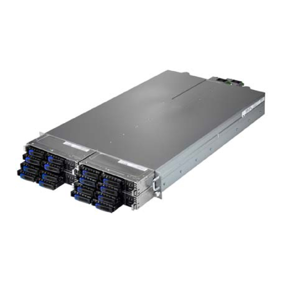
The YR292-B5538-X4 not only empowers your company in nowadays IT demand but also offers a smooth path for future application usage. ® TYAN is also proud to deliver the YR292-B5538-X4 in a version that can support up to sixteen hot-swap hard drives (four HDDs per node). The ®... -
Page 18: Features
Features TYAN YR292B5538 (B5538Y292X4-080PV4HR-BDW) Form Factor 2U Rackmount Gross Weight 29 kg Feature Four nodes in one chassis Chassis Model YR292 Dimension (D x W x System 28.74" x 17.32" x 3.44" (730 x 440 x 87.5mm) Blade Dimension (D 28.74"... - Page 19 Class A VCCI Class A CB/LVD Operating Temp. 10° C ~ 35° C (50° F~ 95° F) Non-operating Operating - 40° C ~ 70° C (-40° F ~ 158° F) Temp. Environment In/Non-operating 90%, non-condensing at 35° C Humidity http://www.tyan.com...
-
Page 20: Product Model
RoHS RoHS 6/6 Compliant Yes Barebone (1) YR292-B5538 Barebone Package Contains Manual (1) Quick Installation Guide Installation CD (1) TYAN installation CD Product Model Model HDD Bays Power supply YR292-B5538-X4 Hot-swap, 16 HDDs 1+1 Redundancy 800 Watts (four nodes) http://www.tyan.com... -
Page 21: Standard Parts List
Standard Parts List This section describes the YR292-B5538-X4 package contents and accessories. Open the box carefully and ensure that all components are present and undamaged. The product should arrive packaged as illustrated below. 1.4.1 Box Contents Per Node Component Description... -
Page 22: Accessories
If any items are missing or appear damaged, contact your retailer or browse to ® TYAN ’s website for service: http://www.tyan.com ® The web site also provides information of other TYAN products, as well as FAQs, compatibility lists, BIOS settings, etc. ® TYAN Motherboard... -
Page 23: About The Product
Green Blinking LAN1 Link Green Solid On Active Green Blinking LAN2 Link Green Solid On HDD Ready Green Solid On (integrated) HDD Access Green Blinking NOTE: If an external HBA card is installed, the HDD LED will not function. http://www.tyan.com... - Page 24 The jumper settings are as follows: Master Node setting Master Jumper Setting Node Node 1 JP6 (1,2), JP7 (1,2) Node 2 JP6 (3,4), JP7 (3,4) Node 3 JP8 (1,2), JP9 (1,2) Node 4 JP8 (3,4), JP9 (3,4) http://www.tyan.com...
- Page 25 Activity LED Status LED Color: Green Color: Red No driver present or power disconnected No Activity Solid ON Access Activity Blinking Driver Present HDD Fail Don’t care Solid ON Identifying Don’t care Blinking @1Hz Rebuilding Don’t care Blinking @4Hz http://www.tyan.com...
-
Page 26: System Rear View (Per Node)
LAN LED: The three onboard Ethernet ports have green and amber LEDs to indicate LAN status. The table below illustrates the different LED states. http://www.tyan.com... - Page 27 Green Amber 1000Mb linked RJ-45 Green 100Mb linked Linkage(Right) 10Mb mode or No LAN Disabled linked NOTE: “Left” and “Right” are viewed from the rear panel. ID LED State Color Description Blue System identified ID LED System not identified http://www.tyan.com...
-
Page 28: Internal View (Per Node)
1.5.3 Internal View (Per Node) Number Description HDD Cage SATA HDD Backplane Board System Fans Power Distribution Board CPU Socket Memory PCI-E Riser Card Assembly http://www.tyan.com... -
Page 29: Chapter 2: Setting Up
Caution! To avoid damaging the motherboard and associated components, do not use torque force greater than 7kgf/cm (6.09 lb/in) on each mounting screw for motherboard installation. Do not apply power to the board if it has been damaged. http://www.tyan.com... -
Page 30: Precautions
Working on a system that is connected to a power supply can be extremely dangerous. Follow the guidelines below to avoid damage to YR292-B5538-X4 or injury to yourself. Ground yourself properly before removing the top cover of the system. -
Page 31: Installing Motherboard Components
CPUs, memory modules, HDD and add on cards. 2.1.1 Installing Hard Drives The YR292-B5538-X4 supports (4) 2.5” hard drives per node. Follow these instructions to install a hard drive. Warning!!! Always install the hard disk drive to the chassis after the chassis is secured on the rack. - Page 32 Slide the HDD tray out. Unscrew the HDD tray bracket. Place a hard drive into the drive tray. Use four screws to secure the HDD. http://www.tyan.com...
- Page 33 Reinsert the HDD tray into the chassis. Press the locking lever to secure the tray. Repeat the same procedures to install other HDD trays. http://www.tyan.com...
-
Page 34: Installing The Cpu And Heatsink
2.1.2 Installing the CPU and Heatsink Follow the steps below to install the processor and heatsink. Take off the CPU Socket protection cap. Pull the CPU lever up to unlock the CPU socket. http://www.tyan.com... - Page 35 Open the socket to a fully open position. Place the CPU in the CPU socket. Make sure the gold arrow is located in the right direction. Close the socket and press the CPU socket lever down to secure the CPU. http://www.tyan.com...
- Page 36 Place the heatsink on top of the CPU and secure it with 4 screws. http://www.tyan.com...
-
Page 37: Installing The Memory
Press the memory slot locking levers in the direction of the arrows as shown in the following illustration. Align the memory module with the slot. When inserted properly, the memory slot locking levers lock automatically onto the indentations at the ends of the module. http://www.tyan.com... - Page 38 Quantity of memory √ √ installed √ √ √ √ √ √ √ √ √ √ √ √ √ http://www.tyan.com...
- Page 39 (4x 4GB DIMMs) UDIMM (4x 1GB DIMMs) 16GB 32GB Dual Rank 8GB (4x 4GB DIMMs) (4x 8GB DIMMs) UDIMMs (4x 2GB DIMMs) NOTE: 1. Support DIMM type:Unbuffered DDR3 ECC 2. No support for RDIMMs and SODIMM DIMM Slots Per Ranks per DIMM DIMM Speed Support Voltage Channel 1DPC 1333/1600 1.5V Single Rank UDIMM 2DPC 1333/1600 1.5V 1DPC 1333/1600 1.5V Dual Rank UDIMMs 2DPC 1333/1600 1.5V NOTE: 1. CPU has no HW or FW voltage restrictions, but only the “Supported Voltage” is POR and validated for each configuration. http://www.tyan.com...
-
Page 40: Rack Mounting
Follow these instructions to mount the TYAN YR292-B5538-X4 into an industry standard 19” rack. NOTE: Before mounting the TYAN YR292-B5538-X4 in a rack, ensure that all internal components have been installed and that the unit has been fully tested. Screw Kit List... -
Page 41: Installing The Inner Rails To The Chassis
2.2.2 Installing the inner Rails to the Chassis Draw out the inner rails from the rail assembly. Install inner rails to the left and right side of chassis. Push the rails forwards to lock the rails in place. http://www.tyan.com... -
Page 42: Installing The Outer Rails To The Rack
/ 2 sets rear) for each side. Secure the rails to the rack as shown. Repeat Step 2 if you want to install more chassis to the rack. To make the installation easier, we suggest that you remove all nodes before you insert the chassis to the rack. http://www.tyan.com... -
Page 43: Rack Mounting The Server
2.2.4 Rack mounting the Server To install the chassis to the rack Lift the chassis and then insert the inner slide rails into the outside rails. Push the chassis back into the rack. http://www.tyan.com... - Page 44 Screw the chassis to the rack. http://www.tyan.com...
- Page 45 Press the locking tabs on both sides of the chassis to pull the chassis out. NOTE: To avoid injury, it is strongly recommended that two people lift the TYAN YR292-B5538-X4 into the place while a third person screws it to the rack. http://www.tyan.com...
- Page 46 NOTE http://www.tyan.com...
-
Page 47: Chapter 3: Replacing Pre-Installed Components
Motherboard, front panel board, SATA HDD board, M2087-R PCI-E Riser card, System fans, and Power supply unit etc. Disassembly Flowchart The following flowchart outlines the disassembly procedure. Rear Components Node Cover DIMMs Power CPU/Heatsink Assembly PCI-E Card Mainboard Mainboard http://www.tyan.com... - Page 48 (25 C). If the maintenance work lasts longer than 5 minutes or the room temperature is higher than 25 C, please unplug the AC cord first in order to assure the power system is not in no load operation. http://www.tyan.com...
-
Page 49: Replacing Motherboard Components
Follow Chapter 2.1.1 to pull the node out. 3.3.1 Replacing Expansion Card The YR292-B5538-X4 has one preinstalled M7018_R16-1L riser card, Follow the instructions below to disassemble the M7018-R16-1L and install a new riser card. Unscrew the riser card assembly. Lift the assembly up. - Page 50 Install a low-profile riser card onto the assembly. Screw the riser card to the assembly and put it back in place. (optional for M7018-R16-1L) Unscrew to replace a new M7018-R16-1L card. Follow the procedures mentioned earlier in reverse order to place the riser card assembly back into the chassis. http://www.tyan.com...
-
Page 51: Disconnecting All Motherboard Cables
3.3.2 Disconnecting All Motherboard Cables Before replacing the motherboard or certain components, remove cables connected to the motherboard. Follow these instructions to remove all motherboard cables. Disconnect all cables. http://www.tyan.com... -
Page 52: Removing The Motherboard
Remove the heatsink and processor if installed. If there are any parts installed, remove them as well. Remove the nine screws securing the motherboard to the chassis. Carefully lift the motherboard from the chassis. http://www.tyan.com... -
Page 53: Replacing The Power Distribution Board
Follow these instructions to replace the Power Distribution Board. Disconnect the 20-pin power and PSMI cables from the power distribution board. Unscrew to take out the power distribution board. Repeat the procedures in reverse to replace a new power distribution board. http://www.tyan.com... -
Page 54: Replacing The Front Panel Board
Replacing the Front Panel Board Follow these instructions to replace the Front Panel board. Release cables from the cable clip. Unscrew the front panel tray. Pull the front panel tray from the chassis. Disconnect cables from the front panel board. http://www.tyan.com... - Page 55 Unscrew to take out the front panel board. Replace a new front panel board and screw it to the front panel tray. Repeat the procedures described earlier in reverse order to place the front panel tray back into place. http://www.tyan.com...
-
Page 56: Front Panel Board Features
1 VCC_USB0 Power connect to 5V (for USB) 6 USB_P1_P USB_P1 + 2 VCC_USB1 Power connect to 5V (for USB) 7 GND Ground 3 USB_P0_N USB_P0 - 8 GND Ground 4 USB_P1_N USB_P1 - 9 NC 5 USB_P0_P USB_P0 + 10 NC http://www.tyan.com... -
Page 57: Replacing The System Fan
Replacing the System Fan Follow these instructions to replace the cooling fans in your system. Disconnect the fan cables from the mainboard. Remove the screws that secure the fan to the system. Remove the fan from the system. http://www.tyan.com... - Page 58 Reinstall the fan(s) into the chassis following the procedures described earlier in reverse order. http://www.tyan.com...
- Page 59 To replace a fan unit: Remove the rubber screws from the fan. Use a flat-head screw driver to push the screws open. Replace a new fan and use the screw driver to push the screw back into the screw hole. http://www.tyan.com...
-
Page 60: Replacing The Sata Backplane Board
Replacing the SATA Backplane Board Follow these instructions to replace the SATA Backplane Board in your system. Disconnect one B4P PWR cable and five mini-SAS cables from the backplane board. Unscrew the backplane bracket. Lift the bracket up from the chassis. http://www.tyan.com... - Page 61 Unscrew the backplane board from the bracket. Replace a new SATA Backplane Board and reinstall it into the chassis following the above steps in reverse. http://www.tyan.com...
-
Page 62: Sata Backplane Board Features
3.7.1 SATA Backplane Board Features Front View Rear View Connector Description SATA0(J5) / SATA1(J6) / SATA2(J7) / SATA3(J9) SATA Connector J1~J4 HDD Connector Power Connector JTAG CPLD Connector SGPIO (J8) SGPIO Connector Platform Select Jumper (reserved) http://www.tyan.com... -
Page 63: Sata Backplane Board Connector Pin Definitions
Receive pair HDD Connector: J1/J2/J3/J4 Pin NO Pin name Pin NO Pin name SAS_TX+ SAS_TX- SAS_RX- SAS_RX+ VDD_5_RUN SAS_Present_L VDD_5_RUN VDD_5_RUN HD_PRS_L SAS_LED VDD_12_RUN VDD_12_RUN VDD_12_RUN Power Connector: PW1 Pin No. Net Name Description VDD_12_RUN Power Ground Power Ground VDD_5_RUN http://www.tyan.com... - Page 64 SGPIO DataIN 7 SGPIO SMBUS_3V3_DATA_CPLD SMBus Data SAS_GPIO3 SCLOCK SGPIO SAS_GPIO1 DataOUT Ground HD_ERR_LED Pin 1-2 closed: Intel platform Pin 2-3 closed: AMD and LSI platform (default) J12 (reserved) Pin 1-2 closed: beforehand jumper (default) Pin 2-3 closed: beforehand jumper http://www.tyan.com...
-
Page 65: Replacing The Power Supply
Replacing the Power Supply Replace the power supply unit: Press the latch down to pull the power supply out. After replacing a new power supply, push the power supply back into the chassis. http://www.tyan.com... - Page 66 Replace the power supply backplate boards: Press the latch down to pull the power supply out. http://www.tyan.com...
- Page 67 Take out the power supply units. Unscrew the power supply backplate board M1501-BPB2. Disconnect the 24-pin power cable and the MB cable. http://www.tyan.com...
- Page 68 Unscrew the power supply backplate bracket. Take out the power supply backplate bracket. Unscrew to replace the M1501-BPB1 board. Repeat the procedures in reverse order to reinstall the power supply bracket. http://www.tyan.com...
-
Page 69: Chapter 4: Motherboard Information
Chapter 4: Motherboard Information Board Image This picture is representative of the latest board revision available at the time of publishing. The board you receive may not look exactly like the above picture. http://www.tyan.com... -
Page 70: Block Diagram
Block Diagram S5538 Block Diagram NOTE: NCSI 2 is optional. http://www.tyan.com... -
Page 71: Board Parts, Jumpers And Connectors
The board you receive may not look exactly like the above diagram. But for the DIMM number please refer to the above placement for memory installation. For the latest board revision, please visit our web site at http://www.tyan.com. http://www.tyan.com... - Page 72 Pin Header (For BIOS use, J16) 7. Chassis Intrusion Header (J18) 23. LAN LED Pin Header for I210 (J13) 24. SATA SGPIO Pin Header (HBA) 8. TYAN Module Header (J21) (J30) 25. 7-pin Vertical SATA3.0 Connector 9. ME Firmware Update Jumper (J25) (SATA1) (J23) 10.
- Page 73 VCC3_AUX HDA_SD0 J18: Chassis Intrusion Header Open Signal INTRUSION# Open: to trigger the system chassis intrusion alarm. Short: to disable the system chassis intrusion alarm. Short (Default) J21: TYAN Module Header Signal Signal VCC3 FRAME LAD0 LAD1 RESET# LAD2 LAD3...
- Page 74 After flashing new BIOS please follow the following steps: Clear CMOS a. Clear CMOS b. Enter BIOS setup menu and load Default Settings. Then do a Save and Exit from setup. J42: IPMB Connector Signal Signal BMC_SMB_DATA BMC_SMB_CLK VCC3_AUX http://www.tyan.com...
- Page 75 Use this header to connect the cooling fan to your motherboard to keep the system stable and reliable. J33: Front Panel Connector Signal Signal PWRLED+ VCC3_AUX IDLED+ PWRLED- IDLED- HDDLED+ SYS_FAULT1- HDDLED- SYS_FAULT2- PWR_SW# LAN1LED+ LAN1LED- RESET_SW# SMBDATA SMBCLK IDLED_SW# INTRUSION# TEMP SENSOR LAN2LED+ NMI_SW# LAN2LED- http://www.tyan.com...
- Page 76 SATA2: J20 SATA RX DN SATA3: J19 SATA4: J15 SATA RX DP SATA5: J14 J27: USB Front Panel Header Signal Signal USBD- USBD- USBD+ USBD+ J27: Vertical TYPE-A USB2.0 Connector Signal Signal USB 5V power USB Data- USB Data+ http://www.tyan.com...
- Page 77 Signal VCC3_AUX State Color Description Blue System identified System not identified NOTE: The ID LED can be activated remotely using IPMI. http://www.tyan.com Please visit the TYAN Web Site at to download the latest IPMI Configuration Guide for more details. http://www.tyan.com...
-
Page 78: Thermal Interface Material
CPU lid (applying too much will actually reduce the cooling). NOTE: Always check with the manufacturer of the heat sink & processor to ensure that the thermal interface material is compatible with the processor and meets the manufacturer’s warranty requirements. http://www.tyan.com... -
Page 79: Tips On Installing Motherboard In Chassis
Be especially careful to look for extra stand-offs. If there are any stand-offs present that are not aligned with a mounting hole on the motherboard, it will likely short components on the back of the motherboard when installed. This will cause malfunction and/or damage to your motherboard. http://www.tyan.com... - Page 80 Caution! To avoid damaging the motherboard and associated components, do not use torque force greater than 7kgf/cm (6.09 lb/in) on each mounting screw for motherboard installation. Do not apply power to the board if it has been damaged. http://www.tyan.com...
-
Page 81: Installing The Power Supply
Signal Signal +12V The 4-pin Molex Power Connector is provided for exclusive use with the TYAN YR292-B5538-X4 barebones solution to provide power for the HDD backplane. NOTE: YOU MUST unplug the power supply before plugging the power cables to motherboard connectors. - Page 82 NOTE http://www.tyan.com...
-
Page 83: Chapter 5: Bios Setup
The table below shows how to navigate in the setup program using the keyboard. Function arrow keys Select Screen or arrow keys Select Item Enter Select Change Opt. General help window Previous Values Optimized Defaults Save & Exit <ESC> Exit current menu http://www.tyan.com... -
Page 84: Getting Help
In particular, do not change settings in the Chipset section unless you are absolutely sure of what you are doing. The ® Chipset defaults have been carefully chosen either by TYAN or your system manufacturer for best performance and reliability. Even a seemingly small change to the Chipset setup options may cause the system to become unstable or unusable. -
Page 85: Bios Main Menu
This displays the amount of system memory present on the system. System Date Adjust the system date. MM (Months): DD (Days): YYYY (Years) System Time Adjust the system clock. HH (24 hours format): MM (Minutes): SS (Seconds) Access Level Read only. http://www.tyan.com... -
Page 86: Manual Bars
The right frame displays the key legend. Above the key legend is an area reserved for a text message. When an option is selected in the left frame, it is highlighted in white. Often, a text message will accompany it. http://www.tyan.com... -
Page 87: Bios Advanced Menu
This section facilitates configuring advanced BIOS options for your system. PCI Subsystem Settings PCI, PCI-X and PCI Express Settings. ACPI Settings System ACPI Parameters. Trusted Computing Trusted Computing Settings. CPU Configuration CPU Configuration Parameters. SATA Configuration SATA Devices Configuration. USB Configuration USB Configuration Parameters. http://www.tyan.com... - Page 88 Hardware Health Configuration Hardware health Configuration Parameters. AST2300 Configuration System Super IO Chip Parameters. Serial Port Console Redirection Serial Port Console Redirection. Onboard Device Configuration Onboard Device Configuration. http://www.tyan.com...
-
Page 89: Pci Subsystem Settings
32 PCI Bus Clocks / 64 PCI Bus Clocks / 96 PCI Bus Clocks / 128 PCI Bus Clocks / 160 PCI Bus Clocks / 192 PCI Bus Clocks / 224 PCI Bus Clocks / 248 PCI Bus Clocks VGA Palette Snoop Enables or Disables VGA Palette Registers Snooping. Disabled / Enabled http://www.tyan.com... - Page 90 PERR# Generation Enables or Disables PCI Device to generate PERR#. Disabled / Enabled SERR# Generation Enables or Disables PCI Device to generate SERR#. Disabled / Enabled http://www.tyan.com...
- Page 91 5.6.1.1 PCI Express Settings Automatic ASPM Automatically enable ASPM based on reported capabilities and known issues. Disabled / AUTO / Force L0s http://www.tyan.com...
-
Page 92: Acpi Setting
ACPI Setting Enable ACPI Auto Configuration Enable or disable ACPI Auto Configuration. Disabled / Enabled Enable Hibernation Enable or disable System ability to Hibernate (OS/S4 Sleep State). This option may not be effective with some OS. Disabled / Enabled http://www.tyan.com... -
Page 93: Trusted Computing
5.6.3 Trusted Computing Security Device Support Enables or Disables BIOS support for security device. O.S. will not show Security Device. TCG EFI protocol and INTIA interface will not be available. Disabled / Enabled http://www.tyan.com... -
Page 94: Cpu Configuration
Technology). When Disabled only one thread per enabled core is enabled. Enabled / Disabled Active Processor Cores Number of cores to enable in each processor package. All / 1 / 2 / 3 Limit CPUID Maximum Disabled for Windows XP. Disabled / Enabled http://www.tyan.com... - Page 95 Enable or disable CPU C states. Enabled / Disabled Enhanced C1 State Enhanced C1 state. Enabled / Disabled CPU C3 Report Enable/Disable CPU C3 Report to OS. Enabled / Disabled CPU C6 Report Enable/Disable CPU C6 Report to OS. Enabled / Disabled http://www.tyan.com...
- Page 96 Enable/Disable CPU C7 Report to OS. CPU C7s / CPU C7 / Disabled Package C State Limit Select Package C State Limit. Auto / C0/C1 / C2 / C3 / C6/ C7 / C7s Intel TXT(LT) Support Enable/Disable Intel® TXT(LT) support. Disabled / Enabled http://www.tyan.com...
-
Page 97: Sata Configuration
IDE / AHCI / RAID SATA Controller Speed Indicates the maximum speed the SATA controller can support. Gen1 / Gen2 / Gen3 Serial ATA Port 0/1/2/3/4/5 Read only. Software Preserve Read only. Port 0/1/2/3/4/5 Enable or Disable SATA Port Enabled / Disabled http://www.tyan.com... - Page 98 Identify the SATA port is connected to Solid State Drive or Hard Disk Drive. Hard Disk Driver / Solid State Drive Spin Up Device On an edge detect from 0 to 1, the PCH starts a COMRESET initialization sequence to the device. Disabled / Enabled http://www.tyan.com...
-
Page 99: Usb Configuration
EHCI Hand-off This is a workaround for OSes without DHCI hand-off support. The EHCI ownership change should be claimed by EHCI driver. Enabled / Disabled USB Mass Storage Driver Support Enable/disable USB Mass Storage Driver Support. Enabled / Disabled http://www.tyan.com... - Page 100 Maximum time the device will take before it properly reports itself to the Host Controller. AUTO uses default value: for a Root port it is 100 ms, for a Hub port the delay is taken from Hub descriptor. Auto / Manual http://www.tyan.com...
-
Page 101: Hardware Health Configuration
Auto Fan Control Auto Fan Control Help. Select Disabled means the FAN Speed is running FULL Enabled / Disabled BMC Alert Beep BMC Alert Beep On/Off. On / Off PMBus Support PMBus Support. Disabled / Enabled http://www.tyan.com... - Page 102 5.6.7.1 Sensor Data Register Monitoring Read only. http://www.tyan.com...
- Page 103 5.6.8 AST2300 Configuration AST2300 Chip Read only. http://www.tyan.com...
- Page 104 IO=3F8h, IRQ=3, 4, 5, 6, 7, 9, 10, 11, 12; IO=2F8h; IRQ=3, 4, 5, 6, 7, 9, 10, 11, 12; IO=3E8h, IRQ=3, 4, 5, 6, 7, 9, 10, 11, 12; IO=2E8h, IRQ=3, 4, 5, 6, 7, 9, 10, 11, 12; http://www.tyan.com...
-
Page 105: Serial Port Console Redirection
Console redirection enable or disable. Disabled / Enabled Console Redirection Settings The settings specify how the host computer and the remote computer (which the user is using) will exchange data. Both computers should have the same or compatible settings. http://www.tyan.com... - Page 106 Select serial port transmission speed. The speed must be matched on the other side. Long or noisy lines may require lower speeds. 38400 / 9600 / 19200 / 57600 / 115200 Data Bits Select for Data Bits. 8 / 7 http://www.tyan.com...
- Page 107 Redirection after BIOS POST The settings specify if BootLoader is selected than Legacy console redirection is disabled before booting to Legacy OS. Default value is Always Enable which means Legacy Console Redirection is enabled for Legacy OS. Always Enable / BootLoader http://www.tyan.com...
- Page 108 VT-UTF8 / VT100 / VT100+ / ANSI Bits per Second Select serial port transmission speed. The speed must be matched on the other side. Long or noisy lines may require lower speeds. 115200 / 9600 / 19200 / 38400 / 57600 http://www.tyan.com...
- Page 109 ‘stop’ signal can be sent to stop the data flow. Once the buffers are empty, a ‘start’ signal can be sent to restart the flow. Hardware flow control uses two wires to send start/stop signal. None / Hardware RTS/CTS Data Bits / Parity / Stop Bits Read only. http://www.tyan.com...
-
Page 110: 5.6.10 Onboard Device Configuration
Intel LAN OPROM – I350. Disabled / PXE / iSCSI Onboard (I350) LAN2 OPROM Intel LAN OPROM – I350. Disabled / PXE LAN2 (I210) Intel LAN – I210. Enabled / Disabled Onboard (I210) LAN OPROM Intel LAN OPROM – I210. Disabled / PXE http://www.tyan.com... -
Page 111: Chipset Menu
Chipset Menu PCH-IO Configuration PCH Parameters. System Agent (SA) Configuration System Agent (SA) Parameters. WatchDog Timer Configuration. http://www.tyan.com... -
Page 112: Pch-Io Configuration
5.7.1 PCH-IO Configuration Restore AC Power Loss Specify what state to go to when power is re-applied after a power failure (G3 state). Power Off / Power On / Last State http://www.tyan.com... - Page 113 5.7.1.1 USB Configuration EHCI1 Control the USB EHCI (USB2.0) functions. One EHCI controller must always be enabled. Enabled / Disabled EHCI2 Control the USB EHCI (USB2.0) functions. One EHCI controller must always be enabled. Enabled / Disabled http://www.tyan.com...
- Page 114 5.7.2 System Agent (SA) Configuration VT-d Check to enable VT-d function on MCH. Enabled / Disabled Graphics Configuration Config Graphics Settings. PEG Port Configuration Configure NB PCI Express Settings. Memory Configuration Memory Configuration Parameters. http://www.tyan.com...
- Page 115 Primary PCIE Select PCIE0/PCIE1/PCIE2/PCIE3/PCIE4/PCIE5/PCIE6/PCI7 Graphics device should be Primary PCIE. Auto / PCIE1 / PCIE2 / PCIE3 / PCIE4 / PCIE5 / PCIE6 / PCIE7 Internal Graphics Keep IGD enabled based on the setup options. Auto / Disabled / Enabled http://www.tyan.com...
- Page 116 Auto / Gen1 / Gen2 / Gen3 PEG0 - ASPM Control ASPM support for the PEG Device. This has no effect if PEG is not the currently active device. Disabled / Auto / ASPM L0s / ASPM L1 / ASPM L0sL1 http://www.tyan.com...
- Page 117 Disabled / Auto / ASPM L0s / ASPM L1 / ASPM L0sL1 PEG2 - ASPM Control ASPM support for the PEG Device. This has no effect if PEG is not the currently active device. Disabled / Auto / ASPM L0s / ASPM L1 / ASPM L0sL1 http://www.tyan.com...
- Page 118 5.7.2.3 Memory Configuration Memory Information Read only. Memory Frequency Limiter Maximum Memory Frequency Selections in Mhz. Auto / 1333 / 1600 http://www.tyan.com...
-
Page 119: Watchdog Timer Configuration
Disabled / POST / OS / PowerON NOTE: When Watch Dog Mode is set to [Disabled], the following item will not appear. Watch Dog Timer Watch Dog Timer Help. 2 MINS / 4 MINS / 6 MINS / 8 MINS / 10 MINS http://www.tyan.com... -
Page 120: Boot Configuration
Select the keyboard NumLock state. On / Off Quiet Boot Enable or disable Quiet Boot option. Disabled / Enabled Endless Boot Enable or disable Endless Boot. Disabled / Enabled NMI Function Enabled: When a NMI function supported. Enabled / Disabled http://www.tyan.com... - Page 121 Wait for ‘ESC’ If Error Wait for ‘ESC’ key to be pressed if error occurs. Enabled / Disabled Boot Option #1 Set the system boot order. Device Name / Disabled Boot Option #2 Set the system boot order. Device Name / Disabled http://www.tyan.com...
- Page 122 Set display mode for Option ROM. Force BIOS / Keep Current INT19 Trap Response BIOS reaction on INT19 trapping by Option ROM: Immediate --- execute the trap right away; Postponed --- execute the trap during the legacy boot. Immediate / Postponed http://www.tyan.com...
- Page 123 Control the execution of UEFI and Legacy Storage OpROM. Do not Launch / UEFI only / Legacy only Launch Video OpROM policy Control the execution of UEFI and Legacy Video OpROM. Do not Launch / UEFI only / Legacy only http://www.tyan.com...
- Page 124 Other PCI device ROM priority For PCI devices other than Network, Mass storage or Video defines which OpROM to launch. UEFI OpROM / Legacy OpROM http://www.tyan.com...
- Page 125 5.8.3 Delete Boot Option Delete Boot Option Remove an EFI boot option from the boot order. Select one to Delete / Device Name http://www.tyan.com...
-
Page 126: Security Menu
Confirm New Password window will pop out to ask for confirmation. User Password Set user password in the Create New Password window. After you key in the password, the Confirm New Password window will pop out to ask for confirmation. http://www.tyan.com... -
Page 127: 5.10 Server Mgmt Menu
5.10 Server Mgmt Menu BMC Network Configuration Configure BMC network parameters. http://www.tyan.com... -
Page 128: Bmc Network Configuration
5.10.1 BMC Network Configuration Configuration Address source Select to configure LAN channel parameters statically or dynamically (by BIOS or BMC). Unspecified option will not modify any BMC network parameters during BIOS phase. Unspecified / Static / Dynamic-Obtained by BMC http://www.tyan.com... -
Page 129: 5.11 Event Logs Menu
5.11 Event Logs Menu Change Smbios Event Log Settings Press <Enter> to change the Smbios Event Log configuration. http://www.tyan.com... -
Page 130: Change Smbios Event Log Settings
Choose options for erasing Smbios Event Log. Erasing is done prior to any logging activation during reset. No/ Yes, Next reset / Yes, Every reset When Log is Full Choose options for reactions to a full Smbios Event Log. Do Nothing / Erase Immediately http://www.tyan.com... -
Page 131: 5.12 Save & Exit Menu
Save Changes and Reset Reset the system after saving the changes. Discard Changes and Reset Reset system setup without saving any changes. Save Options Read only. Save Changes Save changes done so far to any of the setup options. http://www.tyan.com... - Page 132 Restore Defaults Restore/Load Default values for all the setup options. Save as User Defaults Save the changes done so far as User Defaults. Restore User Defaults Restore the User Defaults to all the setup options. Boot Override Read only. http://www.tyan.com...
-
Page 133: Appendix I: Fan And Temp Sensors
(rpm) Temp Sensor: Sys_Air_Outlet, MB_Air_Inlet and CPU_MOS_TEMP. They detect the system temperature around. NOTE: The system temperature is measured in a scale defined by Intel, not in Fahrenheit or Celsius. http://www.tyan.com... - Page 134 BIOS Temp Sensor Name Explanation: http://www.tyan.com...
- Page 135 Temperature of PSU1 PSU2 Temp Temperature of PSU2 BIOS FAN Sensor Name Explanation SYS_FAN_1 Fan speed of SYS_FAN1 SYS_FAN_2 Fan speed of SYS_FAN2 SYS_FAN_3 Fan speed of SYS_FAN3 PSU1 Fan Fan speed of PSU1 PSU2 Fan Fan speed of PSU2 http://www.tyan.com...
- Page 136 NOTE http://www.tyan.com...
-
Page 137: Appendix Ii: Cable Connection Tables
Board → J5 (SATA0) → J6 (SATA1) SATA Cable → J7 (SATA2) → J9 (SATA3) 3. B4P PWR and SGPIO Cable SATA/SAS BP Board to S5538 MB SATA/SAS BP Connect to S5538MB Board → B4P Cable → SGPIO Cable http://www.tyan.com... - Page 138 2X10P PWR Right blade J48 → Cable Left blade J41 Right blade J44 → PSMI Cable Left blade J45 6. 2X12P PWR & SGPIO Cable M1501-PBP1 to M1501-PBP2 M1501-PBP1 Connect to M1501-PBP2 2X12P PWR → Cable → SGPIO Cable http://www.tyan.com...
-
Page 139: Appendix Iii: Fru Parts Table
Appendix III: FRU Parts Table YR292-B5538-X4 FRU Parts Item Model Number Part Number Picture Description FRU-TF-RISER BD;SBU, PCBA M7018-R16-1L 411786900021 B7008Y292X4-TCT, M7018-R16-1L RISER FOR YR292-B7008X4 PSU Module: 340T41800004 PBP1: 411799100001 FRU-TF-PSU cage; SBU, PBP2: Cage CPSU-0600 YR292-B5538-X4-080V4HR, 411799100007 Assembly YR292-B5518X4... - Page 140 NOTE http://www.tyan.com...
- Page 141 MITAC serves multiple market segments with the industry’s most competitive services to support them. TYAN's tech support is some of the most impressive we've seen, with great response time and exceptional organization in general.” — Anandtech.com Please feel free to contact us directly for this service at tech-support@tyan.com Help Resources: 1.
- Page 142 (RMA) number. The RMA number should be prominently displayed on the outside of the shipping carton and the package should be mailed prepaid. TYAN will pay to have the board shipped back to you. ® TYAN YR292-B5538-X4 Service Engineer’s Manual V1.0e Document No.:...
Need help?
Do you have a question about the YR292-B5538-X4 and is the answer not in the manual?
Questions and answers