Table of Contents
Advertisement
Quick Links
Advertisement
Table of Contents

Related Manuals for TYAN B7058Y190X2


Summary of Contents for TYAN B7058Y190X2
- Page 1 B7058Y190X2 Service Engineer’s Manual http://www.tyan.com...
- Page 2 Corporation and has been reviewed for accuracy and reliability prior to printing. MiTAC assumes no liability whatsoever, and disclaims any ® express or implied warranty, relating to sale and/or use of TYAN products including liability or warranties relating to fitness for a particular purpose or merchantability.
- Page 3 There will be danger of explosion if battery is incorrectly replaced. Replace only with the same or equivalent type recommended by manufacturer. Dispose of used battery according to manufacturer instructions and in accordance with your local regulations. http://www.tyan.com...
-
Page 4: About This Manual
This manual consists of the following parts: Chapter 1: Overview Provides an introduction to the TYAN B7058Y190X2 barebones, standard parts list, describes the external components, gives a table of key components, and provides block diagram of the system. -
Page 5: Safety And Compliance Information
Safety and Compliance Information Before installing and using TYAN B7058Y190X2, take note of the following precautions: ·Read all instructions carefully. ·Do not place the unit on an unstable surface, cart, or stand. ·Do not block the slots and opening on the unit, which are provided for ventilation. -
Page 6: Safety Information
To reduce the risk of bodily injury, electric shock, fire and damage to the equipment, observe all precautions included in this guide. You must become familiar with the safety information in this guide before you install, operate, or service TYAN products. Symbols on Equipment Caution. This symbol indicates a potential hazard. - Page 7 · Make sure racks are coupled together if it is a multiple-rack installation. · Make sure the rack is level and stable before installing an appliance in the rack. · Make sure the leveling jacks are extended to the floor. http://www.tyan.com...
- Page 8 · Plug the power cord into a grounded (earthed) electrical outlet that is easily accessible at all times. · In all European electrical environments, you must ground the Green/Yellow tab on the power cord. If you do not ground the http://www.tyan.com...
- Page 9 TYAN, your authorized TYAN partner, or their agents. Equipment Modifications · Do not make mechanical modifications to the system. TYAN is not responsible for the regulatory compliance of TYAN equipment that has been modified.
- Page 10 – Liquid has been spilled on the product or an object has fallen into the product. – The product has been exposed to rain or water. – The product has been dropped or damaged. – The product does not operate normally when you follow the operating instructions. http://www.tyan.com...
-
Page 11: Table Of Contents
Table of Contents Chapter 1: Overview ............... 13 About the TYAN B7058Y190X2 ..........13 Features.................. 14 Product Model................. 18 Standard Parts List ..............19 1.4.1 Box Contents Per Node ........... 19 1.4.2 Accessories ..............20 About the Product ..............21 1.5.1... - Page 12 Save & Exit ................125 Chapter 6: Diagnostics ..............127 Flash Utility ................127 AMIBIOS Post Code (Aptio) ..........128 Appendix I: Cable Connection Tables ........138 Appendix II: FRU Parts Table ............140 Appendix III: Technical Support..........144 http://www.tyan.com...
-
Page 13: Chapter 1: Overview
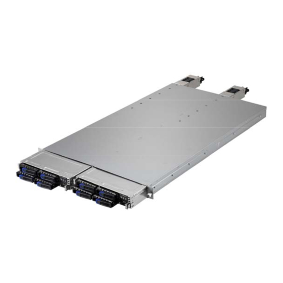
Chapter 1: Overview About the TYAN B7058Y190X2 ® Congratulations on your purchase of the TYAN YR190-B7058X2, a highly optimized rack-mountable barebone system.The YR190-B7058X2 is designed ® ® to support 2 Intel Xeon E5-2600(Sandy Bridge) and E5-2600 V2 (Ivy Bridge) series processor and Up to 64GB UDIMM / 128GB RDIMM / 256GB LRDIMM of DDR3 memory, providing a rich feature set and incredible performance. -
Page 14: Features
Memory channel 4 Channels per CPU Memory voltage 1.5V/ 1.35V PCI-E (1) PCI-E Low-Profile Gen.3 x16 slot Expansion Slots (per Pre-install TYAN Riser M7018-R16-1L, 1U PCI-E x16 riser card blade) Card (right) Port Q'ty Total (3) ports, (1) dedicated for IPMI... - Page 15 (1) YR190-B7058-X2 Barebone Rail kit (1) sliding rail kit for YR190 Manual (1) Quick Installation Guide Installation CD (1) TYAN installation CD Package Contains (2) screw pack / (1) Display Port Others external cable Cable (2) CCBL-0310, US type power cord /...
- Page 16 Memory voltage 1.5V/ 1.35V (1) PCI-E Low-Profile Gen.3 PCI-E x16 slot Expansion Slots (per blade) M7018-R16-1L, 1U PCI-E x16 Pre-install TYAN Riser Card riser card (right) Total (3) ports, (1) dedicated Port Q'ty for IPMI LAN (per blade) Controller Intel I350-AM2...
- Page 17 (1) YR190-B7058-X2 Barebone Barebone Rail kit (1) sliding rail kit for YR190 Manual (1) Quick Installation Guide Package Contains Installation CD (1) TYAN installation CD (2) screw pack / (1) Display Others Port external cable Cable (2) CCBL-0310, US type http://www.tyan.com...
-
Page 18: Product Model
Power Cord power cord / (2) CCBL-0300, EU type power cord Product Model Model HDD Bays Power supply B7058Y190X2-045SV4H (8) 2.5”Hot-swap, (2) 450 Watts (two nodes) SAS/SATA HDDs 80+ Silver B7058Y190X2-045GV4H (8) 2.5”Hot-swap, (2) 450 Watts (two nodes) SAS/SATA HDDs 80+ Gold http://www.tyan.com... -
Page 19: Standard Parts List
Standard Parts List This section describes the B7058Y190X2 package contents and accessories. Open the box carefully and ensure that all components are present and undamaged. The product should arrive packaged as illustrated below. 1.4.1 Box Contents Per Node Component Description... -
Page 20: Accessories
If any items are missing or appear damaged, contact your retailer or ® browse to TYAN ’s website for service: http://www.tyan.com ® The web site also provides information of other TYAN products, as well as FAQs, compatibility lists, BIOS settings, etc. CPU Heatsink x 2 CPU Heatsink x 2 Power Cables... -
Page 21: About The Product
About the Product The following views show you the product. 1.5.1 System Front View (Per Node) http://www.tyan.com... -
Page 22: Led Control And Hdd Led Definitions
Color: Green Color: Red Solid ON OFF Drive present, No Activity Blinking OFF Drive present, With Activity Don’t care Solid ON HDD Fail Don’t care Blinking @1Hz Identify (Locate the HDD) Don’t care Blinking @4Hz SAS/SATA RAID Rebuilding http://www.tyan.com... -
Page 23: System Rear View (Per Node)
Right LED (Link/Activity) (Speed) No Link Solid Green Link 10 Mbps Blinking Green Active Solid Green Solid Green Link 100 Mbps Blinking Green Solid Green Active Solid Green Solid Amber Link 1000 Mbps (1Gbps) Blinking Green Solid Amber Active http://www.tyan.com... - Page 24 Power LED on the front panel and the blue ID LED on the rear panel will light up. The technical personnel can easily locate the system on the rack, disconnect cables from the system, and remove it from the rack for later repair. State Color Description Blue System identified ID LED System not identified http://www.tyan.com...
-
Page 25: Internal View (Per Node)
1.5.5 Internal View (Per Node) Number Description HDD Cage SATA HDD Backplane Board System Fans CPU Sockets Memory Slots Power Distribution Board PCI-E Riser Card Assembly http://www.tyan.com... -
Page 26: Chapter 2: Setting Up
A grounding strap or an anti-static pad Most of the electrical and mechanical connections can be disconnected with your hands. It is recommended that you do not use pliers to remove connectors as it may damage the soft metal or plastic parts of the connectors. http://www.tyan.com... -
Page 27: Precautions
Working on a system that is connected to a power supply can be extremely dangerous. Follow the guidelines below to avoid damage to B7058Y190X2 or injury to yourself. Ground yourself properly before removing the top cover of the system. -
Page 28: Installing Motherboard Components
CPUs, memory modules, HDD and add on cards. 2.1.1 Installing Hard Drives The B7058Y190X2 supports four 2.5” hard drives per node. Follow these instructions to install a hard drive. Warning!!! Always install the hard disk drive to the chassis after the chassis is secured on the rack. - Page 29 Slide the HDD tray out. Unscrew the HDD tray bracket. Place a hard drive into the drive tray. Use four screws to secure the HDD. http://www.tyan.com...
- Page 30 Reinsert the HDD tray into the chassis. Press the locking lever to secure the tray. Repeat the same procedures to install other HDD trays. http://www.tyan.com...
-
Page 31: Installing The Cpu And Heatsink
Follow the steps below to install the processor and heatsink. Locate the CPU socket. 2. Follow steps to pull the CPU lever up to unlock the CPU socket. Open the socket in the direction as shown. Take off the CPU protection cap. http://www.tyan.com... - Page 32 Place the CPU in the CPU socket. Be careful of the golden triangle is in the right direction of the CPU socket. http://www.tyan.com...
- Page 33 Close the socket and press the CPU socket follow steps lever down to secure the CPU. Place the heatsink on top of the CPU and secure it with 4 screws. http://www.tyan.com...
-
Page 34: Installing The Memory
Press the memory slot locking levers in the direction of the arrows as shown in the following illustration. Align the memory module with the slot. When inserted properly, the memory slot locking levers lock automatically onto the indentations at the ends of the module. http://www.tyan.com... - Page 35 http://www.tyan.com...
-
Page 36: Rack Mounting
Sliding rails Screw kit 2.2.1 Installing the Server in a Rack Follow these instructions to mount the TYAN B7058Y190X2 into an industry standard 19” rack. NOTE: Before mounting the TYAN B7058Y190X2 in a rack, ensure that all internal components have been installed and that the unit has been fully tested. -
Page 37: Installing The Inner Rails To The Chassis
2.2.2 Installing the inner Rails to the Chassis Draw out the inner rails from the rail assembly. Install inner rails to the left and right side of chassis. Push the rails forwards to lock the rails in place. http://www.tyan.com... -
Page 38: Installing The Outer Rails To The Rack
/ 2 sets rear) for each side. Secure the rails to the rack as shown. Repeat if you want to install more chassis to the rack. Step 2 To make the installation easier, we suggest that you remove all nodes before you insert the chassis to the rack. http://www.tyan.com... -
Page 39: Rack Mounting The Server
2.2.4 Rack mounting the Server To install the chassis to the rack Lift the chassis and then insert the inner slide rails into the outside rails. Push the chassis back into the rack. http://www.tyan.com... - Page 40 Screw the chassis to the rack. http://www.tyan.com...
- Page 41 Press the locking tabs on both sides of the chassis to pull the chassis out. NOTE: To avoid injury, it is strongly recommended that two people lift the TYAN B7058Y190X2 into the place while a third person screws it to the rack. http://www.tyan.com...
-
Page 42: Chapter 3: Replacing Pre-Installed Components
Introduction This chapter explains how to replace the pre-installed components, including the Motherboard, front panel board, SATA HDD board, M7018-R16-1L PCI-E Riser card, System fans, and Power supply unit etc. Disassembly Flowchart The following flowchart outlines the disassembly procedure. http://www.tyan.com... -
Page 43: Replacing Motherboard Components
Follow Chapter 2.1.1 to pull the node out. 3.3.1 Replacing Expansion Card The B7058Y190X2 has one preinstalled M7018_R16-1L riser card, Follow the instructions below to disassemble the M7018-R16-1L and install a new riser card. Locate the riser card assembly in the chassis. Lift the assembly Unscrew the riser card assembly. - Page 44 Screw the riser card to the assembly and put it back in place. (optional for M7018-R16-1L) Unscrew to replace a new M7018-R16-1L card. Follow the procedures mentioned earlier in reverse order to place the riser card assembly back into the chassis. http://www.tyan.com...
-
Page 45: Disconnecting All Motherboard Cables
3.3.2 Disconnecting All Motherboard Cables Before replacing the motherboard or certain components, remove cables connected to the motherboard. Follow these instructions to remove all motherboard cables. Disconnect all the power, fan and front panel cables. 2. Disconnect SATA cables. http://www.tyan.com... -
Page 46: Removing The Motherboard
After removing all of the aforementioned cables, follow the instructions below to remove the motherboard from the chassis. Remove the heatsink and processor if installed. Remove the nine screws securing the motherboard to the chassis. Carefully lift the motherboard from the chassis. http://www.tyan.com... -
Page 47: Replacing The Power Distribution Board
Replacing the Power Distribution Board Follow these instructions to replace the Power Distribution Board. Disconnect all cables from the power distribution board. Unscrew to take out the power distribution board. Repeat the procedures in reverse to replace a new power distribution board. http://www.tyan.com... -
Page 48: Replacing The Front Panel Board
Replacing the Front Panel Board Follow these instructions to replace the Front Panel board. Release cables from the cable clip. Unscrew the front panel tray. Pull the front panel tray from the chassis. Disconnect cables from the front panel board. http://www.tyan.com... - Page 49 Unscrew to take out the front panel board. 6. Replace a new front panel board and screw it to the front panel tray. 7. Repeat the procedures described earlier in reverse order to place the front panel tray back into place. http://www.tyan.com...
-
Page 50: Front Panel Board Features
1 VCC_USB0 Power connect to 5V (for USB) 6 USB_P1_P USB_P1 + 2 VCC_USB1 Power connect to 5V (for USB) 7 GND Ground 3 USB_P0_N USB_P0 - 8 GND Ground 4 USB_P1_N USB_P1 - 9 NC 5 USB_P0_P USB_P0 + 10 NC http://www.tyan.com... -
Page 51: 3.6 Replacing The System Fan
3.6 Replacing the System Fan Follow these instructions to replace the cooling fans in your system. Locate the cooling fan in your system. Unplug the cable connected to the mainboard. Remove the screws that secure the fan to the system. http://www.tyan.com... - Page 52 Remove the fan from the system. Reinstall the fan(s) into the chassis following the procedures described earlier in reverse order. Connect the fan cable. http://www.tyan.com...
-
Page 53: 3.7 Replacing The Sata Backplane Board
3.7 Replacing the SATA Backplane Board Follow these instructions to replace the SATA Backplane Board in your system. Disconnect one B4P PWR cable and five mini-SAS cables from the backplane board. Unscrew the backplane bracket. Lift the bracket up from the chassis. http://www.tyan.com... - Page 54 Unscrew the backplane board from the bracket. Replace a new SATA Backplane Board and reinstall it into the chassis following the above steps in reverse. http://www.tyan.com...
-
Page 55: Sata Backplane Board Features
3.7.1 SATA Backplane Board Features Front View Rear View Connector Description SATA0~SATA3 SATA Connector J1~J4 HDD Connector Power Connector JTAG CPLD Connector SGPIO SGPIO Connector Platform Select Jumper (reserved) http://www.tyan.com... -
Page 56: Sata Backplane Board Connector Pin Definitions
HDD Connector: J1/J2/J3/J4 Pin NO Pin name Pin NO Pin name SAS_TX+ SAS_TX- SAS_RX- SAS_RX+ VDD_5_RUN SAS_Present_L P8 VDD_5_RUN VDD_5_RUN HD_PRS_L SAS_LED VDD_12_RUN VDD_12_RUN VDD_12_RUN Power Connector: PW1 Pin No. Net Name Description VDD_12_RUN 12V Power Ground Power Ground VDD_5_RUN 5V http://www.tyan.com... - Page 57 SGPIO DataIN 7 SGPIO SMBUS_3V3_DATA_CPLD SMBus Data SAS_GPIO3 SCLOCK SGPIO SAS_GPIO1 DataOUT Ground HD_ERR_LED Pin 1-2 closed: Intel platform Pin 2-3 closed: AMD and LSI platform (default) J12 (reserved) Pin 1-2 closed: beforehand jumper (default) Pin 2-3 closed: beforehand jumper http://www.tyan.com...
-
Page 58: 3.8 Replacing The Power Supply
3.8 Replacing the Power Supply Replace the power supply unit: 1. Press the latch down to pull the power supply out. 2. After replacing a new power supply, push the power supply back into the chassis. http://www.tyan.com... -
Page 59: Chapter 4: Motherboard Information
Caution! To avoid damaging the motherboard and associated components, do not use torque force greater than 7kgf/cm (6.09 lb/in) on each mounting screw for motherboard installation. Do not apply power to the board if it has been damaged. http://www.tyan.com... -
Page 60: Board Image
Board Image This picture is representative of the latest board revision available at the time of publishing. The board you receive may not look exactly like the above picture. http://www.tyan.com... -
Page 61: System Block Diagram
System block diagram http://www.tyan.com... -
Page 62: Motherboard Mechanical Drawing
Motherboard Mechanical Drawing http://www.tyan.com... -
Page 63: Board Parts, Jumpers And Connectors
Board parts, jumpers and connectors http://www.tyan.com... -
Page 64: Jumpers And Connectors
IPMB1 IPMB Connector SGPIO1 SATA SGPIO Connector 2PHD_5 BMC Reset Header 3PHD_6/3PHD_7 COM Select jumper J27/J28/J29 SYS_FAN3/ SYS_FAN2/ SYS_FAN1 PSMI1 PSMI Connector 20-pin Power Connector 4-pin Power Connector IDLED_BTN ID LED Button ID_LED ID LED SATA0~SATA5 Serial ATA Connector http://www.tyan.com... - Page 65 A_USB1 FPIO1 USB1 IPMB1 http://www.tyan.com...
- Page 66 PWR_SW# LAN1LED+ LAN1LED- RST_SW# SMBDATA SMBCLK IDLED_SW# INTRUSION# LAN2LED+ NMI_SW# LAN2LED- USB1: USB Front Panel Header (blue) Signal Signal USBD- USBD- USBD+ USBD+ A_USB1: Vertical (Type A) USB Connectors Signal USBD- USBD+ IPMB1: IPMB Connector Signal Signal BMC_SMB_DATA BMC_SMB_CLK http://www.tyan.com...
- Page 67 SGPIO1 PSMI1 3PHD_7 3PHD_6 2PHD_5 http://www.tyan.com...
- Page 68 SLOAD SCLOCK VCC3_AUX HDD_FAULT SATA0/SATA1/SATA2/SATA3/SATA4/SATA5: SATA Connector Connects to the Serial ATA ready drives via the Serial ATA cable. SATA RX DP SATA RX DN SATA0/SATA1: Support SATA3.0 SATA2/SATA3/SATA4/SATA5: SATA TX DN Support SATA2.0 SATA TX DP PIN7 PIN1 http://www.tyan.com...
- Page 69 IDLED_BTN ID_LED http://www.tyan.com...
- Page 70 System identified System not identified NOTE: The ID LED can be activated remotely using IPMI. Please visit the TYAN Web Site at http://www.tyan.com to download the latest IPMI Configuration Guide for more details. PW1: 20-Pin 12V main PW Connector (Input)
-
Page 71: Thermal Interface Material
CPU lid (applying too much will actually reduce the cooling). NOTE: Always check with the manufacturer of the heat sink & processor to ensure that the thermal interface material is compatible with the processor and meets the manufacturer’s warranty requirements. http://www.tyan.com... -
Page 72: Tips On Installing Motherboard In Chassis
Be especially careful to look for extra stand-offs. If there are any stand-offs present that are not aligned with a mounting hole on the motherboard, it will likely short components on the back of the motherboard when installed. This will cause malfunction and/or damage to your motherboard. http://www.tyan.com... - Page 73 Some chassis include plastic studs instead of metal. Although the plastic studs are usable, MiTAC recommends using metal studs with screws that will fasten the motherboard more securely in place. Below is a chart detailing what the most common motherboard studs look like and how they should be installed. http://www.tyan.com...
-
Page 74: Memory Information
Memory information Before installing memory, ensure that the memory you have is compatible with the motherboard and processor. Check the TYAN Web site at http://www.tyan.com details of the type of memory recommended for your motherboard. The following pictures show common types of DDR3 memory modules. - Page 75 √ √ √ √ CPU0_DIMM_B0 √ √ √ √ √ √ CPU0_DIMM_C0 √ √ √ √ CPU0_DIMM_D0 √ √ CPU1_DIMM_A0 √ √ √ √ √ √ √ CPU1_DIMM_B0 √ √ √ √ √ CPU1_DIMM_C0 √ √ √ CPU1_DIMM_D0 √ http://www.tyan.com...
- Page 76 The speeds are estimated targets and will be verified through simulation. For 3SPC/3DPC -Rank Multiplication (RM) >= 2. DDP -Dual Die Package DRAM stacking. P –Planer monolithic DRAM Die. Romley-EP/EX platform does not support 3DPC when using E5-2400 LRDIMMs. http://www.tyan.com...
- Page 77 Command Address Timing is 1N. QR RDIMM are supported but not validated by Intel/PMO in a homogenous environment. The coverage will have limited system level testing, no signal integrity testing, and no interoperability testing. The passing QR RDIMMs will be web posted. http://www.tyan.com...
-
Page 78: Finishing Up
In the rare circumstance that you have experienced difficulty, you can find help by asking your vendor for assistance. If they are not available for assistance, please find setup information and documentation online at our website or by calling your vendor’s support line. http://www.tyan.com... -
Page 79: Chapter 5: Bios Setup
Select the previous value/setting of the field <+> Select the next value/setting of the field <F8> Load Fail Safe default configuration values of the menu <F3> Load the Optimal default configuration values of the menu <F4> Save and exit <Enter> Execute command or select submenu http://www.tyan.com... - Page 80 BIOS menus are continually changing due to continual BIOS updates over the product lifespan of the motherboard. The BIOS menus provided are current as of the date when this manual was written. Please visit TYAN’s website at http://www.tyan.com for information on BIOS updates available for this specific motherboard.
-
Page 81: Main Menu
It displays BIOS related information. Memory Information This displays the total memory size. System Date Adjust the system date. MM (Months): DD (Days): YYYY (Years) System Time Adjust the system clock. HH (24 hours format): MM (Minutes): SS (Seconds) Access Level Read only. http://www.tyan.com... -
Page 82: Advanced Menu
This section facilitates configuring advanced BIOS options for your system. PCI Settings PCI,PCI-X and PCI Express Settings. ACPI Settings System ACPI Parameters. CPU Configuration CPU Configuration Parameters. Runtime Error Logging Runtime Error Logging Support Setup Options SATA Configuration SATA Devices Configuration. USB Configuration USB Configuration Parameters. http://www.tyan.com... - Page 83 Watchdog Timer Configuration Watchdog Timer Configuration Parameters. Hardware Health Configuration Hardware health Configuration Parameters. Super IO Configuration System Super IO Chip Parameters. Serial Port Console Redirection Serial Port Console Redirection. http://www.tyan.com...
- Page 84 (Only if system supports 64 bit PCI decoding). [Disabled] / [Enabled] Single Root I/O Virtualization Single root I/O virtualization (SR-IOV),SR-IOV is a specification that allows a PCIe device to enable/disable multiple separate physical PCIe devices. [Disabled] / [Enabled] http://www.tyan.com...
- Page 85 Enables or disables System ability to Hibernate (OS/S4 Sleep State). This option may not be effective with some OS. Disabled / Enabled ACPI Sleep State Select the ACPI sleep state the system will enter when the SUSPEND button is pressed. Suspend Disabled / S1 only(CPU Stop Clock) http://www.tyan.com...
- Page 86 Active Processor Cores Number of cores to enable in each processor package. All / 1 / 2 / 3/ 4 / 5 / 6 / 7 / 8 / 9 Limit CPUID Maximum Disabled for Windows XP. Disabled / Enabled http://www.tyan.com...
- Page 87 When enabled, a VMM can utilize the additional hardware capabilities provided by Vanderpool Technology. NOTE: Once the lock bit is set, the contents of this register can not be modified until S5 reset occurs. Enabled / Disabled PPIN Support Enabled / Disabled AES New Instructions (AES-NI) Enabled / Disabled http://www.tyan.com...
- Page 88 5.3.3.1 Socket 0 CPU Information Read only. http://www.tyan.com...
- Page 89 Performance / Balanced performance / Balanced Energy / Energy Efficient Factory Long Duration Power Limit Read only. Long Duration Power Limit Long duration power limit in Watts. Factory Long Duration Maintained Read only. Long Duration Maintained Time window which the long duration power is maintained. http://www.tyan.com...
- Page 90 Recommended short duration power limit Read only. Short duration power limit Short duration power limit in Watts. http://www.tyan.com...
- Page 91 5.3.4 Runtime Error Logging Runtime Error Logging Support Enable/Disable Runtime Error logging Support. http://www.tyan.com...
- Page 92 5.3.5 SATA Configuration http://www.tyan.com...
- Page 93 IDE Mode / AHCI Mode / RAID Mode / Disabled Agressive Link Power Management Enabled / Disabled Port 0/1/2/3/4/5 Hot Plug Enable/Disable SATA Ports Hot Plug Support. Enabled / Disabled External SATA Port 0/1/2/3/4/5 Enabled / Disabled Staggered Spin-up AHCI Supports Staggered Spin-up Enabled / Disabled http://www.tyan.com...
- Page 94 Enables IO port 60h/64h emulation support This should be enabled for the Complete USB keyboard legacy support for non-USB aware OSes. Enabled / Disabled USB transfer time-out The time-out value for Control, Bulk and Interrupt transfers. 20 sec / 10 sec / 5 sec / 1 sec http://www.tyan.com...
- Page 95 Mass storage device emulation type. ’AUTO’ enumerates devices according to their media format. Optical drives are emulated as ’CDROM’, drives with no media will be emulated according to a drive type. Auto / Floppy / Forced FDO / Hard Disk / CD-ROM http://www.tyan.com...
- Page 96 5.3.7– Watchdog Timer Configuration Watchdog mode Disabled / Post / OS / Power On http://www.tyan.com...
- Page 97 On / Off 6.3.8.1 Sensor Data Register Monitoring When you enter the Sensor Data Register Monitoring submenu, you will see the following dialog window pop out. Please wait 8~10 seconds. NOTE 1: SDR can not be modified. Read only. http://www.tyan.com...
- Page 98 http://www.tyan.com...
- Page 99 5.3.9 Super IO Configuration Super IO Chip Read only. http://www.tyan.com...
- Page 100 / IO=2F8h; IRQ=3, 4, 5, 6, 7, 9, 10, 11, 12; / IO=3E8h, IRQ=3, 4, 5, 6, 7, 9, 10, 11, 12; / IO=2E8h, IRQ=3, 4, 5, 6, 7, 9, 10, 11, 12; Change Settings SUART clock source. 24MHz/13 / 24MHz http://www.tyan.com...
- Page 101 Console Redirection Settings The settings specify how the host computer (which the user is using) will exchange data. Both computers should have the same or compatible settings. NOTE: menu only appear when Console Redirection Settings Console Redirection was set to [Enabled]. http://www.tyan.com...
- Page 102 0 if the num of 1’s in the data bits is even. Odd: parity bit is 0 if the num of 1’s in the data bits is odd. Mark: parity bit is always 1. Space: parity bit is always 0. Mark and Space parity do not allow for error detection. http://www.tyan.com...
- Page 103 VT100 / LINUX / XTERMR6 / SCO / ESCN / VT400 Redirection After BIOS POST The settings specify if bootloader is selected than Legacy console redirection is disabled before booting to Legacy OS. Default value is always enable means Legacy. Always enable / Bootloader http://www.tyan.com...
- Page 104 115200 / 9600 / 19200 / 38400 / 57600 Flow Control Flow Control can prevent data loss from buffer overflow. When sending data, if the receiving buffers are full, a ‘stop’ signal can be sent to stop the data flow. Once the http://www.tyan.com...
- Page 105 ‘start’ signal can be sent to restart the flow. Hardware flow control uses two wires to send start/stop signal. None / Hardware RTS/CTS Data Bits / Parity / Stop Bits Read only. http://www.tyan.com...
-
Page 106: Chipset Menu
Chipset Menu North Bridge North Bridge Parameters. South Bridge South Bridge Parameters. Onboard Device Configuration Onboard Device Parameters. ME Subsystem ME Subsystem Configuration http://www.tyan.com... - Page 107 Channel Interleaving Select different Channel Interleaving setting. Auto / 1 Way / 2 Way / 3 Way / 4 Way Rank Interleaving Select different Bank Interleaving setting. Auto / 1 Way / 2 Way / 4 Way / 8 Way http://www.tyan.com...
- Page 108 Memory ECC Enabled / Disabled http://www.tyan.com...
- Page 109 Select number of 1GB contiguous regions to be assigned MMIOH space per CPU. 64G / 1G / 2G / 4G / 8G / 16G / 32G / 64G / 128G MMCFG Base Select the MMCFG BASE Values. 0x80000000 / 0xA0000000 / 0xC0000000 http://www.tyan.com...
- Page 110 Disabled / Enabled ® NOTE: The following items will appear when Intel VT-d is set to [Enabled]. Coherency Support Enable/Disable VT-d Engine Coherency Support. Disabled / Enabled ATS Support Enable/Disable VT-d Engine Address Translation Services support. Enabled / Disabled http://www.tyan.com...
- Page 111 QPI Link Frequency Select Select the QPI Link Frequency. Auto / 6.4GT/s / 7.2GT/s / 8.0GT/s QPI LinkOs Enable/Disable QPI LinkOs. Enabled / Disabled QPI LinkOp Enable/Disable QPI LinkOp. Enabled / Disabled QPI Link1 Enable/Disable QPI Link1. Enabled / Disabled http://www.tyan.com...
- Page 112 5.4.1.3 DIMM Information Submenu Read only. http://www.tyan.com...
- Page 113 Specify what state to go to when power is re-applied after a power failure (G3 state). Power Off / Power On / Last State Onboard SATA RAID OPROM Enable/Disable onboard SATA RAID option rom if Launch Storage OpROM is enabled. Enabled / Disabled http://www.tyan.com...
- Page 114 High Precision Timer Enable/Disable the High Precision Event Timer. Enabled / Disabled http://www.tyan.com...
- Page 115 Onboard LAN I350 Enabled / Disabled LAN1/LAN2 OPROM Enabled / Disabled the LAN Option ROM in the chipset. PXE / iSCSI / None Load PCIe slot 1/2 OPROM Enabled / Disabled PCIe slot 1/2 Link Speed GEN3 / GEN2 / GEN1 http://www.tyan.com...
- Page 116 5.4.4 ME Sub- Menu ME Subsystem Me subsystem Help Enabled / Disabled http://www.tyan.com...
-
Page 117: Server Management
Server Management http://www.tyan.com... - Page 118 Choose options for reactions to a full SEL. Do Nothing / Erase Immediately Log EFI Status Codes Disable the logging of EFI Status Codes or log only error code or only progress code or both. Both / Disabled / Error Code / Progress Code http://www.tyan.com...
- Page 119 5.5.2 BMC Network Configuration Configuration Address Source Select the configure LAN channel parameters statically or dynamically (by BIOS or BMC). Unspecified option will not modify any BMC network parameters during BIOS phase. Unspecified / Static / Dynamic-Obtained by BMC http://www.tyan.com...
-
Page 120: Boot
Option ROM Messages Select display mode for Option ROM. Force BIOS / Keep Current INT19 Trap Response BIOS reaction on INT19 trapping by option ROM: IMMEDIATE-execute the trap right away; POSTPONED-execute the trap during legacy boot. Immediate / Postponed http://www.tyan.com... - Page 121 Round-robin Disabled / Enabled Boot Option #1/Boot Option #2/ Boot Option #3 Select the first boot device. Device Name / Disabled 5.6.1 Hard Drive BBS Priorities Configuration Boot Option #1 Sets the system boot order. Device Name / Disabled http://www.tyan.com...
- Page 122 Do not launch / UEFI only / Legacy only / Legacy first / UEFI first Launch Video OpROM policy Controls the execution of UEFI and Legacy Storage opRom Do not launch / UEFI only / Legacy only / Legacy first / UEFI first http://www.tyan.com...
- Page 123 Other PCI devices ROM priority For PCI devices other than network, Mass storage or video defines which OpROM to launch UEFI opROM / Legacy opROM http://www.tyan.com...
-
Page 124: Security
Confirm New Password window will pop out to ask for confirmation. User Password Set user password in the Create New Password window. After you key in the password, the Confirm New Password window will pop out to ask for confirmation. http://www.tyan.com... -
Page 125: Save & Exit
Discard Changes and Reset Reset system setup without saving any changes. Save Options Read only. Save Changes Save changes done so far to any of the setup options. Discard Changes Discard changes done so far to any of the setup options. http://www.tyan.com... - Page 126 Restore Defaults Restore/Load Default values for all the setup options. Save as User Defaults Save the changes done so far as User Defaults. Restore User Defaults Restore the User Defaults to all the setup options. http://www.tyan.com...
-
Page 127: Chapter 6: Diagnostics
BIOS flash failure, you must contact your dealer for a replacement BIOS. There are no exceptions. TYAN does not have a policy for replacing BIOS chips directly with end users. In no event will TYAN be held responsible for damages done by the end user. -
Page 128: Amibios Post Code (Aptio)
Power on. Reset type detection (soft/hard). 0x02 AP initialization before microcode loading 0x03 North Bridge initialization before microcode loading 0x04 South Bridge initialization before microcode loading 0x05 OEM initialization before microcode loading 0x06 Microcode loading 0x07 AP initialization after microcode loading http://www.tyan.com... - Page 129 South Bridge initialization after microcode loading 0x0A OEM initialization after microcode loading 0x0B Cache initialization SEC Error Codes 0x0C – 0x0D Reserved for future AMI SEC error codes 0x0E Microcode not found 0x0F Microcode not found SEC Phase None http://www.tyan.com...
- Page 130 Memory initialization. Configuring memory 0x2F Memory initialization (other) 0x30 Reserved for ASL (see ASL Status Codes section below) 0x31 Memory Installed 0x32 CPU post-memory initialization is started. 0x33 CPU post-memory initialization. Cache initialization 0x34 CPU post-memory initialization. Application Processor(s) (AP) http://www.tyan.com...
- Page 131 0x54 Unspecified memory initialization error 0x55 Memory not installed 0x56 Invalid CPU type or speed 0x57 CPU mismatch 0x58 CPU self test failed or possible CPU cache error 0x59 CPU microcode is not found or microcode update is failed. http://www.tyan.com...
- Page 132 Recovery firmware image is loaded. 0xF5 – 0xF7 Reserved for future AMI progress codes Recovery Error Codes 0xF8 Recovery PPI is not available. 0xF9 Recovery capsule is not found. 0xFA Invalid recovery capsule 0xFB – 0xFF Reserved for future AMI error codes http://www.tyan.com...
- Page 133 North Bridge DXE initialization (North Bridge module specific) 0x6D North Bridge DXE initialization (North Bridge module specific) 0x6E North Bridge DXE initialization (North Bridge module specific) 0x6F North Bridge DXE initialization (North Bridge module specific) 0x70 South Bridge DXE initialization is started. http://www.tyan.com...
- Page 134 0x99 Super IO initialization 0x9A USB initialization is started. 0x9B USB Reset 0x9C USB Detect 0x9D USB Enable 0x9E -0x9F Reserved for future AMI codes 0xA0 IDE initialization is started 0xA1 IDE Reset 0xA2 IDE Detect 0xA3 IDE Enable http://www.tyan.com...
- Page 135 North Bridge initialization error 0xD2 South Bridge initialization error 0xD3 Some of the Architectural Protocols are not available 0xD4 PCI resource allocation error. Out of Resources 0xD5 No Space for Legacy Option ROM 0xD6 No Console Output Devices are found. http://www.tyan.com...
- Page 136 System is waking up from the S3 sleep state. 0x40 System is waking up from the S4 sleep state. System has transitioned into ACPI mode. Interrupt controller is in 0xAC APIC mode. System has transitioned into ACPI mode. Interrupt controller is in 0xAA APIC mode. http://www.tyan.com...
- Page 137 NOTE http://www.tyan.com...
-
Page 138: Appendix I: Cable Connection Tables
Connect to S7058 MB Board → SATA0 → SATA1 SATA Cable → SATA2 → SATA3 3. B4P PWR and SGPIO Cable SATA/SAS BP Board to S7058 MB SATA/SAS BP Connect to S7058MB Board → B4P Cable → SGPIO Cable SGPIO1 http://www.tyan.com... - Page 139 Front Panel Board (FPB) to S7058 MB Connect to S7058 MB → Control Cable FPIO1 → USB Cable USB1 5. 2X10P PWR & PSMI Cable PDB Board to S7058 MB PDB Board Connect to S7058 MB 2X10P PWR → Cable → PSMI Cable PSMI1 http://www.tyan.com...
-
Page 140: Appendix Ii: Fru Parts Table
Cable A/C Power Cord, L=1830mm, CCBL-0317 332810000397 US type A/C Power Cord, L=1830mm, CCBL-0300 332810000281 EU type 3Y YM-2451CE01R, 450W, Power CPSU-0430 471100000132 1U(B7058Y190X2-045SV4H sku) Power Supply 3Y YM-2451GA01R, 450W, FRU-PS-0050 471100000105 1U(B7058Y190X2-045GV4H sku) CFAN-0068 336252012277 40X40X56MM Rack CRAL-0170 340786900010... - Page 141 (rpm) Temp Sensor: PCH_Area_Temp, M/B_Air_Inlet (Q127) M/B_Air_outlet (Q126). They detect the system temperature around. NOTE: The system temperature is measured in a scale defined by Intel, not in Fahrenheit or Celsius. http://www.tyan.com...
- Page 142 BIOS Temp Sensor Name Explanation: http://www.tyan.com...
- Page 143 Fan speed of CPU0_FAN CPU1_FAN Fan speed of CPU1_FAN SYS_FAN_1 Fan speed of SYS_FAN_1 SYS_FAN_2 Fan speed of SYS_FAN_2 SYS_FAN_3 Fan speed of SYS_FAN_3 SYS_FAN_4 Fan speed of SYS_FAN_4 SYS_FAN_5 Fan speed of SYS_FAN_5 SYS_FAN_6 Fan speed of SYS_FAN_6 http://www.tyan.com...
-
Page 144: Appendix Iii: Technical Support
MiTAC serves multiple market segments with the industry’s most competitive services to support them. TYAN's tech support is some of the most impressive we've seen, with great response time and exceptional organization in general.” — Anandtech.com Please feel free to contact us directly for this service at tech-support@tyan.com... - Page 145 (RMA) number. The RMA number Should be prominently displayed on the outside of the shipping carton and the package should be mailed prepaid. ® TYAN will pay to have the board shipped back to you. ® TYAN B7058Y190X2 Service Engineer’s Manual V1.0 Document No.: D2241 - 100 http://www.tyan.com...
Need help?
Do you have a question about the B7058Y190X2 and is the answer not in the manual?
Questions and answers