Table of Contents
Advertisement
Quick Links
Advertisement
Table of Contents

Subscribe to Our Youtube Channel
Related Manuals for TYAN YR190-B8228


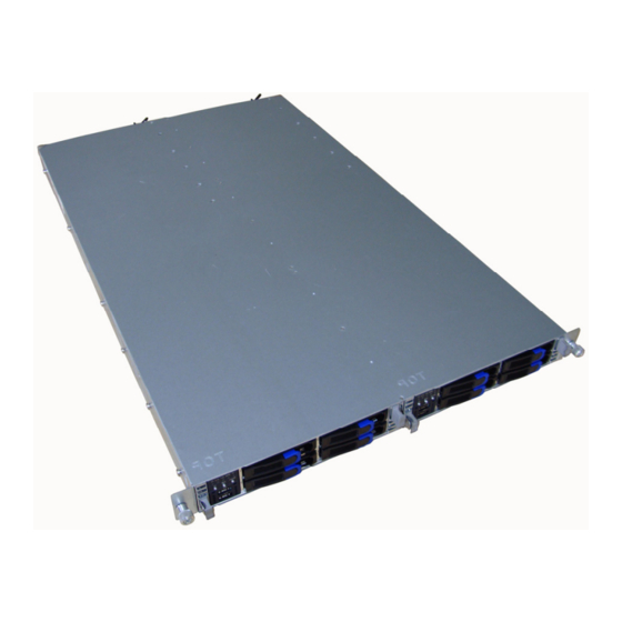
Summary of Contents for TYAN YR190-B8228
- Page 1 YR190-B8228 Service Engineer’s Manual...
- Page 3 Corporation and has been reviewed for accuracy and reliability prior to printing. MiTAC assumes no liability whatsoever, and disclaims any ® express or implied warranty, relating to sale and/or use of TYAN products including liability or warranties relating to fitness for a particular purpose or merchantability.
- Page 4 There will be danger of explosion if battery is incorrectly replaced. Replace only with the same or equivalent type recommended by manufacturer. Dispose of used battery according to manufacturer instructions and in accordance with your local regulations. http://www.tyan.com...
- Page 5 About this Manual ® This manual provides you with instructions on installing your TYAN YR190-B8228. This Manual is intended for experienced users and integrators with hardware knowledge of personal computers. This manual consists of the following parts: ® Chapter1: Provides an introduction to the TYAN...
- Page 6 Safety and Compliance Information ® Before installing and using TYAN YR190-B8228, take note of the following precautions: ·Read all instructions carefully. ·Do not place the unit on an unstable surface, cart, or stand. ·Do not block the slots and opening on the unit, which are provided for ventilation.
- Page 7 General Precautions ·Follow all caution and warning instructions marked on the equipment and explained in the accompanying equipment documentation. Machine Room Environment ·Make sure that the area in which you install the system is properly ventilated and climate-controlled. http://www.tyan.com...
- Page 8 ·Make sure only one component is extended at a time. A rack might become unstable if more than one component is extended. To avoid damage to the equipment: ·The rack width and depth must allow for proper serviceability and cable http://www.tyan.com...
- Page 9 ·Do not pull on a cord or cable. When unplugging from the electrical outlet, grasp the cord by the plug. · T o reduce the risk of electrical shock, disconnect all power cords before servicing the appliance. http://www.tyan.com...
- Page 10 AC electrical outlet and refer servicing to an authorized service provider. Examples of damage requiring service include: – The power cord, extension cord, or plug has been damaged. – Liquid has been spilled on the product or an object has fallen into the product. http://www.tyan.com...
- Page 11 – The product has been exposed to rain or water. – The product has been dropped or damaged. – The product does not operate normally when you follow the operating instructions. http://www.tyan.com...
- Page 12 http://www.tyan.com...
-
Page 13: Table Of Contents
Table of Contents Chapter 1: Overview ............... 15 1.1 About the TYAN YR190-B8228..........15 1.2 Product Model ................15 1.3 Features ................... 16 1.4 Standard Parts List ..............19 1.5 About the Product..............21 Chapter 2: Setting Up..............27 2.1 Installing Motherboard Components ........29 2.1.1 Installing Hard Drives ............... - Page 14 Appendix I: Cable Connection Tables........105 Appendix II: FRU Parts Table............ 107 Appendix III: Technical Support ..........109 http://www.tyan.com...
-
Page 15: Chapter 1: Overview
Chapter 1: Overview About the TYAN YR190-B8228 ® Congratulations on your purchase of the TYAN YR190-B8228, a highly optimized rack-mountable barebone system. The YR190-B8228 is designed to support 2 AMD Opteron™ 4000 series Processor and support 12 R/UDDR3 DIMM sockets (per node), dual Channel R/U DDR3 667/800/1066/1333 , providing a rich feature set and incredible performance. -
Page 16: Features
Super I/O Winbond W83627 Supported DIMM Qty (6)+(6) DIMM slots DIMM Type / Speed U/RDDR3 667/800/1066/1333 MHz Memory (per Capacity Up to 96GB RDIMM / 48GB UDIMM blade) Memory channel 2 Channels per CPU Memory voltage 1.5V/ 1.35V http://www.tyan.com... - Page 17 PCI-E (1) PCI-E Low-Profile Gen.2 x16 slot Pre-install TYAN Riser M7018-R16-1L, 1U PCI-E x16 riser Card card (right) Expansion Slots (per blade) Max. HBA Dimension (1) 68.90mm x 167.65mm (HH/HL) (H x L) Port Qty Total (3) ports, (1) dedicated for IPMI...
- Page 18 (2) CCBL-0310, US type power cord / Cable Power Cord (2) CCBL-0300, EU type power cord This is the condition when writing the manual, please take the material object as standard, for the latest handbook please browse to TYAN’s website: http://www.tyan.com. http://www.tyan.com...
-
Page 19: Standard Parts List
The product should arrive packaged as illustrated below. 1.4.1 Box Contents Per Node Component Description 1U chassis, 2 nodes (4) hot swap HDD bays per node ® TYAN S8228 system board (pre-installed) single 450Watts(100V~240VAC) Power Supply (pre-installed) (1) 40x28mm System FAN (pre-installed) - Page 20 If any items are missing or appear damaged, contact your retailer or browse to TYAN’s website for service: http://www.tyan.com ® The website also provides information of other TYAN products, as well as FAQs, compatibility lists, BIOS settings, etc. The samples we've provided in this manual are for reference only.
-
Page 21: About The Product
LAN2 LED Power button HDD LED Reset button Power button ID button USB port 1.5.2 System Rear View (Per Node) LAN 3 Share with Expansion slots IPMI Port LAN 1 LAN 2 USB Ports VGA Port COM Port ID LED http://www.tyan.com... - Page 22 ID LED LAN1/LAN2 Green Link Activity Green (Blinking) Activity Green Ready HDD LED Green (Blinking) Activity Green Normal Status Amber System Failed Fan failed, system IPMI LED Without IPMI module thermal. IPMI fault alert event With IPMI module is raised. http://www.tyan.com...
- Page 23 Note: Press ID button when the system is AC (Alternating Current) on, then ID LED will show the system is identified with emitting blue light. Users from remote site could also activate ID LED by input a few commands in IPMI, detailed software support please visit http://www.tyan.com for lastest AST2050 user guide. http://www.tyan.com...
- Page 24 1.5.4 Internal View (Per Node) Number Description HDD Cage SATA HDD Backplane Board System Fans& Mylar Memory CPU Socket PCI-E Riser Card Mylar PCI-E Riser Card Assembly Power Distribution Board Power Supply http://www.tyan.com...
- Page 25 1.5.5 Motherboard (S8228) Layout The diagram is representative of the latest board revision available at the time of publishing. The board you receive may not look exactly like the above diagram. http://www.tyan.com...
- Page 26 1.5.6 System Block Diagram S8228 Block Diagram (Represents all SKUs) http://www.tyan.com...
-
Page 27: Chapter 2: Setting Up
A grounding strap or an anti-static pad Most of the electrical and mechanical connections can be disconnected with your hands. It is recommended that you do not use pliers to remove connectors as it may damage the soft metal or plastic parts of the connectors. http://www.tyan.com... - Page 28 Metallic parts or metal flakes can cause electrical shorts. All connectors are keyed to only attach one way. All use the correct screw size as indicated in the procedures. http://www.tyan.com...
-
Page 29: Installing Motherboard Components
The YR190-B8228 supports four 2.5” hard drives per node. Follow these instructions to install a hard drive. Press the locking tabs at both sides to pull the node out. Press the locking lever latch and pull the locking lever open. http://www.tyan.com... - Page 30 3. Slide the HDD tray out. 4.Unscrew the HDD tray bracket. 5. Place a hard drive into the drive tray. Use four screws to secure the HDD. http://www.tyan.com...
- Page 31 6 Reinsert the HDD tray into the chassis. Press the locking lever to secure the tray. Repeat the same procedures to install other HDD trays. http://www.tyan.com...
-
Page 32: Installing The Cpu And Heatsink
Follow the steps below to install the processor and heatsink. 1. Locate the CPU socket. 2. Press the lever and unlock socket. 3. Lift the CPU protection cap up and lay the CPU into the socket(A), ensuring pin1 is correctly located (B). http://www.tyan.com... - Page 33 4. Close the socket cover and press the CPU lever down to secure the CPU. 5. Place the heatsink on top of the CPU and secure it with 2 screws. http://www.tyan.com...
-
Page 34: Installing The Memory
Press the memory slot locking levers in the direction of the arrows as shown in the following illustration. Align the memory module with the slot. When inserted properly, the memory slot locking levers lock automatically onto the indentations at the ends of the module. http://www.tyan.com... - Page 35 2). Refer to the memory population option table for recommended memory installation instruction. Recommended Memory Population Table ( Registered ) ® To achieve the best performance, TYAN strongly recommended memory installation configuration as listed below: Registered Dimm Single CPU Dual CPU...
- Page 36 CPU1 DIMM6 CHB0 CPU1 DIMM7 CHB1 √ √ CPU1 DIMM8 CHB2 √ CPU1 DIMM9 CHA0 CPU1 DIMM10 CHA1 √ √ CPU1 DIMM11 CHA2 Note: 1). “√”indicates a populated DIMM slot. 2). If installing only one processor, you should choose CPU0 http://www.tyan.com...
-
Page 37: Rack Mounting
2.2.1 Installing the Server in a Rack Follow these instructions to mount the TYAN YR190-B8228 into an industry standard 19” rack. NOTE: Before mounting the TYAN YR190-B8228 in a rack, ensure that all internal components have been installed and that the unit has been fully tested. -
Page 38: Installing The Inner Rails To The Chassis
2.2.2 Installing the inner Rails to the Chassis 1. Draw out the inner rails from the rail assembly. Install inner rails to left and right side of chassis. 2. Push the rails forwards to lock the rails in place. http://www.tyan.com... -
Page 39: Installing The Outer Rails To The Rack
(2 sets front / 2 sets rear) for each side. Secure the rails to the rack as shown.) 3. Repeat Step 2 if you want to install more chassis to the rack. 4. To make the installation easier, we suggest that you remove all nodes before you insert the chassis to the rack. http://www.tyan.com... -
Page 40: Rack Mounting The Server
2.2.4 Rack mounting the Server To install the chassis to the rack 1. Lift the chassis and then insert the inner slide rails into the outside rails. 2. Push the chassis into the rack. http://www.tyan.com... - Page 41 3. Screw the chassis to the rack. 4. Insert the node into the chassis. 5. Repeat Step 4 for the second node. To remove the chassis from the rack 1. Remove the nodes. 2. Unscrew the chassis. http://www.tyan.com...
- Page 42 3. Press the locking tabs on both sides of the chassis to pull the chassis out. Note: To avoid injury, it is strongly recommended that two people lift the TYAN YR190-B8228 into the place while a third person screws it to the rack. http://www.tyan.com...
-
Page 43: Chapter 3: Replacing Pre-Installed Components
Introduction This chapter explains how to replace the pre-installed components, including the M7018-R16-1L Riser card, System fans, and Power supply unit etc. Disassembly Flowchart The following flowchart outlines the disassembly procedure. Components Riser card System Fan Power Supply Mainboard http://www.tyan.com... -
Page 44: Replacing Expansion Card
① to disassemble the riser card assembly, ② to install a new PCI-E card. ③ to replace a new riser card. Locate the riser card assembly in the chassis. Unscrew the riser card assembly to lift the assembly up. Unscrew to remove the PCI-E bracket. http://www.tyan.com... - Page 45 Install a low-profile PCIE card onto the assembly. Put the assembly back in place and screw it to the chassis. Unscrew to replace a new M7018-R16-1L riser card. Repeat the procedures 3~4 mentioned earlier order to place the riser card assembly back into the chassis. http://www.tyan.com...
-
Page 46: Sata Backplane Board Features
When customer uses 4 SATA connectors with Native IDE mode, we suggest to install OS on SATA2 (J12),please refer to 1.5.5 Motherboard Placement Hard disk, and make SATA0, SATA1, SATA3 as data disk to get the best hard disk IO performance. http://www.tyan.com... -
Page 47: Replacing The System Fan
Follow these instructions to replace the cooling fans in your system. Locate the cooling fans in your system. Pull off the fan mylar. Unplug the cables connected to the mainboard and lift the fan unit up from the chassis. http://www.tyan.com... - Page 48 Use a flat-head screw driver to push the screws open. Replace a new fan and use the screw driver to push the screw back into the screw hole. Reinstall the fans into the chassis following the procedures described earlier in reverse order. Connect the fan cables. http://www.tyan.com...
-
Page 49: Replacing The Power Supply
Replacing the Power Supply 1. Press and hold the latch to pull the power supply out. 2. After replacing a new power supply, press and hold the latch to push the power supply back into the chassis. http://www.tyan.com... -
Page 50: Disconnecting All Motherboard Cables
Disconnecting All Motherboard Cables Before replacing the motherboard , remove cables connected to the motherboard. Follow these instructions to remove all motherboard cables. Disconnect all the power and fan cables. 2. Disconnect SATA cables and front panel cable. http://www.tyan.com... -
Page 51: Removing The Motherboard
After removing all of the aforementioned cables, follow the instructions below to remove the motherboard from the chassis. Remove the heatsink and processor if installed. Remove the nine screws securing the motherboard to the chassis. Carefully lift the motherboard from the chassis http://www.tyan.com... - Page 52 NOTE http://www.tyan.com...
-
Page 53: Chapter 4: Bios Setting
The menu bar at the top of the windows lists these selections: Main To configure basic system setups Advanced To configure the advanced chipset features Boot To configure system boot order Security To configure user and supervisor passwords Chipset To configure chipset management features Exit To exit setup utility http://www.tyan.com... -
Page 54: Setup Basics
Chipset section unless you are absolutely sure of what you are doing. The Chipset ® defaults have been carefully chosen either by TYAN or your system manufacturer for best performance and reliability. Even a seemingly small change to the Chipset setup options may cause the system to become unstable or unusable. -
Page 55: Bios Main Menu
When an option is selected in the left frame, it is highlighted in white. Often, a text message will accompany it. Feature Option Description Main System Time HH : MM : SS Set the system time System Date MM : DD : YYYY Set the system date http://www.tyan.com... -
Page 56: Bios Advanced Menu
IPMI configuration including IPMI 2.0 Configuration Menu Item server monitoring and event log Remote Access Menu Item Configure Remote Access Configuration USB Configuration Menu Item Configure the USB support Hyper Transport Configure Coherent and Non Menu Item Configuration coherent HT Link http://www.tyan.com... -
Page 57: Cpu Configuration
You can use this screen to view CPU Configuration Menu. Use the up and down arrow (/) keys to select an item. Use the Plus and Minus (+/-) keys to change the value of the selected option. The settings are described on the following pages. http://www.tyan.com... - Page 58 Disabled Enabled IO prefetch Enable or Disable IO prefetch Disabled Allow user disable Multiple No Leveling CPU Cores Once disabled, it CPU Core Level Power of 2 cores cannot be added back without 1/2/3/4/5/6 cores a cold reset. http://www.tyan.com...
-
Page 59: Ide Configuration
Keys to change the value of the selection options. Feature Option Description disables the integrated IDE Disabled Controller enables only the Primary IDE Onboard PCI Primary Controller IDE Controller enables only the Secondary IDE Secondary Controller Both enables both IDE Controller http://www.tyan.com... - Page 60 4.7.2.1 - IDE Configuration Sub-Menu http://www.tyan.com...
- Page 61 SWDMAn: Single Word DMAn MWDMAn: Multi Word DMAn UDMAn: UltraDMAn Auto S. M. A. R. T stands for Disabled S. M. A. R. T Self-Monitoring,Analysis and Enabled Reporting Technology. Disabled 32 Bit Data Enable/Disable 32-bit Data transfer Transfer Enabled http://www.tyan.com...
- Page 62 3F8 IRQ4 Address Addresses. 2E8 IRQ3 Disabled POST: BIOS POST Watchdog timer counting, start at Power On stop at OS boot. POST Watchdog Mode OS: OS boot watchdog, start at OS boot. Power On: Start at Power On Power ON http://www.tyan.com...
- Page 63 Use the Plus and Minus (+/-) keys to change the value of the selected option. A description of the selected item appears on the right side of the screen. The settings are described on this page. The screen is shown below. http://www.tyan.com...
- Page 64 4.7.4.1 – General ACPI Configuration sub-menu 4.7.4.2 – Advanced ACPI Configuration sub-menu http://www.tyan.com...
- Page 65 Include ACPI APIC table pointer to ACPI APIC Support RSDT pointer list. Enabled Disabled Include OEMB table pointer to R(X) AMI OEMB table SDT pointer lists. Enabled Disabled Enable/Disable Headless operation Headless mode mode through ACPI. Enabled 4.7.4.3 – Advanced ACPI Configuration sub-menu http://www.tyan.com...
- Page 66 Select Smart FAN mode Enabled 30%Duty Cycle This item allows you to set CPU FAN Min Duty Cycle minimum PWM Duty Cycle NOTE: CPU FAN Min Duty Cycle is hidden and will appear when Auto FAN Power Control is set to [Enabled]. http://www.tyan.com...
- Page 67 4.7.5.1 - Sensor Data Configuration Sub-Menu Read only. It can not be modified in user mode. http://www.tyan.com...
- Page 68 The settings are described on the following pages. Feature Option Description IPMI 2.0 Configuration BMC Firmware Read only ------ Status of BMC Read only ------ Clear BMC System Event [Enter] Clear all events in BMC System Event Log. BMC Alert Beep BMC Alert Beep On/Off http://www.tyan.com...
- Page 69 4.7.6.1 View BMC System Event Log Sub-Menu Read only. It can not be modified in user mode. http://www.tyan.com...
- Page 70 4.7.6.2 LAN Configuration Sub-Menu http://www.tyan.com...
- Page 71 Feature Option Description Set up LAN Configuration DHCP IP address source IPMI IP Address Source STATIC After setup LAN Configure need select Save LAN Configuration [Enter] Save LAN Configuration and choice【ok】 to enable changes. 4.7.6.3 Set PEF Configuration Sub-Menu http://www.tyan.com...
- Page 72 Power Cycle OEM Action Diagnostic Int Disabled Alert Startup Delay Enable or Disable Alert Startup Delay Enabled Disabled Startup Delay Enable or Disable Startup Delay Enabled Enabled Event Message For Enable or Disable Event Msg Delay PEF Action Disabled http://www.tyan.com...
- Page 73 The settings are described on the following pages. Feature Option Description Configure Remote Access type and parameters Disabled Remote Access Select Remote Access type Enabled NOTE: The following BIOS items are available only when Remote Access is set to [Enabled]. http://www.tyan.com...
- Page 74 VT-UTF8 Enable VT-UFT8 Combination Enabled VT-UTF8 Combo Key Key Support for ANSI/VT100 Support terminals. Disabled No Delay Sredir Memory Display Delay 1 Sec Gives the delay in seconds to Delay display memory information. Delay 2 Sec Delay 4 Sec http://www.tyan.com...
- Page 75 OSes without EHCI hand-off BIOS EHCI Hand-Off support. The EHCI ownership change should claim by EHCI Disabled driver. Disabled Legacy USB1.1 HC Support USB1.1 HC Enabled Support AUTO Disabled 1 port USB port Enable1//2/4/6 Ports in OS 2 port 4port 6ports http://www.tyan.com...
- Page 76 You can use this screen to view the Trusted Computing Configuration Menu. Use the up and down arrow (/) keys to select an item. Use the Plus and Minus (+/-) keys to change the value of the selected option. The settings are described on the following pages. http://www.tyan.com...
- Page 77 1.6GHz Link Speed to the system clock and the board is 1.8GHz capable. 2.0GHz 2.2GHz 2.4GHz 2.6GHz Auto Non-Coherent HT The HyperTransport link will run at Link Width this Width. 4bit/8bit/16bit http://www.tyan.com...
-
Page 78: Boot Menu
4.8 - Boot Menu You can display Boot Setup option by highlighting it using the Arrow (/) keys and pressing Enter. The settings are described on the following pages. http://www.tyan.com... - Page 79 Enabled: displays OEM log instead Enabled of POST messages. Enabled Waits for F1 key to be present if Wait for ‘F1’ If Error error occurs. Disabled Enabled Displays “Press DEL to run Setup” Hit ‘DEL’ Message Display in POST. Disabled http://www.tyan.com...
-
Page 80: Boot Device Priority
(/) keys to select an item. Use the Plus and Minus (+/-) keys to change the value of the selected option. Feature Option Description Boot Device Priority Network: IBA GE Slot 0200 v1335 Specifies the boot 1st Boot Device sequence from the available devices. Disabled http://www.tyan.com... - Page 81 Network: IBA GE Slot 0301 v1335 available devices. Disabled Network: IBA GE Slot 0200 v1335 Specifies the boot Network: IBA GE Slot 0300 v1335 sequence from the 3 nd Drive Network: IBA GE Slot 0301 v1335 available devices. Disabled http://www.tyan.com...
-
Page 82: Security Menu
Installed displays. If no User Password: password is set, Not Installed Installed displays. Change Supervisor Selects this option to change or [Enter] Password install Supervisor Password. Selects this option to change or Change User Password [Enter] install User Password. http://www.tyan.com... -
Page 83: Chipset Menu
4.10 - Chipset Menu This menu allows the user to customize functions of the AMD Chipsets. Select a menu by highlighting it using the Arrow (/) keys and pressing Enter. The settings are described on the following pages. http://www.tyan.com... - Page 84 4.10.1 – NorthBridge Chipset Configuration Sub- Menu http://www.tyan.com...
- Page 85 Enable Node Memory Node Interleaving Interleaving Disabled Auto Enable Channel Memory Channel Interleaving Interleaving Disabled Disabled Reserve a spare memory rank CS Sparing Enable in each mode Enabled Disabled Enable or disable bank swizzle Bank Swizzle Mode mode Enabled http://www.tyan.com...
- Page 86 8 hours. user DRAM ECC Enable Enabled DRAM SCRUB REDIRECT Enabled DRAM BG Scrub 1.31ms Only read Data Cache BG Scrub Disabled L2 Cache BG Scrub Disabled L3 Cache BG Scrub Disabled http://www.tyan.com...
- Page 87 4.10.2 - Southbridge Configuration Sub-Menu This menu gives options for southbridge devices settings. Select a menu by highlighting it using the Arrow (/) keys and pressing Enter. The settings are described on the following pages. http://www.tyan.com...
- Page 88 This one is the AC power Power On sudden power failure shut down the computer. When Restore on AC Power the electricity came to shut Power off Loss down when computer is booting. The Last state setting are off/on/last state. http://www.tyan.com...
- Page 89 Option Description SR5650 Configuration Disabled Disable or Enable IOMMU IOMMU function. Enabled Video card scan from PCIE PCIE GPP1-PCI bus to PCI bus Primary Video Controller Video card scan from PCI bus PCI-PCIE GPP1 (onboard VGA) to PCIE bus. http://www.tyan.com...
- Page 90 4.10.3.1 – PCI Express Configuration Sub-Menu http://www.tyan.com...
- Page 91 Advertised RC Disabled For ATI GFX Card: Link ASPM M2x-use ASPM L1 only L0s & L1 M5x-use both ASPM L0 L0s Downstream L0sDownstream*L1 Slot Power Limit, W ---- Disabled When Enabled L1 will L1 Immediate ACK beACK’d immediately Enabled http://www.tyan.com...
- Page 92 Gen2 Mode Software Initiated capability Advertised RC Disabled For ATI GFXCard: Link ASPM M2x-use ASPM L1 only L0s & L1 M5x-use both ASPM L0 L0s Downstream L0sDownstream*L1 Disabled When Enabled L1 will be L1 Immediate ACK ACK’d immediately Enabled http://www.tyan.com...
- Page 93 Advertize Gen2 Software Initiated capability Advertised RC Disabled For ATI GFX Card: Link ASPM M2x-use ASPM L1 only L0s & L1 M5x-use both ASPM L0 L0s Downstream L0sDownstream*L1 When Enabled L1will Disabled L1 Immediate ACK be ACK’d Enabled immediately http://www.tyan.com...
- Page 94 NB-SB Port: Feature Option Description NB-SB Port Features Disabled NB-SB Link ASPM NB-SB Link ASPM Auto Link Width Select the Link Width x1/x2/x4 GPP1 Core: http://www.tyan.com...
- Page 95 Feature Option Description GPP1 Core Disabled Turn Off PLL During L1/L23 Enable Disabled TXCLK Clock Gating in L1 ----- Enable Disabled LCLK Clock Gating in L1 Enable GPP3a Core: http://www.tyan.com...
- Page 96 Feature Option Description GPP3a Core Disabled Turn Off PLL During L1/L23 Enable Disabled TXCLK Clock Gating in L1 ----- Enable Disabled LCLK Clock Gating in L1 Enable http://www.tyan.com...
- Page 97 SB Core: Feature Option Description SB Core Disabled TXCLK Clock Gating in L1 Enable ----- Disabled LCLK Clock Gating in L1 Enable http://www.tyan.com...
- Page 98 Disabled Disable or Enable the Enabled with OPROM onboard 82574 NIC1 with Onboard 82576 NIC1 /without oprom. Enabled without OPROM Disabled Disable or Enable the Onboard 82576 NIC2 Enabled with OPROM onboard 82574 NIC2with /without oprom. Enabled without OPROM http://www.tyan.com...
-
Page 99: Exit Menu
Use this option to load default performance setup values. Use this option when system CMOS values have been corrupted or modified incorrectly. Load Failsafe Defaults Use this option to load all default failsafe setup values. Use this option when troubleshooting. http://www.tyan.com... -
Page 100: Bios Differences
The BIOS of B8228 is similar to S8228 while there are some differences in menus. The following table displays those differences in details. For a complete review of S8228 BIOS, please refer to the motherboard manual. 1.BIOS Version information S8228: http://www.tyan.com... - Page 101 B8228: 2.FAN Configuration Sub-Men S8228: http://www.tyan.com...
- Page 102 http://www.tyan.com...
- Page 103 B8228: http://www.tyan.com...
- Page 104 Table of Differences B8228 S8228 Version VX.XX.B10 VX.XX CPU FAN MIN Duty Cycle http://www.tyan.com...
-
Page 105: Appendix I: Cable Connection Tables
SATA/SAS Backplane (BP) Board to S8228 MB SATA/SAS BP Cable Connect to S8228 MB Board → → SATA Cable → → → SGPIO Cable 3. B4P PWR Cable SATA/SAS Backplane (BP) Board to S8228 MB SATA/SAS BP Connect to S8228MB Board → B4P Cable http://www.tyan.com... - Page 106 4. FP Ctrl and USB Cable Front Panel Board (FPB) to S8228 MB Connect to S8228 MB → Control Cable → USB Cable 5. Power Supply Cables PDB to S8228 MB Connect to S8228 MB → 2X10P PWR → PSMI Cable http://www.tyan.com...
-
Page 107: Appendix Ii: Fru Parts Table
CHSK-0320 343769000004 Passive Heatsink Riser Card M7018-R16-1L PCI-E X16 1U Riser Card Rack Mounting Part CRAL-0170 340786900010 Slide Rail Kit Note: The table is subject to change without notice. Please visit our Web site at http://www.tyan.com for latest update. http://www.tyan.com... - Page 108 http://www.tyan.com...
-
Page 109: Appendix Iii: Technical Support
MiTAC serves multiple market segments with the industry’s most competitive services to support them. TYAN's tech support is some of the most impressive we've seen, with great response time and exceptional organization in general.” — Anandtech.com Please feel free to contact us directly for this service at tech-support@tyan.com... - Page 110 -mber. The RMA number should be prominently displayed on the outside of the shipping carton and the package should be mailed prepaid. TYAN will pay to have the board shipped back to you. ® TYAN YR190-B8228 Service Engineer’s Manual V1.00 D2092 - 100 Document No.:...
Need help?
Do you have a question about the YR190-B8228 and is the answer not in the manual?
Questions and answers