
Related Manuals for Barco R 9849999


Summary of Contents for Barco R 9849999
-
Page 1: Installation Manual
R 9849999 INSTALLATION MANUAL Ceiling Mount for CLM series projector Date 26/11/07 Rev: 00 Art. No.: R 59770182... - Page 2 Due to constant research, the information in this manual is subject to change without notice. Produced by BARCO NV,Nov. 2007. All rights reserved. Trademarks are the rights of their respective owners. BARCO n.v. Noordlaan 5 B-8520 Kuurne Belgium Tel : +32/56/368211 Fax : +32/56/351651 E-mail : sales.bps@barco.com...
-
Page 3: Safety Guidelines
To do otherwise increases the risk of hazards and injury to the user. This support is designed for intended use only with Barco CLM series projectors. It supports maximum 33 kg or 73LB. Use with any other appliance/projector may result in instability causing possible injury. - Page 4 Description and Contents of the kit Purpose of the Kit The kit is designed for the CLM CM R10 series projectors and allows the projector to be mounted to the ceiling. Contents of the Kit Following items are included: • Kit R9849999: Ceiling mount •...
- Page 5 Remark: The ceiling mount can also be mounted using one of the 2 available bars (height adjustment) and cable cover assy. R9841260: short bar R822922 and cable cover assy min length = 445mm(17.52 inch) max length = 810 mm(31.89 inch) R9841261: long bar R822923 cable cover kit R984 min length = 845mm(33.27 inch) max length = 1210 mm(47.64 inch...
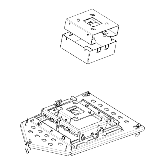
- Page 6 Mounting the Assembly Necessary Tools 1. Torx screw driver for M3 screw 2. Hexagonal driver (n° 6) 3. Ring spanner 12-13mm 4. Side spanner 12-13mm 5. Cross head screw driver for M8 screw Centering the ceiling mount Mark the position on the ceiling hole. Since the center of the lens does not coincide with the center of the projector, the center of the lens has been marked on the ceiling mount.
- Page 7 Mounting the Assembly The fixation can be done with standard M8 bolt (not supplied)
- Page 8 Projector preparation 1. Turn the projector to its back and remove the Feet assembly. Unscrew 3 Plastic feet and remove their Allen head M10 screws. Discard 3 plastic feet r852944 and x head M10 screw. R852944, R852945 & A566050 M10 SCREW, &...
- Page 9 Lift and slide the projector assembly into the Ceiling mount. The projector will be located precisely into the ceiling mount base plate after the tightening of 3 M 8 flange Nuts (b360623). Slide Lift 4. Route the Signal cables and Power cord into the cable saddles. 5.
- Page 10 Adjustments Following adjustment can be done in random order. Shift parallel to screen Up/down B 4no’s (2 in opposite side) Rotate around central Axis ±3° 1. Shift parallel to the screen Loosen the 2 bolts A and move the projector till the projector is aligned. Tighten these 2 bolts to secure the position.
- Page 11 Rotate around vertical axis ±5° Rotate around central Axis ±3°...
- Page 12 3. Rotate around central Vertical axis Loosen the 4 bolts E . Rotate/adjust the projector clockwise or anti clockwise. Tighten the 4 bolts E to secure the position. 4. Rotate around central Horizontal axis Loosen the 4 bolts F . Adjust the motion precisely by moving bolt G clockwise or anti clockwise.
- Page 13 Mounting the bar with Cable Cover assembly Unscrew the 2 bolts J and slide out the upper part of the Bar. Pass the cable cover into the upper part of the Bar Slide the horizontal shift plate R 826743 into the lower part of the Bar. Fix with 4 M8 bolt K.
- Page 14 Routing the Cables a. RGBHV cable preparation: With the help of PVC tape arrange the connectors in series. Pass the Signal cables and Power cord into cable guide R826761 b. Pass the Signal cables into the IQ bar assembly from top side. Take out the BNC connector (in case of a 5 BNC cable) one by one from bottom side.
- Page 15 c. Pass the Power cord and the other cables (if any) one by one. d. Pass all the cables one by one from cable guide R 826745 and fix the cable guide on to the horizontal shift plate using 2 M3 Screws L. The cable routing through IQ bar is complete.
- Page 16 Hang on the IQ bar and cable routed assembly. Fix with 4 M8 bolt along with washer M. Mount the Ceiling mount assembly on to the horizontal shift plate by twisting and then lifting up. Fix the 2 M8 Bolt A. Route the Power cord to the back and Signal cables to the front.
- Page 17 There is also an option to route the cable from inside the Ceiling mount using cable ties and guiding holes on the Ceiling mount base as shown below. Cable Ties RGB cables Power cord & other cables Cable Tie Break the cable guide grooves on the cable cover as per the direction and location of the input cables and power cord at customer site/room.
- Page 18 9. The adjustment procedure for the rotation around central vertical axis can also be done as explained below. Loosen the 4 M3 screws N of cable cover and slide it down word. Loosen the 4 bolts O. Rotate /adjust the projector clockwise or anti clockwise.
Need help?
Do you have a question about the R 9849999 and is the answer not in the manual?
Questions and answers