
Related Manuals for Barco R9841810


Summary of Contents for Barco R9841810
- Page 1 ARCO ROJECTION EPLACEMENT R9841810 NSTALLATION MANUAL For SLM projectors 08012003 R5976544/00...
- Page 2 Barco nv Events Noordlaan 5, B-8520 Kuurne Phone: +32 56.36.89.70 Fax: +32 56.36.88.24 E-mail: events@barco.com Visit us at the web: www.barco.com Printed in Belgium...
-
Page 3: Safety Warnings
1.2 Product care Installation Kit The Kit R9841810 - Lamp 2100W - is designed for use ONLY with the BARCO SLM 10 series projectors. Replacement parts When replacement parts are required, be sure the service technician has used original BARCO replacement parts or authorized replacement parts which have the same characteristics as the BARCO original part. - Page 4 1. Safety Warnings R5976544 LAMP REPLACEMENT KIT 08012003...
-
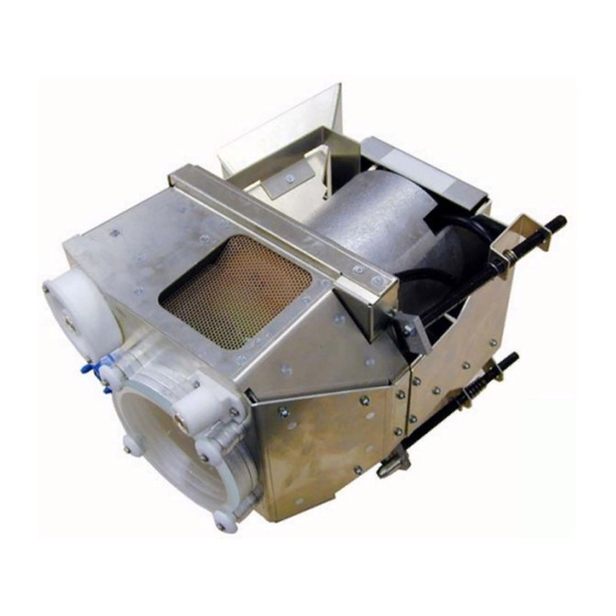
Page 5: Content Of The Kit
2. Introduction 2. INTRODUCTION 2.1 Content of the kit Content of the kit The kit contains a XENON 2200W projection Lamp mounted in a housing together with the reflector. The 3 lamp fixation spacers (with external thread on top) are fixed to the lamp casing frame by a nut M5 (C). Image 2-1 Part number Description... - Page 6 2. Introduction R5976544 LAMP REPLACEMENT KIT 08012003...
- Page 7 3. Removing the old lamp 3. REMOVING THE OLD LAMP 3.1 Access to the Lamp Unit. What has to be done To access the lamp casing, a side panel has to be removed. Necessary tools A flatblade screwdriver of 5 mm Removing the side panel 1.
-
Page 8: Removing The Lamp Unit
3. Removing the old lamp 3.2 Removing the Lamp Unit. What has to be done The lamp unit has to be slid out of the projector frame. Necessary tools Flatblade screwdriver of 5mm or Nutdriver of 8mm. Sliding out the lamp unit 1. - Page 9 4. Inserting the new lamp 4. INSERTING THE NEW LAMP 4.1 Installation of the new Lamp Unit. What has to be done First remove the lock nut on each spacer screw and next slide the lamp unit into the projector frame. Necessary tools Flatblade screwdriver of 5mm or Nut driver 8mm Installing the lamp unit...
- Page 10 4. Inserting the new lamp Image 4-2 Inserting the lamp Image 4-3 Securing the lamp 4.2 Optical Alignment of the lamp What had to be done Optical alignment of the lamp console consists of the following adjustments: • Lamp move forward/backward (Z-axis): adjustment for maximum light on the screen. •...
- Page 11 4. Inserting the new lamp Image 4-4 Optical alignment of the lamp What has to be done after operating the lamp After the lamp has been operated for many run times, a decrease of light output will be observed. An optical realignment of the lamp to the z-axis will compensate the decrease in light output.
-
Page 12: Reinstalling The Side Panel
4. Inserting the new lamp Image 4-5 Adjusting the Z-axis 4.3 Reinstalling the Side Panel What has to be done After the new lamp unit has been installed, the side panel has to be remounted. Necessary tools A flatblade screwdriver of 5 mm Reinstalling the side panel 1. - Page 13 4. Inserting the new lamp Image 4-6 Mounting the side cover Image 4-7 Closing the side cover Image 4-8 Locking the side cover R5976544 LAMP REPLACEMENT KIT 08012003...
Need help?
Do you have a question about the R9841810 and is the answer not in the manual?
Questions and answers