Fluke 117 User Manual
True-rms multimeters
Hide thumbs
Also See for 117:
- User manual ,
- Specifications (2 pages) ,
- Calibration information manual (26 pages)

Related Manuals for Fluke 117


Summary of Contents for Fluke 117
- Page 1 ® 114, 115, and 117 True-rms Multimeters Users Manual PN 2572573 July 2006, Rev. 1, 2/07 © 2006, 2007 Fluke Corporation, All rights reserved. Printed in China All product names are trademarks of their respective companies.
- Page 2 LIMITED WARRANTY AND LIMITATION OF LIABILITY This Fluke product will be free from defects in material and workmanship for three years from the date of purchase. This warranty does not cover fuses, disposable bat- teries, or damage from accident, neglect, misuse, alteration, contamination, or abnor- mal conditions of operation or handling.
- Page 3 True-rms Multimeters Introduction Unsafe Voltage The Fluke Model 114, Model 115, and Model 117 are To alert you to the presence of a potentially hazardous voltage, the Y symbol is displayed when battery-powered, true-rms multimeters (hereafter "the Meter") with a 6000-count display and a bar graph. This the Meter measures a voltage 30 V or a voltage manual applies to all three models.
- Page 4 114, 115, and 117 Users Manual Safety Information A "XWWarning" statement identifies hazardous conditions and actions that could cause bodily harm or death. A "WCaution" statement identifies conditions and actions that could damage the Meter or the equipment under test. To avoid possible electric shock or personal injury, follow these guidelines: Use the Meter only as specified in this manual or the protection provided by the Meter might be impaired.
- Page 5 Double Insulated Hazardous voltage Important Information; Refer to manual Battery (Low battery when shown on the Earth ground display.) Do not dispose of this product as unsorted AC and DC municipal waste. Contact Fluke or a qualified recycler for disposal.
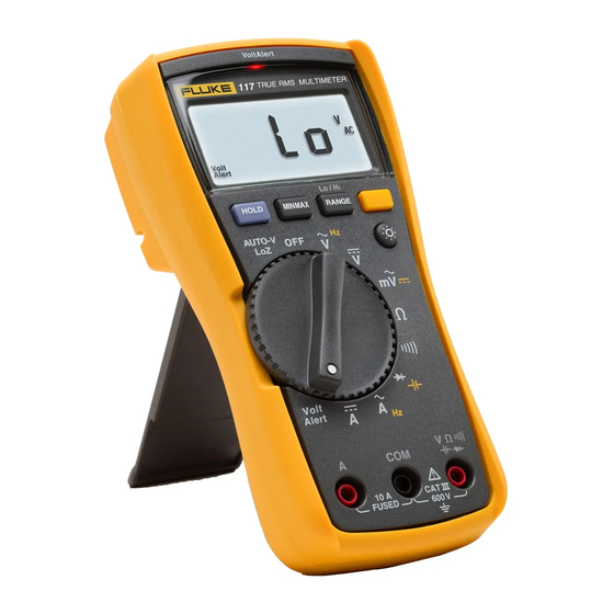
- Page 6 114, 115, and 117 Users Manual Display VoltAlert edy02f.eps Symbol Meaning Model The Meter is in the VoltAlert™ non-contact voltage detect mode. The Meter function is set to Continuity. 114, 115, & 117 The Meter function is set to Diode Test 115 &...
- Page 7 True-rms Multimeters Display Display hold enabled. Display freezes present reading. 114, 115, & 117 MIN MAX AVG mode enabled. 114, 115, & 117 Maximum, minimum, average or present reading displayed (Red LED) Voltage presence through the non-contact VoltAlert sensor The Meter is measuring voltage or capacitance with a low input 114, 115 &...
-
Page 8: Terminals
114, 115, and 117 Users Manual Terminals 10 A FUSED edy01f.eps Description Model Input terminal for measuring ac and dc current to 10 A. 115 & 117 Common (return) terminal for all measurements. 114, 115, & 117 Input terminal for measuring voltage, continuity, resistance, capacitance, 114, 115, &... -
Page 9: Rotary Switch Positions
True-rms Multimeters Rotary Switch Positions Rotary Switch Positions Switch Measurement Function Model Position Automatically selects ac or dc volts based on the sensed input with a low 114 & 117 impedance input. AC voltage from 0.06 to 600 V. 114, 115 & 117 Frequency from 5 Hz to 50 kHz. - Page 10 114, 115, and 117 Users Manual Battery Saver ("Sleep Mode") Display HOLD XWWarning The Meter automatically enters "Sleep mode" and blanks the display if there is no function change, range change, or To avoid electric shock, when Display button press for 20 minutes. Pressing any button or HOLD is activated, be aware that the turning the rotary switch awakens the Meter.
- Page 11 True-rms Multimeters Power-Up Options When you turn the Meter on, it defaults to Autorange and Button Power-Up Options Auto is displayed. 1. To enter the Manual Range mode, press Turns on all display segments. Manual is displayed. Disables beeper. bEEP is displayed when 2.
- Page 12 114, 115, and 117 Users Manual Measuring Resistance Testing for Continuity edy06f.eps Note edy04f.eps XWWarning The continuity function works best as a fast, To avoid electric shock, injury, or convenient method to check for opens and damage to the Meter, disconnect shorts.
- Page 13 True-rms Multimeters Making Basic Measurements This function also sets the Meter’s input impedance to Measuring AC and DC Voltage approximately 3 k to reduce the possibility of false Volts AC Volts DC readings due to ghost voltages. Measuring AC and DC Millivolts Millivolts AC Millivolts DC edy03f.eps...
- Page 14 114, 115, and 117 Users Manual Measuring AC or DC Current (115 & 117) XWWarning To avoid personal injury or damage to the Meter: Never attempt to make an in-circuit current measurement when the open- circuit potential to earth is 600 V.
- Page 15 Meter. Make sure the Meter has the correct function selected, AC or DC, for your current probe. Refer to a Fluke catalog or contact your local Fluke representative for compatible current clamps. edy05f.eps...
- Page 16 114, 115, and 117 Users Manual Press g to turn the frequency measurement function Measuring Frequency (115 & 117 only) on and off. Frequency works with ac functions only. XWWarning In frequency, the bar graph and range annunciator indicate To avoid electrical shock, disregard the bar the ac voltage or current present.
-
Page 17: Making Basic Measurements
True-rms Multimeters Making Basic Measurements To detect the presence of ac voltage, place the top of the Testing Diodes (115 & 117) Meter close to a conductor. The Meter gives an audible as Good Diode Good Diode well as visual indication when voltage is detected. There are two sensitivity settings. - Page 18 114, 115, and 117 Users Manual Using the Bargraph Testing the Fuse (115 & 117 only) The bar graph is like the needle on an analog meter. It has Test fuse as shown below. an overload indicator (>) to the right and a polarity indicator (+)to the left.
- Page 19 True-rms Multimeters Maintenance Maintenance Maintenance of the Meter consists of battery and fuse replacement, as well as case cleaning. Replacing the Battery and Fuse XWWarning To avoid shock, injury, or damage to the Meter: Remove test leads from the Meter before opening the case or battery door.
- Page 20 5. Remove the fuse from its holder and replace it with an 11 A, 1000 V, FAST fuse having a minimum interrupt rating of 17,000 A. Use only Fluke PN 803293. 6. To re-assemble the Meter, first attach the case bottom to the case top, then install the two screws.
- Page 21 Surge Protection ............. 6 kV peak per IEC 61010-1 600V CAT III, Pollution Degree 2 W Fuse for A input (115 & 117 only): ....11 A, 1000 V FAST 17 kA Fuse (Fluke PN 803293) Display ..............Digital: 6,000 counts, updates 4/sec Bar Graph: 33 segments, updates 32/sec Temperature.............
- Page 22 114, 115, and 117 Users Manual Certifications ............UL, , CSA, TÜV, N10140), VDE IP Rating (dust and water protection) IP42 ......Table 1. Accuracy Specifications Accuracy Function Range Resolution Model ([% of Reading] + [Counts]) 114, DC millivolts 600.0 mV 0.1 mV 0.5 % + 2 115, 117...
- Page 23 True-rms Multimeters General Specifications Table 1 Accuracy Specifications (cont.) Accuracy Function Range Resolution Model ([% of Reading] + [Counts]) Beeper on < 20 , off > 250 114, 115, Continuity detects opens or shorts of 500 s or longer. 600.0 0.9 % + 2 6.000 k 0.001 k...
- Page 24 114, 115, and 117 Users Manual Table 1 Accuracy Specifications (cont.) Accuracy Function Range Resolution Model ([% of Reading] + [Counts]) 6.000 A 0.001 A AC Amps True- 10.00 A 0.01 A 1.5 % + 3 115, 117 20 A for 30 seconds max., (45 Hz to 500 Hz) 10 minutes rest min.
- Page 25 True-rms Multimeters General Specifications Table 2. Input Characteristics Input Impedance Common Mode Rejection Ratio Normal Mode Function (Nominal) (1 k Unbalanced) Rejection Volts AC >5 M <100 pF >60 dB at dc, 50 or 60 Hz >10 M <100 pF >100 dB at dc, 50 or 60 Hz >60 dB at 50 or 60 Volts DC...
- Page 26 114, 115, and 117 Users Manual...
Need help?
Do you have a question about the 117 and is the answer not in the manual?
Questions and answers