Fluke 110 User Manual
True-rms multimeter
Hide thumbs
Also See for 110:
- User manual ,
- Calibration information manual (26 pages) ,
- User manual (66 pages)
Table of Contents
Advertisement
Advertisement
Table of Contents

Related Manuals for Fluke 110


Summary of Contents for Fluke 110
- Page 1 110/113/114/115/117 True-rms Multimeter Users Manual (Simplifed hinese) (Simplifed hinese) March 2020 © 2020 Fluke Corporation. All rights reserved. Specifications are subject to change without notice. All product names are trademarks of their respective companies.
- Page 2 LIMITED WARRANTY AND LIMITATION OF LIABILITY This Fluke product will be free from defects in material and workmanship for three years from the date of purchase. This warranty does not cover fuses, disposable batteries, or damage from accident, neglect, misuse, alteration, contamination, or abnormal conditions of operation or handling.
-
Page 3: Table Of Contents
Measuring AC and DC Millivolts (110, 114, 115, 117)........ Measuring AC or DC Current (115, 117) ............ Measuring Current above 10 Amps (110, 114, 115, 117) ......Measuring Capacitance (113, 115, 117) ............ 10 Measuring Frequency (115, 117) ............... 10 Detecting AC Voltage Presence (117)............ - Page 4 110/113/114/115/117 Users Manual...
-
Page 5: Introduction
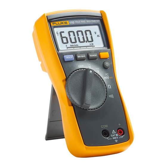
Introduction The Fluke Model 110, Model 113, Model 114, Model 115, and Model 117 (the Meter or Product) are battery- powered, true-rms multimeters with a 6000-count display and a bar graph. This manual applies to all models. All figures show the Model 117 unless indicated. -
Page 6: Product Familiarization
110/113/114/115/117 Users Manual Product Familiarization The manual explains features for multiple models. Because models have different features, not all of the information in the manual may apply to your Meter. Use Table to identify the features of your Meter. Features Table is a list of the features for each Meter. -
Page 7: Display
Model The Meter is in the VoltAlert™ non-contact voltage detect mode. The Meter function is set to Continuity. 110, 113, 114, 115, 117 The Meter function is set to Diode Test 113, 115, 117 Input is a negative value. -
Page 8: Terminals
The Meter is in the Auto Volts function. 114, 117 Auto Autoranging. The Meter selects the range for best resolution. 110, 113, 114, 115, 117 Manual Manual ranging. User sets the Meter’s range. 110, 113, 114, 115, 117 Bar graph polarity 110, 113, 114, 115, 117 ... -
Page 9: Error Messages
True-rms Multimeter Product Familiarization Error Messages Table is a list of error messages for the Meter. Table 4. Error Messages Error Messages Battery must be replaced before the Meter will operate. bAtt Calibration required. Meter calibration is required before the Meter will operate. CAL Err Internal error. -
Page 10: Display Hold
110/113/114/115/117 Users Manual Display HOLD XW Warning To avoid electric shock, when Display HOLD is activated, be aware that the display will not change when you apply a different voltage. In the Display HOLD mode, the Meter freezes the display. -
Page 11: Making Basic Measurements
XW Warning To avoid electric shock, injury, or damage to the Meter, disconnect circuit power and discharge all high-voltage capacitors before testing resistance, continuity, diodes, or capacitance. Measuring Resistance 110, 114, 115, 117 600 kΩ 6 kΩ 60 kΩ 600 kΩ... -
Page 12: Measuring Ac And Dc Voltage
This function also sets the Meter’s input impedance to approximately 3 kΩ to reduce the possibility of false readings due to ghost voltages. Measuring AC and DC Millivolts (110, 114, 115, 117) With the function switch in the l position, the Meter measures ac plus dc millivolts. Press g to set the Meter to dc millivolts. -
Page 13: Measuring Ac Or Dc Current (115, 117)
Meter. Make sure the Meter has the correct function selected, AC or DC, for your current probe. Refer to a Fluke catalog or contact your local Fluke representative for compatible current clamps. -
Page 14: Measuring Capacitance (113, 115, 117)
110/113/114/115/117 Users Manual Measuring Capacitance (113, 115, 117) 115,117 AC for AC Voltage AC for AC Voltage DC for DC Voltage DC for DC Voltage 60 V 600 V RANGE Measuring Frequency (115, 117) XW Warning To avoid electrical shock, disregard the bar graph for frequencies >1 kHz. If the frequency of the measured signal is >1 kHz, the bar graph and Z are unspecified. -
Page 15: Detecting Ac Voltage Presence (117)
True-rms Multimeter Product Familiarization Detecting AC Voltage Presence (117) To detect the presence of ac voltage, place the top of the Meter close to a conductor. The Meter gives an audible as well as visual indication when voltage is detected. The sensitivity settings are: •... -
Page 16: Testing Diodes (113, 115, 117)
110/113/114/115/117 Users Manual Testing Diodes (113, 115, 117) 115, 117 Good Diode Good Diode Good Diode Good Diode Good Diode Good Diode Single Beep Reverse Bias Forward Bias Reverse Bias Forward Bias Reverse Bias Forward Bias Bad Diode Bad Diode... -
Page 17: Maintenance
True-rms Multimeter Maintenance Maintenance Maintenance of the Meter consists of battery and fuse replacement, as well as case cleaning. Testing the Fuse (115, 117) Test fuse as shown in Figure 1. <.5 Figure 1. Test the Fuse Replacing the Battery and Fuse XW Warning To avoid shock, injury, or damage to the Meter: •... -
Page 18: Cleaning
5. Remove the fuse from its holder and replace it with an 11 A, 1000 V, FAST fuse having a minimum interrupt rating of 17,000 A. Use only Fluke PN 803293. 6. To re-assemble the Meter, first attach the case bottom to the case top, then install the two screws. Finally, insert the Meter into its holster. -
Page 19: Specifications
Relative Humidity............95 % to 30 °C, 75 % to 40 °C, 45 % to 50 °C Battery................. IEC 6LR61 Battery Life 113................Alkaline: 300 hours typical, without backlight 110, 114, 115, 117............ Alkaline: 400 hours typical, without backlight Safety ................IEC 61010-1: Pollution Degree 2 IEC 61010-2-033 113................Measurement CAT IV 600 V 110, 114.............. - Page 20 Resolution Model ± ([% of Reading] + [Counts]) DC Millivolts 600.0 mV 0.1 mV 0.5 % + 2 110, 114, 115, 117 6.000 V 0.001 V DC Volts 60.00 V 0.01 V 0.5 % + 2 110, 114, 115, 117 600.0 V...
- Page 21 ≤3 at 4000 counts, decreasing linearly to 1.5 at full scale. 113 only: After measuring voltage, a wait time of 1 minute is required to maintain accuracy of ohms, capacitance, diode test, and continuity. Table 7. Input Characteristics (110, 114, 115, 117) Common Mode Rejection Ratio...
- Page 22 110/113/114/115/117 Users Manual Table 8. Input Characteristics (113) Function Input Impedance (Nominal) Common Mode Rejection Ratio k CHEK ~3 kΩ <300 pF >60 dB at dc, 50 or 60 Hz Open Circuit Test Voltage Full Scale Voltage Ohms <2.7 V dc <0.7 V dc...
Need help?
Do you have a question about the 110 and is the answer not in the manual?
Questions and answers