TP-Link TL-SG1008P User Manual
8-port gigabit desktop switch with 4-port poe
Hide thumbs
Also See for TL-SG1008P:
- Installation manual (3 pages) ,
- Mounting manual (5 pages) ,
- Wall mounting manual (3 pages)

Related Manuals for TP-Link TL-SG1008P


Summary of Contents for TP-Link TL-SG1008P
-
Page 1: User Guide
User Guide TL-SG1008P 8-Port Gigabit Desktop Switch with 4-Port PoE Rev 1.0.0 7106504137... - Page 3 No part of the specifications may be reproduced in any form or by any means or used to make any derivative such as translation, transformation, or adaptation without permission from TP-LINK TECHNOLOGIES CO., LTD. Copyright © 2012 TP-LINK TECHNO- LOGIES CO., LTD. All rights reserved. http://www.tp-link.com...
-
Page 4: Fcc Statement
FCC STATEMENT This equipment has been tested and found to comply with the limits for a Class A digital device, pursuant to part 15 of the FCC Rules. These limits are designed to provide reasonable protection against harmful interference when the equipment is operated in a commercial environment. -
Page 5: Ce Mark Warning
Any changes or modifications not expressly approved by the party responsible for compliance could void the user’s authority to operate the equipment. CE Mark Warning This is a class A product. In a domestic environment, this product may cause radio interference, in which case the user may be required to take adequate measures. -
Page 6: Table Of Contents
CONTENT ............Package Contents ......Chapter 1. Introduction of the Product Overview of the Product ........2 Convention ............3 Features..............3 ..........Chapter 2. Installation Mounting the Switch on a Desk......4 Power On ............... 4 ....Chapter 3. Identifying External Components Front Panel ............ -
Page 7: Package Contents
Package Contents The following items should be found in your box: ¾ One TL-SG1008P 8-Port Gigabit Desktop Switch with 4-Port ¾ One DC Power Adapter ¾ Four rubber cushions to be used under the Switch ¾ This User Guide Note Make sure that the box contains the above items. -
Page 8: Chapter 1. Introduction Of The Product
Chapter 1. Introduction of the Product Thank you for choosing the TL-SG1008P 8-Port Gigabit Desktop Switch with 4-Port PoE. 1.1 Overview of the Product The TL-SG1008P 8-Port Gigabit Desktop Switch with 4-Port PoE provides the seamless network connection, which integrates 1000Mbps Gigabit Ethernet, 100Mbps Fast Ethernet and 10Mbps Ethernet network capabilities. -
Page 9: Convention
¾ Supports PoE IEEE802.3af compliant PDs ¾ Supports IEEE802.3x flow control for Full-duplex Mode and backpressure for Half-duplex Mode ¾ 8K entry MAC address table of the TL-SG1008P with auto- learning and auto-aging ¾ LED indicators for monitoring Power, Link/Act, Speed and PoE Status ¾... -
Page 10: Chapter 2. Installation
2) Make sure the power is off before unplugging the power adapter. 2.2 Power On The TL-SG1008P Switch can be used with DC power supply. Powering on the Switch, it will automatically initialize and its LED indicators will respond as follows:... -
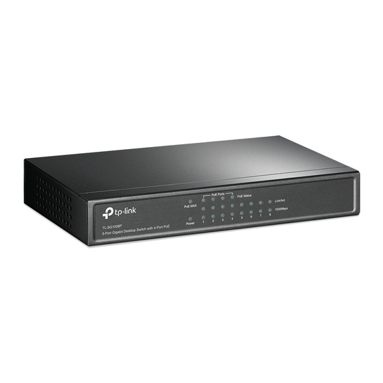
Page 11: Chapter 3. Identifying External Components
Identifying External Components This Chapter describes the front panel, rear panel and LED indi- cators of the Switch. 3.1 Front Panel Figure 3-1 TL-SG1008P Switch Front Panel The Switch’s LEDs are located on the front panel. Name Status Indication The Switch is powered on. - Page 12 Name Status Indication There is a PoE PD connected to the port, which supply power successfully. (green) Flashing The PoE power circuit may be in short or the PoE ports power current may be overloaded. (green) (ports1~4) No PD is connected to the corresponding port, or no power is supplied according to the power limits of the port.
-
Page 13: Rear Panel
Figure 3-2 TL-SG1008P Switch Rear Panel The following parts are located on the rear panel: ¾ Power (48V): 48V indicates the input voltage of the power adapter provided with this TL-SG1008P Switch. The Power socket is where you will connect the power adapter. - Page 14 LEDs on the front panel. ¾ Ethernet Ports (1-8): Besides the 4 PoE ports, the TL-SG1008P Switch is also equipped with the other four 10/100/1000Mbps Auto-Negotiation RJ45 ports without PoE function. Once the network devices are connected to these...
-
Page 15: Appendix A: Specifications
Appendix A: Specifications General IEEE802.3, IEEE802.3u, IEEE802.3ab Standard IEEE802.3x, IEEE802.3af Protocol CSMA/CD Ethernet: 10Mbps (Half Duplex) 20Mbps (Full Duplex) Data Transfer Rate Fast Ethernet: 100Mbps (Half Duplex) 200Mbps (Full Duplex) Gigabit Ethernet: 2000Mbps (Full Duplex) 10Base-T: UTP category 3, 4, 5 cable (maximum 100m) EIA/TIA-568 100 STP (maximum 100m) 100Base-TX: Network Media(Cable) - Page 16 MAC Address Learning Automatically learning, automatically aging 10Base-T: 14880pps/Port Frame Filter Rate 100Base-Tx: 148800pps/Port 1000Base-T: 1488000pps/Port 10Base-T: 14880pps/Port Frame Forward Rate 100Base-Tx: 148800pps/Port 1000Base-T: 1488000pps/Port Environmental and Physical 5.8 Watts (max. no PD connected) Power Consumption 58.8 Watts (max. with 53W PD connected) Operating Temperature 0 ~40 (32 ~104 )
Need help?
Do you have a question about the TL-SG1008P and is the answer not in the manual?
Questions and answers