HP Elite 7000 - Microtower PC Maintenance And Service Manual
Maintenance & service guide: hp elite 7000 mt series pcs
Hide thumbs
Also See for Elite 7000 - Microtower PC:
- Troubleshooting manual (49 pages) ,
- Disassembly instructions manual (15 pages) ,
- Setup manual (11 pages)
Table of Contents
Advertisement
Quick Links
Advertisement
Table of Contents

Related Manuals for HP Elite 7000 - Microtower PC


Summary of Contents for HP Elite 7000 - Microtower PC
- Page 1 Maintenance & Service Guide HP Elite 7000 MT Series PCs...
- Page 2 © Copyright 2009 Hewlett-Packard Development Company, L.P. The information contained herein is subject to change without notice. Microsoft and Windows are trademarks of Microsoft Corporation in the U.S. and other countries. The only warranties for HP products and services are set forth in the express warranty statements accompanying such products and services.
-
Page 3: About This Book
About This Book WARNING! Text set off in this manner indicates that failure to follow directions could result in bodily harm or loss of life. CAUTION: Text set off in this manner indicates that failure to follow directions could result in damage to equipment or loss of information. - Page 4 About This Book...
-
Page 5: Table Of Contents
Computer Setup—Boot ...................... 11 Computer Setup—Exit ....................... 12 Recovering the Configuration Settings ....................12 4 Computer Diagnostic Features Hewlett-Packard Vision Diagnostics ....................13 Accessing HP Vision Diagnostics ..................13 Survey Tab ........................14 Test Tab ..........................14 Status Tab ......................... 15 History Tab ........................ - Page 6 Saving and Printing Information in HP Vision Diagnostics ..........17 Downloading the Latest Version of HP Vision Diagnostics ..........17 Protecting the Software ........................17 5 Serial ATA (SATA) Drive Guidelines and Features SATA Hard Drives ..........................18 SATA Hard Drive Cables ........................18 SATA Data Cable ......................
- Page 7 Populating DIMM Sockets ....................34 Installing Memory Modules ....................35 Expansion Cards ..........................37 Cable Management ........................... 41 Cable Connections ......................42 Drives ..............................43 Drive Positions ........................43 Installing Additional Drives ....................44 System Board Drive Connections ..............45 Removing an Optical Drive ................
- Page 8 Appendix B Power Cord Set Requirements General Requirements ........................78 Japanese Power Cord Requirements ....................78 Country-Specific Requirements ......................79 Appendix C Troubleshooting Without Diagnostics Safety and Comfort ..........................80 Before You Call for Technical Support ....................80 Helpful Hints ............................81 Solving General Problems ........................
-
Page 9: Installing And Customizing The Software
Installing and Customizing the Software If your computer was not shipped with a Microsoft operating system, some portions of this documentation do not apply. Additional information is available in online help after you install the operating system. NOTE: If the computer was shipped with Windows Vista or Windows 7 loaded, you will be prompted to register the computer with HP Total Care before installing the operating system. -
Page 10: Installing The Operating System
Installing the Operating System The first time you turn on the computer, the operating system is installed automatically. This process takes about 5 to 10 minutes, depending on which operating system is being installed. Carefully read and follow the instructions on the screen to complete the installation. CAUTION: Once the automatic installation has begun, DO NOT TURN OFF THE COMPUTER UNTIL THE PROCESS IS COMPLETE. -
Page 11: Accessing Disk Image (Iso) Files
Accessing Disk Image (ISO) Files There are disk image files (ISO files) included on your PC that contain the installation software for additional software. These CD image files are located in the folder C:\SWSetup\ISOs. Each .iso file can be burned to CD media to create an installation CD. It is recommended that these disks be created and the software installed in order to get the most from your PC. -
Page 12: Product Features
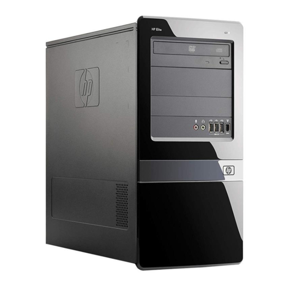
Product Features Standard Configuration Features The Elite 7000 MT Series PC features may vary depending on the model. For a complete listing of the hardware and software installed in the computer, run the diagnostic utility (included on some computer models only). Instructions for using the utility are provided in the Troubleshooting Guide. Figure 2-1 HP Elite 7000 MT Series PC NOTE:... -
Page 13: Front Panel Components
Front Panel Components Drive configuration may vary by model. Figure 2-2 Front Panel Components Table 2-1 Front Panel Components 5.25-inch Optical Drives Hard Drive Activity Light Optical Drive Activity Lights Optical Drive Eject Buttons 3.5-inch Media Card Reader (optional) Headphone Connector Microphone Connector USB (Universal Serial Bus) 2.0 Ports Dual-State Power Button... -
Page 14: Media Card Reader Components
Media Card Reader Components The media card reader is an optional device available on some models only. Refer to the following illustration and table to identify the media card reader components. Figure 2-3 Media Card Reader Components Table 2-2 Media Card Reader Components Slot Media ●... -
Page 15: Rear Panel Components
Rear Panel Components Figure 2-4 Rear Panel Components Table 2-3 Rear Panel Components Power Cord Connector Sony/Philips Digital Interconnect Format (S/PDIF) Connector (green) Voltage Select Switch Line-Out Connector for powered audio devices (green) Line-In Audio Connector (blue) Microphone Connector (pink) Rear Center Channel/Subwoofer Audio Surround Side Channel Audio Connector (orange) -
Page 16: Computer Setup (F10) Utility
Computer Setup (F10) Utility Computer Setup (F10) Utilities Use Computer Setup (F10) Utility to do the following: ● Change factory default settings. ● Set the system date and time. ● Set, view, change, or verify the system configuration, including settings for graphics, audio, storage, communications, and input devices. -
Page 17: Computer Setup-Main
Use the arrow keys to select the appropriate heading, then press Enter. Use the arrow (up and down) keys to select the option you want, then press Enter. To return to the previous screen, press Esc. CAUTION: Do NOT turn the computer power OFF while the ROM is saving the Computer Setup (F10) changes because the CMOS could become corrupted. -
Page 18: Computer Setup-Advanced
Computer Setup—Advanced NOTE: Support for specific Computer Setup options may vary depending on the hardware configuration. WARNING! Setting items on this menu to incorrect values may cause your system to malfunction. Table 3-2 Computer Setup—Advanced Option Description CPU Type (view only) CPU Speed (view only) Cache RAM(L2) -
Page 19: Computer Setup-Power
Table 3-2 Computer Setup—Advanced (continued) F11:Recovery Allows you to enable/disable the option to press the key to access the Recovery menu during computer startup. F12:Boot from LAN Allows you to enable/disable the option to press the key to access the Boot from LAN option during computer startup. -
Page 20: Computer Setup-Exit
Table 3-4 Computer Setup—Boot (continued) CD-ROM Group Boot Specifies boot device priority within CD/DVD drives. Priority Hard Drive Group Boot Specifies boot device priority within hard drives. Priority Network Group Boot Specifies boot device priority within bootable network devices. Priority Computer Setup—Exit NOTE: Support for specific Computer Setup options may vary depending on the hardware... -
Page 21: Computer Diagnostic Features
HP Vision Diagnostics is included on CD with some computer models only. The Hewlett-Packard Vision Diagnostics utility allows you to view information about the hardware configuration of the computer and perform hardware diagnostic tests on the subsystems of the computer. -
Page 22: Survey Tab
NOTE: If the system does not boot to the CD in the optical drive or to the USB flash drive, you may need to change the boot order in the Computer Setup (F10) utility. Refer to the Computer Setup (F10) Utility Guide for more information. At the boot menu, select either the HP Vision Diagnostics utility to test the various hardware components in the computer or the HP Memory Test utility to test memory only. -
Page 23: Status Tab
The test status (running, waiting, passed, or failed) of each device being tested ● The overall test progress of all devices being tested ● The test progress for each device being tested ● The elapsed test times for each device being tested Hewlett-Packard Vision Diagnostics... -
Page 24: History Tab
You may also review the HP End User License Agreement (EULA), as well as the HP Vision Diagnostic application version information on this tab. The Vision Help section contains information on the major functions of Hewlett-Packard Vision Diagnostics. -
Page 25: Saving And Printing Information In Hp Vision Diagnostics
Select your specific computer model. Select your OS. Click the Diagnostic link. Click the Hewlett-Packard Vision Diagnostics link. Click the Download button. NOTE: The download includes instructions on how to create the bootable CD or the bootable USB flash drive. -
Page 26: Serial Ata (Sata) Drive Guidelines And Features
Serial ATA (SATA) Drive Guidelines and Features NOTE: HP only supports the use of SATA hard drives on these models of computer. No Parallel ATA (PATA) drives are supported. SATA Hard Drives Serial ATA Hard Drive Characteristics Number of pins/conductors in data cable Number of pins in power cable Maximum data cable length 39.37 in (100 cm) -
Page 27: Smart Ata Drives
SMART ATA Drives The Self Monitoring Analysis and Recording Technology (SMART) ATA drives for the HP Personal Computers have built-in drive failure prediction that warns the user or network administrator of an impending failure or crash of the hard drive. The SMART drive tracks fault prediction and failure indication parameters such as reallocated sector count, spin retry count, and calibration retry count. -
Page 28: Identifying The Chassis, Routine Care, And Disassembly Preparation
Identifying the Chassis, Routine Care, and Disassembly Preparation This chapter provides general service information for the computer. Adherence to the procedures and precautions described in this chapter is essential for proper service. CAUTION: When the computer is plugged into an AC power source, voltage is always applied to the system board. -
Page 29: Generating Static
Generating Static The following table shows that: ● Different activities generate different amounts of static electricity. ● Static electricity increases as humidity decreases. Relative Humidity Event Walking across carpet 7,500 V 15,000 V 35,000 V Walking across vinyl floor 3,000 V 5,000 V 12,000 V Motions of bench worker... -
Page 30: Personal Grounding Methods And Equipment
Personal Grounding Methods and Equipment Use the following equipment to prevent static electricity damage to equipment: ● Wrist straps are flexible straps with a maximum of one-megohm ± 10% resistance in the ground cords. To provide proper ground, a strap must be worn snug against bare skin. The ground cord must be connected and fit snugly into the banana plug connector on the grounding mat or workstation. -
Page 31: Operating Guidelines
● Field service kits ● Static awareness labels ● Wrist straps and footwear straps providing one-megohm +/- 10% resistance ● Material handling packages ● Conductive plastic bags ● Conductive plastic tubes ● Conductive tote boxes ● Opaque shielding bags ● Transparent metallized shielding bags ●... -
Page 32: Routine Care
Routine Care General Cleaning Safety Precautions Never use solvents or flammable solutions to clean the computer. Never immerse any parts in water or cleaning solutions; apply any liquids to a clean cloth and then use the cloth on the component. Always unplug the computer when cleaning with liquids or damp cloths. -
Page 33: Cleaning The Monitor
● If you remove a key, use a specially designed key puller to prevent damage to the keys. This tool is available through many electronic supply outlets. CAUTION: Never remove a wide leveled key (like the space bar) from the keyboard. If these keys are improperly removed or installed, the keyboard may not function properly. -
Page 34: Screws
● Diagnostics software ● HP tamper-resistant T-15 wrench (Smart Cover FailSafe Key, PN 166527-001) or HP tamper- resistant bits (Smart Cover FailSafe Key, PN 166527-002) Screws The screws used in the computer are not interchangeable. They may have standard or metric threads and may be of different lengths. -
Page 35: Lithium Coin Cell Battery
Lithium Coin Cell Battery The battery that comes with the computer provides power to the real-time clock and has a minimum lifetime of about three years. See the appropriate removal and replacement chapter for the chassis you are working on in this guide for instructions on the replacement procedures. -
Page 36: Removal And Replacement Procedures Microtower (Mt) Chassis
Removal and Replacement Procedures Microtower (MT) Chassis Adherence to the procedures and precautions described in this chapter is essential for proper service. After completing all necessary removal and replacement procedures, run the Diagnostics utility to verify that all components operate properly. NOTE: Not all features listed in this guide are available on all computers. -
Page 37: Preparation For Disassembly
Preparation for Disassembly Close any open software applications. Exit the operating system. Remove any diskette or compact disc from the computer. Turn off the computer and any peripheral devices that are connected to it. CAUTION: Turn off the computer before disconnecting any cables. CAUTION: Regardless of the power-on state, voltage is always present on the system board as long as the system is plugged into an active AC outlet. -
Page 38: Access Panel
Access Panel Prepare the computer for disassembly (Preparation for Disassembly on page 29). Remove the screw (1) that secures the access panel to the computer chassis. Slide the access panel back (2) about 1.3 cm (1/2 inch), then lift it off the unit. NOTE: You may want to lay the computer on its side to install internal parts. -
Page 39: Front Bezel
Front Bezel Prepare the computer for disassembly (Preparation for Disassembly on page 29). Remove the access panel (Access Panel on page 30). Press outward on the three latches on the right side of the bezel (1), then rotate the right side of the bezel off the chassis (2) followed by the left side. -
Page 40: Bezel Blanks
Bezel Blanks On some models, there are bezel blanks covering the 3.5-inch and 5.25-inch external drive bays that need to be removed before installing a drive. To remove a bezel blank: Follow the instructions described in Front Bezel on page Press the two retaining tabs towards the outer left edge of the bezel (1) and pull the bezel blank inwards to remove it (2). -
Page 41: Memory
Memory The computer comes with double data rate 3 synchronous dynamic random access memory (DDR3- SDRAM) dual inline memory modules (DIMMs). DDR3-SDRAM DIMMs The memory sockets on the system board can be populated with up to four industry-standard DIMMs. These memory sockets are populated with at least one preinstalled DIMM. To achieve the maximum memory support, you can populate the system board with up to 8 GB of memory configured in a high- performing dual channel mode. -
Page 42: Populating Dimm Sockets
Populating DIMM Sockets There are four DIMM sockets on the system board, with two sockets per channel. The sockets are labeled DIMM1, DIMM2, DIMM3, and DIMM4. Sockets DIMM2 and DIMM4 operate in memory channel A. Sockets DIMM1 and DIMM3 operate in memory channel B. Figure 7-5 DIMM Socket Locations Table 7-1... -
Page 43: Installing Memory Modules
balanced so that the largest amount of memory is spread between the two channels. If one channel will have more memory than the other, the larger amount should be assigned to Channel A. For example, if you are populating the sockets with one 2-GB DIMM, and three 1-GB DIMMs, Channel A should be populated with the 2-GB DIMM and one 1-GB DIMM, and Channel B should be populated with the two 1-GB DIMMs. - Page 44 Open both latches of the memory module socket (1), and insert the memory module into the socket (2). Figure 7-6 Installing a DIMM NOTE: A memory module can be installed in only one way. Match the notch on the module with the tab on the memory socket.
-
Page 45: Expansion Cards
Expansion Cards The computer has three PCI Express x1 expansion slots and one PCI Express x16 expansion slot. The expansion slots accommodate full-height or half-height expansion cards. Figure 7-7 Expansion Slot Locations Table 7-2 Expansion Slot Locations Item Description PCI Express x1 expansion slot PCI Express x1 expansion slot PCI Express x1 expansion slot PCI Express x16 expansion slot... - Page 46 On the rear of the computer, a slot cover lock secures the expansion card brackets in place. Remove the screw from the slot cover lock then slide the slot cover lock up to remove it from the chassis. Figure 7-8 Opening the Slot Cover Lock Before installing an expansion card, remove the expansion slot cover or the existing expansion card.
- Page 47 If you are removing a PCI Express x1 card, hold the card at each end and carefully rock it back and forth until the connectors pull free from the socket. Be sure not to scrape the card against the other components. Figure 7-10 Removing a PCI Express x1 Expansion Card If you are removing a PCI Express x16 card, pull the retention arm on the back of the expansion...
- Page 48 CAUTION: After removing an expansion card, you must replace it with a new card or expansion slot cover for proper cooling of internal components during operation. To install a new expansion card, hold the card just above the expansion socket on the system board then move the card toward the rear of the chassis so that the bottom of the bracket on the card slides into the small slot on the chassis.
-
Page 49: Cable Management
Connect external cables to the installed card, if needed. Connect internal cables to the system board, if needed. Reconfigure the computer, if necessary. Refer to the Computer Setup (F10) Utility Guide for instructions on using Computer Setup. Cable Management Always follow good cable management practices when working inside the computer. ●... -
Page 50: Cable Connections
Cable Connections System board connectors are color-coded to make it easier to find the proper connection. Connector Name Connector Color Description ATX1 White Power supply, 24-pin PWR1 White Power supply, 4-pin SYS_FAN1 Brown Chassis fan CPU_FAN1 White Heat sink fan JAUD1 Yellow Front I/O audio... -
Page 51: Drives
Drives The computer supports up to five drives that may be installed in various configurations. This section describes the procedure for replacing or upgrading the storage drives. A Torx T-15 screwdriver is needed to remove and install the guide screws on a drive. Drive Positions Figure 7-14 Drive Positions... -
Page 52: Installing Additional Drives
Installing Additional Drives When installing additional drives, follow these guidelines: ● The primary Serial ATA (SATA) hard drive must be connected to the dark blue primary SATA connector on the system board labeled SATA1. ● Connect the first SATA optical drive to the white SATA connector on the system board labeled SATA2. -
Page 53: System Board Drive Connections
CAUTION: To prevent loss of work and damage to the computer or drive: If you are inserting or removing a drive, shut down the operating system properly, turn off the computer, and unplug the power cord. Do not remove a drive while the computer is on or in standby mode. Before handling a drive, ensure that you are discharged of static electricity. -
Page 54: Removing An Optical Drive
Removing an Optical Drive CAUTION: All removable media should be taken out of a drive before removing the drive from the computer. To remove an optical drive: Prepare the computer for disassembly (Preparation for Disassembly on page 29). Remove the access panel (Access Panel on page 30). -
Page 55: Installing An Optical Drive Into The 5.25-Inch Drive Bay
NOTE: To install an optical drive, refer to Installing an Optical Drive into the 5.25-inch Drive Bay on page Installing an Optical Drive into the 5.25-inch Drive Bay To install an optional 5.25-inch optical drive: Prepare the computer for disassembly (Preparation for Disassembly on page 29). -
Page 56: Removing An External 3.5-Inch Drive
Connect the power cable (1) and data cable (2) to the rear of the optical drive. Figure 7-20 Connecting the Power and Data Cables Replace the front bezel and access panel. Reconnect the power cord and turn on the computer. Lock any security devices that were disengaged when the access panel was removed. -
Page 57: Installing A Drive Into The 3.5-Inch External Drive Bay
Disconnect the USB cable from the system board. Figure 7-21 Disconnecting the Media Card Reader Cable Remove the two retainer screws that secure the reader to the bay (1) then slide the reader forward and out of the bay (2). Figure 7-22 Removing a 3.5-inch Device (Media Card Reader Shown) NOTE:... - Page 58 Remove the front bezel (Front Bezel on page 31). If you are installing a media card reader in a bay covered by a bezel blank, remove the front bezel then remove the bezel blank. If you are adding a drive to an empty drive bay for the first time, you must remove the knockout plate from the bay.
-
Page 59: Removing An Internal 3.5-Inch Hard Drive
Removing an Internal 3.5-inch Hard Drive NOTE: Before you remove the old hard drive, be sure to back up the data from the old hard drive so that you can transfer the data to the new hard drive. Also, if you are replacing the primary hard drive, make sure you have created a Recovery Disc Set to restore the operating system, software drivers, and any software applications that were preinstalled on the computer. - Page 60 Lift the hard drive cage out of the chassis. Figure 7-26 Removing the Hard Drive Cage Disconnect the power cable (1) and data cable (2) from the back of the hard drive. Figure 7-27 Disconnecting the Hard Drive Cables Chapter 7 Removal and Replacement Procedures Microtower (MT) Chassis...
- Page 61 Remove the four screws that secure the hard disk drive to the hard drive cage (1), then slide the hard disk drive out of the hard drive cage (2). Figure 7-28 Removing the Hard Drive NOTE: To install an internal 3.5-inch hard drive, refer to Installing an Internal 3.5-inch Hard Drive on page Drives...
-
Page 62: Installing An Internal 3.5-Inch Hard Drive
Installing an Internal 3.5-inch Hard Drive Follow the steps in Removing an Internal 3.5-inch Hard Drive on page 51 to remove the hard drive cage and, if necessary, the existing hard drive. Slide the new drive into the hard drive cage (1), aligning the drive with the four screw holes on the cage. - Page 63 Connect the power cable (1) and data cable (2) to the back of the hard drive. Figure 7-30 Connecting the Hard Drive Cables CAUTION: Never crease or bend a SATA data cable tighter than a 30 mm (1.18 in) radius. A sharp bend can break the internal wires.
- Page 64 Attach the two screws that secure the hard drive cage to the chassis. Figure 7-32 Securing the Hard Drive Cage If installing a new drive, connect the opposite end of the data cable to the appropriate system board connector. NOTE: If your system has only one SATA hard drive, you must connect the hard drive data cable to the dark blue connector labeled SATA1 to avoid any hard drive performance problems.
-
Page 65: Front I/O And Usb Panel Housing Assembly
Front I/O and USB Panel Housing Assembly Prepare the computer for disassembly (Preparation for Disassembly on page 29). Remove the access panel (Access Panel on page Lay the computer on its side with the front facing toward you. Remove the front bezel (Front Bezel on page 31). -
Page 66: Power Switch/Led Assembly
Power Switch/LED Assembly Prepare the computer for disassembly (Preparation for Disassembly on page 29). Remove the access panel (Access Panel on page 30). Lay the computer on its side with the front facing toward you. Remove the front bezel (Front Bezel on page 31). -
Page 67: System Fan
System Fan Prepare the computer for disassembly (Preparation for Disassembly on page 29). Remove the access panel (Access Panel on page 30). Lay the computer on its side with the rear facing toward you. Disconnect the cable from the red/brown system board connector labeled SYS_FAN1. Remove the four Phillips screws that secure the fan to the chassis, rotate the top of the fan forward, and then remove the fan from the chassis. -
Page 68: Heat Sink Assembly
Heat sink assembly Prepare the computer for disassembly (Preparation for Disassembly on page 29). Remove the access panel (Access Panel on page 30). Lay the computer on its side with the rear facing toward you. Disconnect the heat sink fan control cable (1) from the white system board connector labeled CPU_FAN1. - Page 69 Carefully lift the processor from the socket (3). CAUTION: Do NOT handle the pins in the processor socket. These pins are very fragile and handling them could cause irreparable damage. Once pins are damaged it may be necessary to replace the system board. CAUTION: The heatsink must be installed within 24 hours of installing the processor to prevent damage to the processor’s solder connections.
-
Page 70: Power Supply
Power Supply WARNING! Voltage is always present on the system board when the computer is plugged into an active AC outlet. To avoid possible personal injury and damage to the equipment the power cord should be disconnected from the computer and/or the AC outlet before opening the computer. NOTE: When installing a new power supply, be sure to set the red switch to the setting (230 V or 115 V) appropriate for the country in which the computer is used. - Page 71 Inside of the unit, press the power supply release latch on the chassis base, and then lift up the rear of the power supply to disengage it from the chassis. Slide the power supply toward the front/bottom of the computer, then lift the power supply out of the computer.
-
Page 72: System Board
System Board When replacing the system board, be sure that the following components are removed from the defective system board and installed on the replacement system board: ● Memory modules ● Processor ● Expansion cards To remove the system board: Prepare the computer for disassembly (Preparation for Disassembly on page 29). - Page 73 Slide the system board toward the front of the chassis, and then lift it up and out of the chassis. NOTE: The system board in the computer may look slightly different from the one shown here. To install the system board, reverse the removal procedure. NOTE: When replacing the system board, you must also change the chassis serial number in the BIOS.
-
Page 74: Battery
Battery The battery that comes with your computer provides power to the real-time clock and has a lifetime of about three years. When replacing the battery, use a battery equivalent to the battery originally installed on the computer. The computer comes with a 3-volt lithium coin cell battery. NOTE: The lifetime of the lithium battery can be extended by plugging the computer into a live AC wall socket. -
Page 75: Type 1 Battery Holder
Type 1 Battery Holder Lift the battery out of its holder. Slide the replacement battery into position, positive side up. The battery holder automatically secures the battery in the proper position. Replace the computer access panel. Plug in the computer and turn on power to the computer. Reset the date and time, your passwords, and any special system setups, using Computer Setup. -
Page 76: Type 3 Battery Holder
Plug in the computer and turn on power to the computer. Reset the date and time, your passwords, and any special system setups, using Computer Setup. Refer to the Computer Setup (F10) Utility Guide. Type 3 Battery Holder Pull back on the clip (1) that holds the battery in place, then remove the battery (2). Insert the new battery and position the clip back in place. -
Page 77: Installing A Security Lock
Installing a Security Lock The security locks displayed below and on the following pages can be used to secure the computer. Cable Lock Figure 7-33 Installing a Cable Lock Padlock Figure 7-34 Installing a Padlock Installing a Security Lock... -
Page 78: Hp Business Pc Security Lock
HP Business PC Security Lock Fasten the security cable by looping it around a stationary object. Figure 7-35 Securing the Cable to a Fixed Object Thread the keyboard and mouse cables through the lock. Figure 7-36 Threading the Keyboard and Mouse Cables Chapter 7 Removal and Replacement Procedures Microtower (MT) Chassis... - Page 79 Screw the lock to the chassis using the screw provided. Figure 7-37 Attaching the Lock to the Chassis Insert the plug end of the security cable into the lock (1) and push the button in (2) to engage the lock. Use the key provided to disengage the lock. Figure 7-38 Engaging the Lock Installing a Security Lock...
-
Page 80: Appendix A Connector Pin Assignments
Connector Pin Assignments This appendix contains the pin assignments for many computer and workstation connectors. Some of these connectors may not be used on the product being serviced. Ethernet BNC Connector and Icon Signal Data Ground Connector and Icon Signal +5 VDC - Data + Data... -
Page 81: Headphone
Headphone Connector and Icon (1/8” miniphone) Signal 1 (Tip) Audio_left 1 2 3 2 (Ring) Power_Right 3 (Shield) Ground Line-in Audio Connector and Icon (1/8” miniphone) Signal 1 (Tip) Audio_In_Left 1 2 3 2 (Ring) Audio_In_Right 3 (Shield) Ground Line-out Audio Connector and Icon (1/8”... -
Page 82: Monitor
Monitor Connector and Icon Signal Signal Red Analog +5V (fused) Green Analog Ground Blue Analog Not used Not used DDC Serial Data Ground Horizontal Sync Ground Vertical Sync Ground DDC Serial Clock Ground 24-Pin Power Connector Front Signal Signal Signal Signal +3.3V +3.3V... -
Page 83: Pci Express
PCI Express x1, x4, x8, and x16 PCI Express Connector Pin A Signal Signal Signal Signal Signal PRSNT1 JTAG3 PERST# PERp0 PERp1 +12V JTAG4 PERn0 PERn1 +12V JTAG5 REFCLK+ +3.3V REFCLK- RSVD JTAG2 +3.3V PERp2 PERn(2) PERn4 RSVD PERp7 RSVD PERp6 PERn7 PERp3... -
Page 84: Pci Express
PCI Express x1, x4, x8, and x16 PCI Express Connector Pin B Signal Signal Signal Signal Signal +12V SMDAT WAKE# +12V RSVD RSVD +3.3 V PETp2 PETp1 JTAG1 PETp0 PETn2 PETn1 SMCLK 3.3vAux PETn0 PRSNT2# PETp6 PETn7 PETp3 PETp5 PRTn6 PETn3 PETp4 PETn5... -
Page 85: 4-Pin Power (For Cpu)
4-Pin Power (for CPU) Connector and Icon Signal +12V CPU -12V CPU 4-Pin Power (for CPU) -
Page 86: Appendix B Power Cord Set Requirements
Power Cord Set Requirements The power supplies on some computers have external power switches. The voltage select switch feature on the computer permits it to operate from any line voltage between 100-120 or 220-240 volts AC. Power supplies on those computers that do not have external power switches are equipped with internal switches that sense the incoming voltage and automatically switch to the proper voltage. -
Page 87: Country-Specific Requirements
Country-Specific Requirements Additional requirements specific to a country are shown in parentheses and explained below. Country Accrediting Agency Country Accrediting Agency Australia (1) EANSW Italy (1) Austria (1) Japan (3) METI Belgium (1) CEBC Norway (1) NEMKO Canada (2) Sweden (1) SEMKO Denmark (1) DEMKO... -
Page 88: Appendix C Troubleshooting Without Diagnostics
Troubleshooting Without Diagnostics This chapter provides information on how to identify and correct minor problems, such as hard drive, optical drive, graphics, audio, memory, and software problems. If you encounter problems with the computer, refer to the tables in this chapter for probable causes and recommended solutions. Safety and Comfort WARNING! Misuse of the computer or failure to establish a safe and comfortable work environment... -
Page 89: Helpful Hints
To assist you in resolving problems online, HP Instant Support Professional Edition provides you with self-solve diagnostics. If you need to contact HP support, use HP Instant Support Professional Edition's online chat feature. Access HP Instant Support Professional Edition at: http://www.hp.com/go/ispe. Access the Business Support Center (BSC) at http://www.hp.com/go/bizsupport for the latest online... - Page 90 ● Be sure that all the needed device drivers have been installed. For example, if you are using a printer, you need a driver for that model printer. ● Remove all bootable media (CD or USB device) from the system before turning it on. ●...
-
Page 91: Solving General Problems
Solving General Problems You may be able to easily resolve the general problems described in this section. If a problem persists and you are unable to resolve it yourself or if you feel uncomfortable about performing the operation, contact an authorized dealer or reseller. WARNING! When the computer is plugged into an AC power source, voltage is always applied to the system board. - Page 92 Table C-1 Solving General Problems (continued) There is no sound or sound volume is too low. Cause Solution System volume may be set low or muted. Check the F10 BIOS settings to make sure the internal system speaker is not muted (this setting does not affect the external speakers).
- Page 93 Table C-1 Solving General Problems (continued) Poor performance is experienced. Cause Solution Too many applications running. Close unnecessary applications to free up memory. Add more memory. Some applications run in the background and can be closed by right-clicking on their corresponding icons in the task tray.
-
Page 94: Solving Power Problems
Solving Power Problems Common causes and solutions for power problems are listed in the following table. Table C-2 Solving Power Problems Power supply shuts down intermittently. Cause Solution Voltage selector switch on rear of computer chassis (some Select the proper AC voltage using the selector switch. models) not switched to correct line voltage (115V or 230V). -
Page 95: Solving Hard Drive Problems
Solving Hard Drive Problems Table C-3 Solving Hard Drive Problems Hard drive error occurs. Cause Solution Hard disk has bad sectors or has failed. In Microsoft Windows XP, right-click Start, click Explore, and select a drive. Select File > Properties > Tools. -
Page 96: Solving Media Card Reader Problems
Table C-3 Solving Hard Drive Problems (continued) Computer will not boot from hard drive. Cause Solution Boot order is not correct. Run the Computer Setup utility and change boot sequence in Boot > Boot Device Priority. Hard drive is damaged. See the Worldwide Limited Warranty for terms and conditions. - Page 97 Table C-4 Solving Media Card Reader Problems (continued) Unable to access data on the media card after inserting it into a slot. Cause Solution The media card is not inserted properly, is inserted in the wrong Ensure that the card is inserted properly with the gold contact slot, or is not supported.
-
Page 98: Solving Display Problems
Solving Display Problems If you encounter display problems, see the documentation that came with the monitor and the common causes and solutions listed in the following table. Table C-5 Solving Display Problems Blank screen (no video). Cause Solution Monitor is not turned on and the monitor light is not on. Turn on the monitor and check that the monitor light is on. - Page 99 Table C-5 Solving Display Problems (continued) Blank screen and the computer emits one short beep then one long beep followed by a three second pause. Cause Solution Pre-video memory error. Reseat DIMMs. Power on the system. Replace DIMMs one at a time to isolate the faulty module. Replace third-party memory with HP memory.
- Page 100 Table C-5 Solving Display Problems (continued) The picture is broken up, rolls, jitters, or flashes. Cause Solution The monitor connections may be incomplete or the monitor Be sure the monitor cable is securely connected to the may be incorrectly adjusted. computer.
- Page 101 Table C-5 Solving Display Problems (continued) Clicking noise coming from inside a CRT monitor. Cause Solution Electronic relays have been activated inside the monitor. None. It is normal for some monitors to make a clicking noise when turned on and off, when going in and out of standby mode, and when changing resolutions.
-
Page 102: Solving Audio Problems
Solving Audio Problems If the computer has audio features and you encounter audio problems, see the common causes and solutions listed in the following table. Table C-6 Solving Audio Problems Sound cuts in and out. Cause Solution Processor resources are being used by other open Shut down all open processor-intensive applications. -
Page 103: Solving Printer Problems
Table C-6 Solving Audio Problems (continued) Sound does not come out of the speaker or headphones. Cause Solution Computer is in standby mode. Press the power button to resume from standby mode. CAUTION: When attempting to resume from standby mode, do not hold down the power button for more than four seconds. - Page 104 Table C-7 Solving Printer Problems (continued) Printer will not turn on. Cause Solution The cables may not be connected properly. Reconnect all cables and check the power cord and electrical outlet. Printer prints garbled information. Cause Solution The correct printer driver for the application is not installed. Install the correct printer driver for the application.
-
Page 105: Solving Keyboard And Mouse Problems
Solving Keyboard and Mouse Problems If you encounter keyboard or mouse problems, see the documentation that came with the equipment and the common causes and solutions listed in the following table. Table C-8 Solving Keyboard Problems Keyboard commands and typing are not recognized by the computer. Cause Solution Keyboard connector is not properly connected. - Page 106 Table C-9 Solving Mouse Problems (continued) Mouse does not respond to movement or is too slow. Cause Solution Mouse may need cleaning. Remove the roller ball cover on the mouse and clean the internal components. Mouse may need repair. See the Worldwide Limited Warranty for terms and conditions. Computer is in standby mode.
-
Page 107: Solving Hardware Installation Problems
Solving Hardware Installation Problems You may need to reconfigure the computer when you add or remove hardware, such as an additional drive or expansion card. If you install a plug and play device, Windows automatically recognizes the device and configures the computer. If you install a non–plug and play device, you must reconfigure the computer after completing installation of the new hardware. - Page 108 Table C-10 Solving Hardware Installation Problems (continued) The computer emits one short beep then one long beep followed by a three second pause. Cause Solution Memory is installed incorrectly or is bad. CAUTION: To avoid damage to the DIMMs or the system board, you must unplug the computer power cord before attempting to reseat, install, or remove a DIMM.
-
Page 109: Solving Network Problems
Solving Network Problems Some common causes and solutions for network problems are listed in the following table. These guidelines do not discuss the process of debugging the network cabling. Table C-11 Solving Network Problems Wake-on-LAN feature is not functioning. Cause Solution Wake-on-LAN is not enabled. - Page 110 Table C-11 Solving Network Problems (continued) Network status link light never flashes. NOTE: The network status light is supposed to flash when there is network activity. Cause Solution No active network is detected. Check cabling and network equipment for proper connection. Network controller is not set up properly.
- Page 111 Table C-11 Solving Network Problems (continued) Network controller stops working without apparent cause. Cause Solution The cable is not securely connected. Ensure that the cable is securely attached to the network connector and that the other end of the cable is securely attached to the correct device.
-
Page 112: Solving Memory Problems
Solving Memory Problems If you encounter memory problems, some common causes and solutions are listed in the following table. CAUTION: Power may still be supplied to the DIMMs when the computer is turned off. To avoid damage to the DIMMs or the system board, you must unplug the computer power cord before attempting to reseat, install, or remove a DIMM. -
Page 113: Solving Cd-Rom And Dvd Problems
Table C-12 Solving Memory Problems (continued) The computer emits one short beep then one long beep followed by a three second pause. Cause Solution Memory is installed incorrectly or is bad. Reseat DIMMs. Power on the system. Replace DIMMs one at a time to isolate the faulty module. Replace third-party memory with HP memory. - Page 114 Table C-13 Solving CD-ROM and DVD Problems (continued) Movie will not play in the DVD drive. Cause Solution Movie may be regionalized for a different country. See the documentation that came with the DVD drive. Decoder software is not installed. Install decoder software.
-
Page 115: Solving Usb Flash Drive Problems
Solving USB Flash Drive Problems If you encounter USB flash drive problems, common causes and solutions are listed in the following table. Table C-14 Solving USB Flash Drive Problems USB flash drive is not seen as a drive letter in Windows. Cause Solution The drive letter after the last physical drive is not available. -
Page 116: Solving Front Panel Component Problems
Solving Front Panel Component Problems If you encounter problems with devices connected to the front panel, refer to the common causes and solutions listed in the following table. Table C-15 Solving Front Panel Component Problems A USB device, 1394 device, headphone, or microphone is not recognized by the computer. Cause Solution Device is not properly connected. -
Page 117: Solving Internet Access Problems
Solving Internet Access Problems If you encounter Internet access problems, consult your Internet Service Provider (ISP) or refer to the common causes and solutions listed in the following table. Table C-16 Solving Internet Access Problems Unable to connect to the Internet. Cause Solution Internet Service Provider (ISP) account is not set up properly. - Page 118 Table C-16 Solving Internet Access Problems (continued) Internet takes too long to download Web sites. Cause Solution Modem is not set up properly. Verify that the modem is connected and communicating properly. Windows XP Select Start > Control Panel. Double-click System. Click the Hardware tab.
-
Page 119: Solving Software Problems
Solving Software Problems Most software problems occur as a result of the following: ● The application was not installed or configured correctly. ● There is insufficient memory available to run the application. ● There is a conflict between applications. ● Be sure that all the needed device drivers have been installed. -
Page 120: Interpreting Post Audible Codes
Interpreting POST Audible Codes This section covers the audible codes that may occur before or during POST that do not necessarily have an error code or text message associated with them. WARNING! When the computer is plugged into an AC power source, voltage is always applied to the system board. -
Page 121: Resetting The Password Jumper
Resetting the Password Jumper To disable the power-on or setup password features, or to clear the power-on or setup passwords, complete the following steps: Shut down the operating system properly, then turn off the computer and any external devices, and disconnect the power cord from the power outlet. With the power cord disconnected, press the power button again to drain the system of any residual power. -
Page 122: Resetting The Cmos Jumper
Resetting the CMOS Jumper Turn off the computer and any external devices, and disconnect the power cord from the power outlet. The power must be disconnected from the system to clear CMOS. Disconnect the keyboard, monitor, and any other external equipment connected to the computer. WARNING! To reduce the risk of personal injury from electrical shock and/or hot surfaces, be sure to disconnect the power cord from the wall outlet, and allow the internal system components... -
Page 123: Contacting Customer Support
Contacting Customer Support For help and service, contact an authorized reseller or dealer. To locate a reseller or dealer near you, visit http://www.hp.com. NOTE: If you take the computer to an authorized reseller, dealer, or service provider for service, remember to provide the setup and power-on passwords if they are set. Refer to the number listed in the warranty or in the Support Telephone Numbers guide for technical assistance. -
Page 124: Appendix D Specifications
Specifications Table D-1 Specifications Desktop Dimensions 15.14 in 38.46 cm Height 7.27 in 18.46 cm Width 16.36 in 41.55 cm Depth Approximate Weight 23.5 lb 10.66 kg Temperature Range 50° to 95°F 10° to 35°C Operating -22° to 140°F -30° to 60°C Nonoperating Relative Humidity (noncondensing) 10-90%... - Page 125 Table D-1 Specifications (continued) Rated Input Current (maximum) 8A @ 100 VAC 4A @ 200 VAC This system utilizes a passive power factor corrected power supply. The power factor correction is present in the 230V operating mode only. This allows the system to pass the CE mark requirements for use in the countries of the European Union. This supply requires the use of an input voltage range select switch.
-
Page 126: Index
Index Symbols/Numerics connections 1394 port 5, 7 system board 42 general problems 83 24-pin power pin assignments 74 connector pin assignments 72 grounding methods 22 4-pin power pin assignments 77 country power cord set requirements 79 hard drive Customer Support 80, 115 access panel installing 53 removal and replacement 30... - Page 127 line-out audio pin power supply media card reader 48 assignments 73 fan 25 optical drive 46 line-out connector 7 removal and replacement 62 PCI Express x1 card 39 locks power switch/LED PCI Express x16 card 39 cable lock 69 removal and replacement 58 HP Business PC Security preparation for disassembly 29 S/PDIF connector 7...
- Page 128 Torx T15 screwdriver 25 USB pin assignments 72 USB ports front panel 5 rear panel 7 ventilation, proper 23 Vision Diagnostics 13 Wake-on-LAN feature 101 120 Index...
Need help?
Do you have a question about the Elite 7000 - Microtower PC and is the answer not in the manual?
Questions and answers