Sign In
Upload
Manuals
Brands
Intel Manuals
Server Board
S1200BT
Intel S1200BT Manuals
Manuals and User Guides for Intel S1200BT. We have
2
Intel S1200BT manuals available for free PDF download: Specification, Service Manual
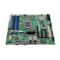
Intel S1200BT Specification (153 pages)
Product Specification
Brand:
Intel
| Category:
Server Board
| Size: 3.93 MB
Table of Contents
Revision History
2
Table of Contents
4
This Page Is Intentionally Left Blank
12
1 Introduction
13
Chapter Outline
13
Server Board Use Disclaimer
13
2 Overview
14
Intel ® Server Board S1200BT Feature Set
14
Server Board Layout
16
Figure 1. Intel Server Board S1200BTL Picture
16
Figure 2. Intel Server Board S1200BTS Picture
17
Server Board Connector and Component Layout
17
Table 2. Major Board Components
18
Figure 4. Intel Server Board S1200BTS Layout
19
Table 3. Major Board Components
19
Intel ® Server Board S1200BTL Mechanical Drawings
20
Figure 5. Intel Server Board S1200BTL - Hole and Component Positions
21
Figure 6. Intel Server Board S1200BTL - Major Connector Pin Location (1 of 2)
22
Figure 7. Intel Server Board S1200BTL - Major Connector Pin Location (2 of 2)
23
Figure 8. Intel Server Board S1200BTL - Primary Side Keepout Zone
24
Figure 9. Intel Server Board S1200BTL - Secondary Side Keepout Zone
25
Figure 10. Intel Server Board S1200BT Rear I/O Layout
26
Server Board Rear I/O Layout
26
3 Functional Architecture
27
Figure 3. Intel
27
Table 1. Intel
27
Processor Sub-System
28
Intel ® Xeon ® Processor E3-1200 Series
28
Figure 11. Intel
28
Figure 12. Intel
28
Intel ® Core™ Processor I3-2100 Series
29
Intel ® Turbo Boost Technology
29
Memory Subsystem
29
Memory Supported
30
Post Error Codes
30
Memory Map and Population Rules
31
Table 4. Memory Configuration Table
32
Table 5. UDIMM Memory Configuration Rule
32
Table 6. UDIMM Maximum Configuration
32
Publishing System Memory
33
Memory RAS Support
33
Intel ® Chipset PCH
33
I/O Sub-System
34
Digital Media Interface (DMI)
34
PCI Express Interface
34
Serial ATA Support
34
Low Pin Count (LPC) Interface
35
USB 2.0 Support
35
Integrated Baseboard Management Controller
36
Integrated BMC Embedded LAN Channel
38
Figure 13. Integrated BMC Hardware
38
Optional RMM4 Advanced Management Board
39
Serial Ports
39
Floppy Disk Controller
39
Table 7. Optional RMM4 Advanced Management Board Features
39
Table 8. Serial B Header (J1B2 on S1200BTL or J8A1 on S1200BTS) Pin-Out
39
Keyboard and Mouse Support
40
Wake-Up Control
40
Optional Intel SAS RAID Module
36
Video Support
40
Intel ® Server Board S1200BTL
40
Table 9. Video Modes
40
Video for Intel ® Server Board S1200BTS
41
Network Interface Controller (NIC)
41
Gigabit Ethernet Controller 82574L
41
Gigabit Ethernet PHY 82579
41
Table 10. Dual Video Modes
41
MAC Address Definition
42
Intel I/O Acceleration Technolgy 2 (Intel I/OAT2)
42
Direct Cache Access (DCA)
42
Intel Virtualization Technology for Directed I/O (Intel VT-D)
42
TPM (Trusted Platform Module)
43
4 Platform Management
44
Figure 14. Server Management Bus (SMBUS) Block Diagram
44
4.1 Feature Support
45
IPMI 2.0 Features
45
Non-IPMI Features
45
New Manageability Features
46
Basic and Optional Advanced Management Features
47
Table 11. Basic and Advanced Management Features
47
Enabling Advanced Management Features
48
Keyboard, Video, and Mouse (KVM) Redirection
48
Media Redirection
50
Embedded Web Server
51
Embedded Platform Debug
52
Data Center Management Interface (DCMI)
53
Local Directory Authentication Protocol (LDAP)
53
Thermal Control
53
Memory Thermal Throttling
53
Fan Speed Control
54
Intel ® Intelligent Power Node Manager
54
Overview
54
Features
55
Table 12. NM Features
55
Role of Integrated BMC in NM
56
5 Server Management Capability for Intel Server Board S1200BTS
58
Supper I/O
58
Key Features of Supper I/O
58
6 BIOS User Interface
59
BIOS POST Initialization
59
BIOS Revision Identification
59
Hotkeys Supported During POST
60
POST Logo Screen/Diagnostic Screen
61
Table 13. POST Hotkeys Recognized
61
BIOS Boot Pop-Up Menu
62
BIOS Setup Utility
62
BIOS Setup Operation
62
Table 14. BIOS Setup Page Layout
63
Table 15. BIOS Setup: Keyboard Command Bar
64
BIOS Setup Utility Screens
65
Table 16. Screen Map
66
Figure 15. Main Screen
68
Figure 16. Advanced Screen
71
Figure 17. Processor Configuration Screen
74
Figure 18. Memory Configuration Screen
80
Figure 19. Mass Storage Controller Configuration Screen
83
Figure 20. Serial Port Configuration Screen
84
Figure 21. USB Configuration Screen
85
Figure 22. PCI Configuration Screen
86
Figure 23. System Acoustic and Performance Configuration
87
Figure 24. Security Screen
87
Figure 25. Server Management Screen (S1200BTL)
88
Figure 26. Server Management Screen (S1200BTS)
89
Figure 27. Console Redirection Screen
89
Figure 28. System Information Screen (S1200BTL)
90
Figure 29.System Information Screen (S1200BTS)
91
Figure 30. BMC LAN Configuration Screen (S1200BTL)
92
Figure 31. Hardware Monitor Screen, Auto Fan Control (S1200BTS)
93
Figure 32. Hardware Monitor Screen, Manual Fan Control (S1200BTS)
93
Figure 33. Realtime Teperature and Voltage Status Screen (S1200BTS)
94
Figure 34. Boot Options Screen
95
Figure 35. Hard Disk Order Screen
96
Figure 36. CDROM Order Screen
96
Figure 37. Floppy Order Screen
97
Figure 38. Network Device Order Screen
97
Figure 39. BEV Device Order Screen
98
Figure 40. Add EFI Boot Option Screen
98
Figure 41. Delete EFI Boot Option Screen
99
Figure 42. Boot Manager Screen
99
Figure 43. Error Manager Screen
100
Figure 44. System Event Log Screen (S1200BTS)
100
Figure 45. Exit Screen
101
7 Connector/Header Locations and Pin-Outs
102
Board Connector Information
102
Table 17. Board Connector Matrix on S1200BTL
102
Power Connectors
103
Table 18. Board Connector Matrix on S1200BTS
103
Table 19. Baseboard Power Connector Pin-Out (J9G1)
103
System Management Headers
104
RMM4) Lite Connetor and Dedicated
104
NIC Connector
104
Table 20. SSI Processor 8-PIN Power Connector Pin-Out (J9A1)
104
Table 21. Intel
104
Table 22. Dedicated NIC Connector for RMM4
104
LPC/IPMB Header
105
HSBP Header
105
SGPIO Header
105
Front Control Panel Connector
105
Table 23. LPC/IPMB Header Pin-Out (J1H5)
105
Table 24. HSBP Header Pin-Out (J1J2)
105
Table 25. SGPIO Header Pin-Out (J1J3 on S1200BTL and J2J2 on S1200BTS)
105
Table 26. Front Panel SSI Standard 24-Pin Connector Pin-Out (J1C1 on S1200BTL or J1C2 on S1200BTS)
105
Power Button
106
Reset Button
107
System Status Indicator LED
107
Table 27. System Status LED Indicator States
107
I/O Connectors
108
VGA Connector
108
Rear NIC and USB Connector
108
Table 28. VGA Connector Pin-Out
108
Table 29. RJ-45 10/100/1000 NIC Connector Pin-Out
108
Sata
109
SAS Connectors
109
Table 30. RJ-45 10/100/1000 NIC Connector Pin-Out (J6A1)
109
Table 31. 6Gb/S SATA Connector Pin-Out
109
Table 32. 3Gb/S SATA Connector Pin-Out
109
Serial Port Connectors
110
Table 33. SAS Connector Pin-Out (J2H1)
110
Table 34. External Serial a Port Pin-Out (J8A1)
110
Table 35. Internal 9-Pin Serial B Header Pin-Out (J1B2)
110
USB Connector
111
Table 36. Internal USB Connector Pin-Out ( J1E1, J1D1)
111
Table 37. Pin-Out of Internal USB Connector for Low-Profile Smart Module (J3F2)
111
PCI Express* Slot/Pci Slot/Riser Card Slot
112
Table 38. Pin-Out of Adaptive Riser Slot/Pci Express Slot 6
112
Table 39. Three PCI Express* X8 Connectors (J2B2, J3B1 and J4B2)
114
Table 40. One PCI X32 Connector (J1B1)
114
Fan Headers
115
Table 41. SSI 4-Pin Fan Header Pin-Out
115
8 Jumper Blocks
116
Figure 46. Jumper Blocks (J4A2, J1F1, J1F3, J1F2, and J1E2) on S1200BTL
116
Table 42. Server Board Jumpers (J1F1, J1F2, J1F3, J1E2, and J4A2) on S1200BTL
116
CMOS Clear and Password Reset Usage Procedure
117
Figure 47. Jumper Blocks (J2G1, J1G1, J1H3, and J2J1) on S1200BTS
117
Table 43. Server Board Jumpers (J2G1, J1G1, J1H3, and J2J1) on S1200BTS
117
Clearing the CMOS
118
Clearing the Password
118
Integrated BMC Force Update Procedure (Only for the Intel Server Board S1200BTL)
119
ME Force Update Jumper
119
BIOS Recovery Jumper
120
9 Intel Light Guided Diagnostics
121
System Status LED (Only for S1200BTL)
121
Post Code Diagnostic Leds
121
Table 44. Front Panel LED Behavior Summary
121
Figure 48. POST Code Diagnostic LED Location
122
10 Design and Environmental Specifications
123
Intel Server Board S1200BT Design Specifications
123
10.2 Board-Level Calculated MTBF
123
Processor Power Support
123
Table 45. Server Board Design Specifications
123
10.3 Power Supply Output Requirements
124
Table 46. Intel
124
Table 47. 350-W Load Ratings
124
Dynamic Loading
125
Grounding
125
Remote Sense
125
Standby Outputs
125
Table 48. Voltage Regulation Limits
125
Table 49. Transient Load Requirements
125
Voltage Regulation
125
Capacitive Loading
126
Closed-Loop Stability
126
Common Mode Noise
126
Ripple/Noise
126
Table 50. Capacitve Loading Conditions
126
Table 51. Ripple and Noise
126
Timing Requirements
126
Figure 49. Output Voltage Timing
127
Table 52. Output Voltage Timing
127
Figure 50. Turn On/Off Timing (Power Supply Signals)
128
Table 53. Turn On/Off Timing
128
Protection Circuits
129
Residual Voltage Immunity in Standby Mode
129
Table 54. Over-Current Protection (OCP)
129
Table 55. Over-Voltage Protection (OVP) Limits
129
Appendix A: Integration and Usage Tips
131
Appendix B: Integrated BMC Sensor Tables
132
Table 56. BMC Core Sensors
134
Appendix C: POST Code Diagnostic LED Decoder
141
Table 57. POST Progress Code LED Example
141
Table 58. POST Progress Codes
141
Appendix D: POST Code Errors
145
Table 59. POST Error Codes and Messages
145
Table 60. POST Error Beep Codes
147
Appendix E: Supported Intel Server Chassis
148
Glossary
149
Reference Documents
153
Advertisement
Intel S1200BT Service Manual (122 pages)
Server Board
Brand:
Intel
| Category:
Motherboard
| Size: 8.22 MB
Table of Contents
Safety Information
3
Wichtige Sicherheitshinweise
3
Consignes de Sécurité
3
Instrucciones de Seguridad Importantes
3
Warnings
5
Preface
7
About this Manual
7
Product Accessories
7
Additional Information and Software
8
Table of Contents
11
Chapter 1: Server Board Features
17
Figure 1. Intel Server Board S1200BTL
17
Figure 2. Intel Server Board S1200BTS Picture
18
Table 2. Server Board Features
19
Figure 8. Intel ® SAS Entry RAID Module
21
Connector and Header Locations
22
Figure 3. Connector and Component Location
23
Figure 4. Intel ® Server Board S1200BTS Layout
25
Configuration Jumpers
26
Figure 5. Jumper Blocks (J2G1, J1G1, J1H3, and J2J1) on S1200BTS
26
Back Panel Connectors
28
Figure 6. Configuration Jumpers Location
28
Figure 7. Back Panel Connectors
28
Hardware Requirements
29
Processor
29
Table 3. NIC LED Descriptions
29
Memory
30
Table 4. Memory Configuration Table
30
Power Supply
31
RAID Support
29
Optional Hardware
31
Intel SAS RAID Module
31
Chapter 2: Server Utilities
35
Using the BIOS Setup Utility
35
Starting Setup
35
Setup Navigation Keyboard Commands
35
Table 5. BIOS Setup: Keyboard Command Bar
35
BIOS Setup Utility Screens
37
Figure 9. Main Screen
40
Figure 10. Advanced Screen
43
Figure 11. Processor Configuration Screen
45
Figure 12. Memory Configuration Screen
52
Figure 13. Mass Storage Controller Configuration Screen
55
Figure 14. Serial Port Configuration Screen
58
Figure 15. USB Configuration Screen
58
Figure 16. PCI Configuration Screen
59
Figure 17. System Acoustic and Performance Configuration
60
Figure 18. Security Screen
62
Figure 19. Server Management Screen (S1200BTL)
65
Figure 20. Server Management Screen (S1200BTS)
66
Figure 21. Console Redirection Screen
66
Figure 22. System Information Screen (S1200BTL)
67
Figure 23. System Information Screen (S1200BTS)
68
Figure 24. BMC LAN Configuration Screen (S1200BTL)
69
Figure 25. Hardware Monitor Screen, Auto Fan Control (S1200BTS)
70
Figure 26. Hardware Monitor Screen, Manual Fan Control (S1200BTS)
70
Figure 27. Realtime Teperature and Voltage Status Screen (S1200BTS)
71
Figure 28. Boot Options Screen
72
Figure 29. Hard Disk Order Screen
73
Figure 30. CDROM Order Screen
73
Figure 31. Floppy Order Screen
74
Figure 32. Network Device Order Screen
74
Figure 33. BEV Device Order Screen
75
Figure 34. Add EFI Boot Option Screen
75
Figure 35. Delete EFI Boot Option Screen
76
Figure 36. Boot Manager Screen
76
Figure 37. Error Manager Screen
77
Figure 38. System Event Log Screen (S1200BTS)
77
Upgrading the BIOS
78
Preparing for the Upgrade
78
Figure 39. Exit Screen
78
Upgrading the BIOS
79
Recovering the BIOS
79
Recovering the BIOS
81
Figure 40. BIOS Recovery Jumper
81
Clearing the Password
82
Figure 41. Password Recovery Jumper
82
Figure 42. CMOS Recovery Jumper
83
Figure 43. BMC Force Update Jumper
83
Chapter 3: Hardware Installations and Upgrades
85
Before You Begin
85
Tools and Supplies Needed
85
Installing and Removing Memory
85
Installing Dimms
85
Removing Dimms
86
Figure 44. Installing Memory
86
Installing the Processor
87
Figure 45. Lifting the Load Lever
88
Figure 46. Open the Load Plate
88
Figure 47. Remove the Socket Protective Cover
89
Figure 48. Remove the Processor Protective Cover
89
Figure 49. Installing the Processor
89
Installing the Heatsink(S)
90
Figure 50. Close the Load Plate and Socket Lever
90
Removing a Processor
91
Figure 51. 2U Reference Heatsink Assembly
91
Installing a PCI Card
92
Figure 52. Removing the PCI Riser Assembly from the Server System
92
Figure 53. Installing a PCI Card in a Riser Card
93
Replacing the Backup Battery
94
Figure 54. Replacing the Backup Battery
95
Appendix A: LED Decoder
97
Figure 55. Diagnostic LED Placement Diagram
97
Table 6. POST Progress Code LED Example
98
Table 7. Diagnostic LED POST Code Decoder
98
Appendix B: Intel ® Server Issue Report Form
103
Appendix C: Getting Help
109
Warranty Information
109
Appendix D: Troubleshooting
111
System Boot Quiet Time
111
Resetting the System
111
Table 8. Resetting the System
111
Problems Following Initial System Installation
112
First Steps Checklist
112
Hardware Diagnostic Testing
113
Verifying Proper Operation of Key System Lights
113
Confirming Loading of the Operating System
113
Specific Problems and Corrective Actions
114
Power Light Does Not Light
114
No Characters Display on Screen
115
Characters Are Distorted or Incorrect
115
System Cooling Fans Do Not Rotate Properly
116
Drive Activity Light Does Not Light
116
CD-ROM Drive or DVD-ROM Drive Activity Light Does Not Light
116
Cannot Connect to a Server
117
Problems with Network
117
System Boots When Installing PCI Card
118
Problems with Newly Installed Application Software
118
Problems with Application Software that Ran Correctly Earlier
119
Devices Are Not Recognized under Device Manager (Microsoft Windows* Operating System)
119
Hard Drive(S) Are Not Recognized
119
Bootable CD-ROM Disk Is Not Detected
120
LED Information
120
BIOS POST Beep Codes
120
Table 9. LED Information
120
Table 10. POST Error Beep Codes
121
Advertisement
Related Products
Intel S1200BTS
Intel S1200V3RP
Intel S1200RP
Intel S1200SPL
Intel S1200SPS
Intel S1200SPO
Intel SR2400
Intel S815EBM1 - Server Board Motherboard
Intel S845WD1H
Intel S845WD1-E - Server Board Motherboard
Intel Categories
Motherboard
Computer Hardware
Server
Server Board
Desktop
More Intel Manuals
Login
Sign In
OR
Sign in with Facebook
Sign in with Google
Upload manual
Upload from disk
Upload from URL