Sign In
Upload
Download
Table of Contents
Contents
Add to my manuals
Delete from my manuals
Share
URL of this page:
HTML Link:
Bookmark this page
Add
Manual will be automatically added to "My Manuals"
Print this page
×
Bookmark added
×
Added to my manuals
Manuals
Brands
Intel Manuals
Server Board
S1200SPL
Technical spesification
Intel S1200SPL Technical Spesification
S1200sp family
Hide thumbs
1
2
3
4
5
Table Of Contents
6
7
8
9
10
11
12
13
14
15
16
17
18
19
20
21
22
23
24
25
26
27
28
29
30
31
32
33
34
35
36
37
38
39
40
41
42
43
44
45
46
47
48
49
50
51
52
53
54
55
56
57
58
59
60
61
62
63
64
65
66
67
68
69
70
71
72
73
74
75
76
77
78
79
80
81
82
83
84
85
86
87
88
89
90
91
92
93
94
95
96
97
98
99
100
101
102
103
104
105
106
107
108
109
110
111
112
113
114
115
116
117
118
119
120
121
122
123
124
125
126
127
128
129
130
131
132
133
134
135
136
137
138
139
140
141
142
143
144
145
146
147
page
of
147
Go
/
147
Contents
Table of Contents
Bookmarks
Table of Contents
Table of Contents
1 Introduction
Chapter Outline
Server Board Use Disclaimer
2 Overview
Intel ® Server Board S1200SP Family Feature Set
Table 1. Intel
Table 2. Limiting Conditions of Pcie* Card Form Factor
Table 4. Intel
Table 11. Intel
Server Board Layout
Figure 1. Intel Server Board S1200SP Layout (S1200SPL)
Figure 2. Intel Server Board S1200SPL Layout
Server Board Connector and Component Layout
Figure 3. Intel Server Board S1200SPS Layout
Figure 4. Intel Server Board S1200SPO Layout
Figure 5. Intel Server Board S1200SP - Mounting Hole Locations
Server Board Mechanical Drawings
Figure 6. Intel® Server Board S1200SP - Mounting Hole Locations (Continued)
Figure 7. Intel Server Board S1200SP - Major Connector Pin-1 Locations
Figure 8. Intel® Server Board S1200SP - Major Connector Pin-1 Locations (Continued)
Figure 9. Intel® Server Board S1200SP - Primary Side Keepout Zone
Figure 10. Intel® Server Board S1200SP - Second Side Keepout Zone
Figure 11. Intel Server Board S1200SPL Rear I/O Layout
Figure 12. Intel Server Board S1200SPS Rear I/O Layout
Figure 13. Intel Server Board S1200SPO Rear I/O Layout
Server Board Rear I/O Layout
3 Functional Architecture
Processor Subsystem
Intel
Th Generation Intel Core I3 Processors
Processor Function Overview
Integrated Memory Controller (IMC) and Memory Subsystem
Supported Memory
Table 3. UDIMM Support Guidelines
Table 5. Intel Server Board S1200SP DIMM Maximum Configuration
Memory RAS Features
Post Error Codes
Processor Integrated I/O Module (IIO)
Intel Integrated RAID Option
Optional I/O Module Support
Intel
I/O At2)
Intel C230 Series Chipset PCH Functional Overview
Figure 13. Intel
Figure 14. Intel
Table 6. Intel® C230 Series Chipset Features
Digital Media Interface (DMI)
PCI Express* Interface
Serial ATA (SATA) Controller
Figure 15. Intel® Server Board S1200SP Series USB Mapping Diagram
Low Pin Count (LPC) Interface
Serial Peripheral Interface (SPI)
Universal Serial Bus (USB) Controller
Gigabit Ethernet Controller
Kvm/Serial over LAN (SOL) Function
Serial Ports
Table 7. External RJ45 NIC Port LED Definition
Intel Virtualization Technology for Direct I/O (Intel VT-D)
System Management Bus (Smbus* 2.0)
Integrated Baseboard Management Controller (BMC) Overview
Super I/O Controller
Figure 16. Integrated BMC Functional Block Diagram
Remote Keyboard, Video, Mouse, and Storage (KVMS)
Graphics Controller and Video Support
Table 8. Onboard Video Resolution and Refresh Rate (Hz)
4 System Security
BIOS Password Protection
Trusted Platform Module (TPM) Support
TPM Security BIOS
Physical Presence
TPM Security Setup Options
Figure 17. Setup Utility - TPM Configuration Screen
Table 9. TPM Setup Utility - Security Configuration Screen Fields
Intel
Trusted Execution Technology
5 Intel Technology Support
Intel Trusted Execution Technology
Intel Virtualization Technology - Intel VT-X/Vt-D/Vt-C
Intel Intelligent Power Node Manager
Table 10. Intel Intelligent Power Node Manager
Hardware Requirements
6 Platform Management Functional Overview
Baseboard Management Controller (BMC) Firmware Feature Support
IPMI 2.0 Features
Non-IPMI Features
Basic and Advanced Features
Table 12. Basic and Advanced Features
Advanced Configuration and Power Interface (ACPI)
Table 13. ACPI Power States
Power Control Sources
BMC Watchdog
Table 14. Power Control Initiators
Fault Resilient Booting (FRB)
Sensor Monitoring
Field Replaceable Unit (FRU) Inventory Device
System Event Log (SEL)
System Fan Management
Thermal and Acoustic Management
Thermal Sensor Input to Fan Speed Control
Auto Profiles
Figure 18. Fan Speed Control Process
Memory Thermal Throttling
Messaging Interfaces
Table 15. Messaging Interfaces
IPMB Communication Interface
User Model
LAN Interface
Address Resolution Protocol (ARP)
Internet Control Message Protocol (ICMP)
Virtual Local Area Network (VLAN)
Platform Event Filter (PEF)
Secure Shell (SSH)
Serial-Over-LAN (SOL 2.0)
Alert Policy Table
LAN Alerting
Table 16. Factory Configured PEF Table Entries
Embedded Web Server
SM-CLP (SM-CLP Lite)
Virtual Front Panel
Embedded Platform Debug
Table 17. Diagnostic Data
Data Center Management Interface (DCMI)
Lightweight Directory Access Protocol (LDAP)
Table 18. Additional Diagnostics on Error
7 Advanced Management Feature Support (RMM4)
Dedicated Management Port
Keyboard, Video, and Mouse (KVM) Redirection
Table 19. Intel® Remote Management Module 4 (RMM4) Options
Remote Console
Availability
Force-Enter BIOS Setup
Performance
Security
Usage
Media Redirection
Availability
Network Port Usage
8 On-Board Connector/Header Overview
Board Connector Information
Table 20. Board Connector Matrix
Power Connectors
Table 21. Main Power Connector Pin-Out (J9H1)
Table 22. CPU Power Connector Pin-Out (J9B1)
System Management Headers
Intel Remote Management Module 4 Lite Connector
Figure 19. Intel
Table 23. PMBUS SSI Connector Pin-Out (J9F1)
Table 24. Battery Holder (BT2F1)
Table 25. Stacked Connector of USB 3.0+ Dedicated RJ45 Management Port Pin-Out (JA5A1)
TPM Connector
Intel
ESRT2 RAID Upgrade Key Connector
HSBP SMBUS Header
Table 26. Intel RMM4 - Lite Connector Pin-Out (J3B1)
Table 27. TPM Connector Pin-Out (J8K1)
Table 28. Intel ESRT2 RAID Upgrade Key Connector Pin-Out (J9K1)
Table 29. HSBP SMBUS Header Pin-Out (J3K3)
Chassis Intrusion Header
SATA SGPIO Header
IPMB Connector
Front Panel Connector
Table 30. Chassis Intrusion Header Pin-Out (J9B2)
Table 31. SATA SGPIO Header Pin-Out (J2K5, J2K6)
Table 32. IPMB Connector Pin-Out (J1G2)
Power/Sleep Button and LED Support
System ID Button and LED Support
System Reset Button Support
Table 33. Front Panel 24-Pin Connector Pin-Out (J9E1)
Table 34. Power/Sleep LED Functional States
Hard Drive Activity LED Support
NIC Activity LED Support
NMI Button Support
System Status LED Support
I/O Connectors
VGA Connector
Table 35. NMI Signal Generation and Event Logging
Display Port Connector
SATA Connectors
Table 36. VGA Connector Pin-Out (J8A1)
Table 37. Display Port Connector Pin-Out (J4A1)
SATA Connector (J2G1)
Figure 20. Installing M.2 Device
Table 38. SATA/SATADOM Capable Connector Pin-Out (J1K4, J1K1, J1K5, J1K2, J2K4, J2K3, J2K1, J2K2)
Serial Port Connector
Table 39. M.2 SATA Connector Pinout
Table 40. Internal 9-Pin Serial Header Pin-Out (J9A1)
USB Connector
Table 41. USB 2.0 FP Header (J1J2)
Table 42. USB3.0 FP Header (J1J1)
Table 43. USB 2.0 Connector (Rear IO) (J6A1)
Table 44. Internal Type a USB Port Pin-Out (J1K3)
I/O Module Connector
Table 45. I/O Module Connector Pin-Out (J1C1)
SAS/ROC Module Connector
Figure 21. Installing Intel Integrated RAID Module
Table 45. I/O Module Connector Pin-Out (J4J1)
NIC Connector
Fan Headers
Table 46. NIC Connector Pin-Out (JA7A1, J6A2)
Figure 22. Fan Headers on the Server Borad
Table 47. SSI 4-Pin Fan Header Pin-Out (J3K2, J8B1, J7K1, J8K2, J8K3)
9 Jumper Blocks
Figure 23. Jumper Blocks (J4B1, J1F1, J1F4 J7B1, J4C1)
BIOS Default Jumper (J4C1)
BIOS Recovery Jumper (J7B1)
Table 48. Server Board Jumpers (J4B1, J1F1, J1F4, J7B1, J4C1)
Password Clear Jumper (J1F4)
BMC Force Update Jumper (J4B1)
Management Engine (ME) Firmware Force Update Jumper (J1F1)
10 Intel Light Guided Diagnostics
System ID LED
System Status LED
Figure 24. On-Board LED Placement
Table 49. System Status LED State Definitions
BMC Boot/Reset Status LED Indicators
Post Code Diagnostic Leds
Volt Stand-By Present LED
Table 50. BMC Boot/Reset Status LED Indicators
11 Environmental Limits Specification
Processor Thermal Design Power (TDP) Support
Table 51. Server Board Design Specifications
Mtbf
Table 52. MTBF Estimate
12 Server Board Power Distribution
DC Output Specification
Output Power/Currents
Figure 25. Power Distribution Block Diagram
Standby Output
Voltage Regulation
Dynamic Loading
Capacitive Loading
Grounding
Closed Loop Stability
Residual Voltage Immunity in Standby Mode
Common Mode Noise
Soft Starting
Zero Load Stability Requirements
Hot Swap Requirements
Forced Load Sharing
Ripple / Noise
Figure 26. Differential Noise Test Setup
Figure 27. Turn On/Off Timing (Power Supply Signals)
Appendix A. Integration and Usage Tips
Appendix B. Integrated BMC Sensor Tables
Appendix C. POST Code Diagnostic LED Decoder
Figure 28. POST Code Diagnostic Leds
Appendix D. POST Code Errors
Appendix E. Supported Intel
Server Chassis
Figure 29. Processor Heatsink Installation
Advertisement
Quick Links
1
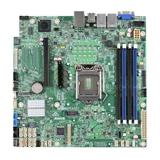
Figure 1. Intel Server Board S1200Sp Layout (S1200Spl)
Download this manual
®
Intel
Server Board S1200SP
Product Family
Technical Product Specification
A document providing an overview of product features, functions, architecture, and
support specifications
Revision 1.7
February, 2018
Intel Server Products and Solutions
Table of
Contents
Previous
Page
Next
Page
1
2
3
4
5
Advertisement
Table of Contents
Need help?
Do you have a question about the S1200SPL and is the answer not in the manual?
Ask a question
Questions and answers
Related Manuals for Intel S1200SPL
Server Board Intel S1200BTS Specification
Product specification (153 pages)
Server Board Intel S1200BTLRM Quick Start Manual
(1 page)
Server Board Intel S1200V3RP Technical Product Specification
(270 pages)
Server Board Intel S1200V3RP Quick Start User Manual
(2 pages)
Server Board Intel S1400SP Technical Manual
(162 pages)
Server Board Intel S1200RP Getting Started
Uefi development kit (17 pages)
Server Board Intel S1200SPS Technical Spesification
S1200sp family (147 pages)
Server Board Intel S1200SPO Technical Spesification
S1200sp family (147 pages)
Server Board Intel S5500HCV Spares Parts List & Configuration Manual
Server board, workstation board and server chassis (24 pages)
Server Board Intel S3420GP Manual
Intel - server motherboard (88 pages)
Server Board Intel S5000PAL Installation Manual
Vmware infrastructure 3 vmware esxi 3.5 installable server board (42 pages)
Server Board Intel S3420GPRX User Manual
User guide (78 pages)
Server Board Intel SE7520AF2 Technical Product Specification
(256 pages)
Server Board Intel SE7501CW2 - E7501 DUAL PGA604 XEON 533MHZ Product Manual
Product guide (93 pages)
Server Board Intel Server Board S5500HV Technical Product Specification
(92 pages)
Server Board Intel S2600CW Technical Product Specification
(210 pages)
This manual is also suitable for:
S1200spo
S1200sps
Table of Contents
Save PDF
Print
Rename the bookmark
Delete bookmark?
Delete from my manuals?
Login
Sign In
OR
Sign in with Facebook
Sign in with Google
Upload manual
Upload from disk
Upload from URL


Need help?
Do you have a question about the S1200SPL and is the answer not in the manual?
Questions and answers