Sign In
Upload
Manuals
Brands
Intel Manuals
Server Board
S1200BTS
Intel S1200BTS Manuals
Manuals and User Guides for Intel S1200BTS. We have
2
Intel S1200BTS manuals available for free PDF download: Software User's Manual, Specification
Intel S1200BTS Software User's Manual (204 pages)
Software User's Guide
Brand:
Intel
| Category:
Server
| Size: 9.46 MB
Table of Contents
Table of Contents
3
Chapter 1: Overview
15
Supported Hardware
15
Software
17
RAID Terminology
18
Fault Tolerance
18
Hot Spare
19
Enclosure Management
20
Performance
20
Disk Striping
21
Disk Spanning
21
Cpu Usage
21
Chapter 2: RAID Levels
23
Summary of RAID Levels
23
Selecting a RAID Level
24
RAID 0 - Data Striping
24
Figure 1. RAID 0 - Data Striping
24
Table 1. RAID 0 Overview
24
RAID 1 - Disk Mirroring/Disk Duplexing
25
RAID 5 - Data Striping with Striped Parity
25
Figure 2. RAID 1 - Disk Mirroring/Disk Duplexing
25
Table 2. RAID 1 Overview
25
RAID 6 - Distributed Parity and Disk Striping
26
Figure 3. RAID 5 - Data Striping with Striped Parity
26
Table 3. RAID 5 Overview
26
Table 4. RAID 6 Overview
26
Raid Ime
27
Figure 4. Example of Distributed Parity Across Two Blocks in a Stripe (RAID 6)
27
RAID 10 - Combination of RAID 1 and RAID 0
28
Figure 5. Integrated Mirroring Enhanced with Three Disks
28
Table 5. RAID 1E Overview
28
RAID 50 - Combination of RAID 5 and RAID 0
29
Figure 6. RAID 10 - Combination of RAID 1 and RAID 0
29
Table 6. RAID 10 Overview
29
RAID 60 - Combination of RAID 0 and RAID 6
30
Figure 7. RAID 50 - Combination of RAID 5 and RAID 0
30
Table 7. RAID 50 Overview
30
Table 8. RAID 60 Overview
31
Figure 8. RAID 60 Level Virtual Drive
32
RAID Configuration Strategies
33
Maximizing Fault Tolerance
33
Table 9. RAID Levels and Fault Tolerance
33
Maximizing Performance
34
Table 10. RAID Levels and Performance
34
Maximizing Storage Capacity
35
Table 11. RAID Levels and Capacity
36
RAID Availability
37
RAID Availability Concept
37
Spare Drives
37
Rebuilding
37
Drive in Foreign State
37
Copyback
38
Configuration Planning
38
Dimmer Switch Feature
39
Number of Physical Disks
39
Megaraid Fast Path
39
4K Sector Drive Support
39
Larger than 2TB Drive Support
40
Power Save Settings
40
Shield State
40
Array Purpose
41
Table 12. Factors to Consider for Array Configuration
41
Chapter 3: RAID Utilities
43
Intel Embedded Server RAID Technology 2 BIOS Configuration Utility
43
LSI MPT* SAS BIOS Configuration Utility
43
Intel RAID BIOS Console 2 Configuration Utility for Intelligent RAID
44
Intel RAID Web Console 2 Configuration and Monitoring Utility
45
Drive Hierarchy Within the RAID Firmware
46
Intel Intelligent RAID Controller Features
46
Enterprise Features
46
Fault Tolerant Features
47
Cache Options and Settings
48
Background Tasks
48
Error Handling
49
Audible Alarm
49
Chapter 4: Intel ® RAID Drivers
51
RAID Driver Installation for Microsoft Windows
51
Installation in a New Microsoft Windows* Operating System
51
Installation in an Existing Microsoft Windows* Operating System
52
RAID Driver Installation for Red Hat* Enterprise Linux
52
RAID Driver Installation for Suse* Linux
53
RAID Driver Installation for Novell Netware
53
Installation in a New Novell Netware* System
53
Installation in an Existing Novell Netware* System
54
RAID Driver Installation for Solaris* 10
54
Installation in a New Solaris* System
54
Installation in an Existing Solaris* System
54
Chapter 5: Intel ® Embedded Server RAID BIOS Configuration Utility
55
Creating, Adding or Modifying a Virtual Drive Configuration
56
Figure 9. Intel ® Embedded Server RAID BIOS Configuration Utility Screen
56
Raid Level
57
Stripe Size
57
Setting the Write Cache and Read Ahead Policies
58
Working with a Global Hot-Spare Drive
58
Adding a Hot-Spare Drive
59
Removing a Hot-Spare Drive
59
Rebuilding a Drive
59
Auto Rebuild and Auto Resume
59
Checking Data Consistency
60
Viewing and Changing Device Properties
60
Forcing a Drive Online or Offline
61
Configuring a Bootable Virtual Drive
61
Deleting (Clearing) a Storage Configuration
61
Chapter 6: Intel IT/IR RAID Configuration
63
IM and IME Configuration Overview
63
Features
63
Creating IM and IME Volumes
64
Creating an IM Volume
65
Figure 10. Adapter Properties Screen
65
Creating an IME Volume
66
Figure 11. Create New Array Screen
66
Creating a Second IM or IME Volume
67
Managing Hot Spares
67
Figure 12. Manage Array Screen
68
Other Configuration Tasks
69
Viewing Volume Properties
69
Synchronizing an Array
69
Activating an Array
69
Deleting an Array
70
Locating a Drive or Multiple Drives in a Volume
70
Selecting a Boot Disk
71
IS Configuration Overview
71
Creating IS Volumes
72
Figure 13. Adapter Properties Screen
72
Creating a Second IS Volume
73
Figure 14. Create New Array Screen
73
Other Configuration Tasks
74
Viewing IS Volume Properties
74
Activating an Array
74
Deleting an Array
74
Locating a Disk Drive, or Multiple Disk Drives in a Volume
75
Selecting a Boot Disk
75
Chapter 7: Intel ® RAID BIOS Console 2 Utility
77
Quick Configuration Steps
77
Detailed Configuration Steps Using the Intel
78
RAID BIOS Console 2
78
Start the Intel ® RAID BIOS Console 2 Utility
78
Screen and Option Descriptions
78
Table 13. Intel ® RAID BIOS Console 2 Toolbar Icon Descriptions
78
Figure 15. Intel RAID BIOS Console 2 Menu
79
Main Screen
79
Figure 16. Intel ® RAID BIOS Console 2 - Controller Selection
80
Figure 17. Controller Properties
80
Figure 18. Additional Controller Properties
81
Setting up a RAID Array Using the Configuration Wizard
84
Figure 19. Intel RAID BIOS Console 2 - Configuration Types
84
Figure 20. Selecting Configuration
85
Figure 21. Intel RAID BIOS Console 2 - Configuration Methods
86
RAID BIOS Console 2 (Detailed)
87
Figure 22. Intel ® RAID BIOS Console 2 - Add Physical Drives to Array
87
Figure 23. Intel RAID BIOS Console 2 - Set Array Properties
88
Figure 24. Intel RAID BIOS Console 2 - Confirm Configuration
89
Figure 25. Intel RAID BIOS Console 2 - Initialization Speed Setting
90
Creating RAID 10, RAID 50, and RAID 60 Using Intel
91
RAID BIOS Console 2
91
Figure 26. Intel ® RAID BIOS Console 2 - Multiple Disk Groups for RAID 10, 50, or 60
91
Figure 27. Intel RAID BIOS Console 2 - Spanning Multiple Arrays
92
Figure 28. Intel RAID BIOS Console 2 - Viewing Completed Settings
93
Figure 29. Intel RAID BIOS Console 2 - Initialization Settings
94
Figure 30. Intel RAID BIOS Console 2 - RAID 10 Final Screen
94
Figure 31. Intel RAID BIOS Console 2 - RAID 10 Properties Screen
95
Figure 32. Intel RAID BIOS Console 2 - RAID 50 Properties Screen
95
Setting Drive Parameters
96
Creating a Hot Spare
97
Figure 33. Intel RAID BIOS Console 2 - Choosing a Hot Spare Drive
97
Figure 34. Intel RAID BIOS Console 2 - Setting a Hot Spare Drive
98
Figure 35. Intel RAID BIOS Console 2 - Viewing Hot Spare
98
Figure 36. Intel RAID BIOS Console 2 - Main Screen Showing Hot Spare Drive
99
Viewing Event Details
100
Figure 37. Intel RAID BIOS Console 2 - Event Information Screen
100
Figure 38. Intel RAID BIOS Console 2 - Selecting Events to View
101
Figure 39. Intel RAID BIOS Console 2 - Viewing an Event
101
Chapter 8: Intel ® RAID Web Console 2
103
Configuration Functions
103
Monitoring Functions
103
Maintenance Functions
104
Hardware and Software Requirements
104
Installing the Intel RAID Web Console 2 on a Microsoft Windows* Operating System
104
Figure 40. Intel ® RAID Web Console 2 - Customer Information Screen
105
Figure 41. Setup Type Screen
105
Installing the Intel ® RAID Web Console 2 on Linux or Suse* Linux Enterprise Server
106
Intel RAID Web Console 2 Support and Installation on Vmware
106
Installing Intel ® RAID Web Console 2 for Vmware Classic
106
Uninstalling Intel ® RAID Web Console 2 for Vmware
106
Installing Intel RAID Web Console 2 Support on the Vmware ESX
107
Starting the Intel ® RAID Web Console 2
112
Intel RAID Web Console 2 Screens
112
Figure 42. Intel ® RAID Web Console 2 - Select Server Screen
112
Figure 43. Intel RAID Web Console 2 - Login Screen
113
Figure 44. Intel RAID Web Console 2 Dashboard
114
Physical/Virtual View Panel
115
Figure 45. Intel ® RAID Web Console 2 - Main Screen
115
Properties/Operations/Graphical View Panel
116
Figure 46. Intel RAID Web Console 2 - Operations Tab
116
Event Log Panel
117
Figure 47. Intel RAID Web Console 2 - Graphical Tab (Optional Feature)
117
Menu Bar/Manage Menu
118
Menu Bar/Go to Menu
118
File Menu/Log Menu
118
File Menu/Tool Menu
118
File Menu/Help Menu
118
Drive Configuration Tasks
118
Create Virtual Drive
119
Creating a Virtual Drive Using Simple Configuration
119
Figure 48. Virtual Drive Creation Menu
120
Figure 49. Virtual Drive Creation Mode
120
Figure 50. Create Virtual Drive Screen
121
Figure 51. Create Virtual Drive - Summary Window
122
Figure 52. Option to Create Additional Virtual Drives
122
Creating a Virtual Drive Using Advanced Configuration
123
Figure 53. Option to Close the Configuration Wizard
123
Figure 54. Virtual Drive Creation Menu
124
Figure 55. Virtual Drive Creation Mode
124
Figure 56. Create Drive Group Settings Screen
125
Figure 57. Span 0 of Drive Group 0
126
Figure 58. Span 0 and Span 1 of Drive Group 0
126
Figure 59. Virtual Drive Settings Window
127
Figure 60. New Virtual Drive 0
128
Figure 61. Create Virtual Drive Summary Window
128
Figure 62. Option to Create Additional Virtual Drives
129
Figure 63. Option to Close the Configuration Wizard
129
Creating a Spanned Disk Group
130
Creating Hot Spares
131
Figure 64. Assign Global Hotspare
131
Figure 65. Assign Dedicated Hotspare
132
Figure 66. Select Hotspare Drive
132
Setting Adjustable Task Rates
133
Figure 67. Set Adjustable Task Rates
133
Adding a Drive to a Virtual Disk
134
Figure 68. Starting Modify Drive Group
135
Figure 69. Select RAID Level to Migrate
135
Figure 70. Selecting Drives to Add
136
Figure 71. Changing RAID Level
136
Removing a Drive or Changing the RAID Level of a Virtual Disk
137
Figure 72. Selecting Drives to Remove
137
Changing Virtual Disk Properties
138
Figure 73. Changing RAID Level
138
Deleting a Virtual Disk
139
Figure 74. Set Virtual Disk Properties
139
Managing Configurations
140
Saving a Configuration to Disk
140
Figure 75. Save Configuration to File
140
Figure 76. Save Configuration Dialog Box
141
Clearing a Configuration from a Controller
142
Figure 77. Clear Configuration
142
Adding a Configuration from a File
143
Figure 78. Add Saved Configuration
143
Monitoring System Events and Devices
144
Monitoring System Events
144
Figure 79. Event Information Window
144
Monitoring Controllers
145
Figure 80. Controller Information
145
Monitoring Disk Drives and Other Physical Devices
146
Figure 81. Physical Drive Information
146
Figure 82. Locating a Physical Drive
147
Figure 83. Patrol Read Configuration
148
Running a Patrol Read
148
Monitoring Virtual Disks
149
Monitoring Enclosures
149
Figure 84. Virtual Drive Properties
149
Monitoring Battery Backup Units
150
Figure 85. Enclosure Information
150
Battery Learn Cycle
151
Figure 86. Battery Backup Unit Information
151
Figure 87. Battery Backup Unit Operations
152
Monitoring Rebuilds and Other Processes
153
Figure 88. Group Show Progress Window
153
Maintaining and Managing Storage Configurations
154
Initializing a Virtual Disk
154
Figure 89. Selecting Initialize
154
Running a Consistency Check
155
Figure 90. Group Consistency Check Window
155
Scanning for New Drives
156
Rebuilding a Drive
156
Figure 91. Scan for Foreign Configuration
156
Removing a Drive
157
Figure 92. Preparing Drive for Removal
157
Flashing the Firmware
158
Enabling RAID Premium Features
158
Enabling Full Disk Encryption Feature
158
Figure 93. Check Controller Security Status
159
Figure 94. Check Drive Security Status
160
Figure 95. Enable Drive Security
160
Figure 96. Start Security Wizard
161
Figure 97. Enter Security Key Identifier
161
Figure 98. Enter Security Key
162
Figure 99. Enter Pass Phrase
163
Figure 100. Confirm Enable Drive Security
163
Figure 101. Check Drive Security Enabled Status
164
Figure 102. Select Full Disk Encryption
164
Figure 103. Create RAID Virtual Drive with FDE Enabled
165
Figure 104. Instant Secure Erase
166
Figure 105. Confirm Secure Erase
166
Enabling Snapshot Feature
167
Figure 106. Enable Megaraid Recovery
168
Figure 107. Enter the Capacity for Snapshot Respository
168
Figure 108. Confirm Enable Snapshot
169
Figure 109. Snapshot Base Is Shown
170
Figure 110. Enter Snapshot Name
170
Figure 111. Create Snapshot
171
Figure 112. Create View
171
Figure 113. Set Megaraid Recovery Properties
172
Figure 114. Disable Megaraid Recovery
173
Figure 115. Confirm Disable Snapshots
173
Figure 116. Adapter Selection
174
Figure 117. Selecting Snapshot Base
174
Figure 118. Selecting Advanced Operations
175
Figure 119. Selecting Rollback
175
Figure 120. Selecting a Snapshot
176
Figure 121. Confirm Page
176
Enabling Super Sized Cache
177
Figure 122. Rollback Operation Is Done
177
Figure 123. Create SSC from Dashboard
178
Figure 124. Create SSC Drive Group
178
Figure 125. Create SSCD Name
179
Figure 126. SSC Summary
179
Figure 127. SSCD Status Shown
180
Figure 128. Delete SSCD
180
Appendix A: Creating a Virtual Drive Using Advanced Configuration
181
Figure 129. Virtual Drive Creation Menu
181
Figure 130. Virtual Drive Creation Mode
182
Figure 131. Create Drive Group Settings Screen
183
Figure 132. Span 0 of Drive Group 0
184
Figure 133. Span 0 and Span 1 of Drive Group 0
185
Figure 134. Virtual Drive Settings Window
186
Figure 135. New Virtual Drive 0
187
Figure 136. Create Virtual Drive Summary Window
187
Table 14. MFI Messages
190
Advertisement
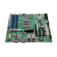
Intel S1200BTS Specification (153 pages)
Product Specification
Brand:
Intel
| Category:
Server Board
| Size: 3.93 MB
Table of Contents
Revision History
2
Table of Contents
4
This Page Is Intentionally Left Blank
12
1 Introduction
13
Chapter Outline
13
Server Board Use Disclaimer
13
2 Overview
14
Intel ® Server Board S1200BT Feature Set
14
Server Board Layout
16
Figure 1. Intel Server Board S1200BTL Picture
16
Figure 2. Intel Server Board S1200BTS Picture
17
Server Board Connector and Component Layout
17
Table 2. Major Board Components
18
Figure 4. Intel Server Board S1200BTS Layout
19
Table 3. Major Board Components
19
Intel ® Server Board S1200BTL Mechanical Drawings
20
Figure 5. Intel Server Board S1200BTL - Hole and Component Positions
21
Figure 6. Intel Server Board S1200BTL - Major Connector Pin Location (1 of 2)
22
Figure 7. Intel Server Board S1200BTL - Major Connector Pin Location (2 of 2)
23
Figure 8. Intel Server Board S1200BTL - Primary Side Keepout Zone
24
Figure 9. Intel Server Board S1200BTL - Secondary Side Keepout Zone
25
Figure 10. Intel Server Board S1200BT Rear I/O Layout
26
Server Board Rear I/O Layout
26
3 Functional Architecture
27
Figure 3. Intel
27
Table 1. Intel
27
Processor Sub-System
28
Intel ® Xeon ® Processor E3-1200 Series
28
Figure 11. Intel
28
Figure 12. Intel
28
Intel ® Core™ Processor I3-2100 Series
29
Intel ® Turbo Boost Technology
29
Memory Subsystem
29
Memory Supported
30
Post Error Codes
30
Memory Map and Population Rules
31
Table 4. Memory Configuration Table
32
Table 5. UDIMM Memory Configuration Rule
32
Table 6. UDIMM Maximum Configuration
32
Publishing System Memory
33
Memory RAS Support
33
Intel ® Chipset PCH
33
I/O Sub-System
34
Digital Media Interface (DMI)
34
PCI Express Interface
34
Serial ATA Support
34
Low Pin Count (LPC) Interface
35
USB 2.0 Support
35
Integrated Baseboard Management Controller
36
Integrated BMC Embedded LAN Channel
38
Figure 13. Integrated BMC Hardware
38
Optional RMM4 Advanced Management Board
39
Serial Ports
39
Floppy Disk Controller
39
Table 7. Optional RMM4 Advanced Management Board Features
39
Table 8. Serial B Header (J1B2 on S1200BTL or J8A1 on S1200BTS) Pin-Out
39
Keyboard and Mouse Support
40
Wake-Up Control
40
Optional Intel SAS RAID Module
36
Video Support
40
Intel ® Server Board S1200BTL
40
Table 9. Video Modes
40
Video for Intel ® Server Board S1200BTS
41
Network Interface Controller (NIC)
41
Gigabit Ethernet Controller 82574L
41
Gigabit Ethernet PHY 82579
41
Table 10. Dual Video Modes
41
MAC Address Definition
42
Intel I/O Acceleration Technolgy 2 (Intel I/OAT2)
42
Direct Cache Access (DCA)
42
Intel Virtualization Technology for Directed I/O (Intel VT-D)
42
TPM (Trusted Platform Module)
43
4 Platform Management
44
Figure 14. Server Management Bus (SMBUS) Block Diagram
44
4.1 Feature Support
45
IPMI 2.0 Features
45
Non-IPMI Features
45
New Manageability Features
46
Basic and Optional Advanced Management Features
47
Table 11. Basic and Advanced Management Features
47
Enabling Advanced Management Features
48
Keyboard, Video, and Mouse (KVM) Redirection
48
Media Redirection
50
Embedded Web Server
51
Embedded Platform Debug
52
Data Center Management Interface (DCMI)
53
Local Directory Authentication Protocol (LDAP)
53
Thermal Control
53
Memory Thermal Throttling
53
Fan Speed Control
54
Intel ® Intelligent Power Node Manager
54
Overview
54
Features
55
Table 12. NM Features
55
Role of Integrated BMC in NM
56
5 Server Management Capability for Intel Server Board S1200BTS
58
Supper I/O
58
Key Features of Supper I/O
58
6 BIOS User Interface
59
BIOS POST Initialization
59
BIOS Revision Identification
59
Hotkeys Supported During POST
60
POST Logo Screen/Diagnostic Screen
61
Table 13. POST Hotkeys Recognized
61
BIOS Boot Pop-Up Menu
62
BIOS Setup Utility
62
BIOS Setup Operation
62
Table 14. BIOS Setup Page Layout
63
Table 15. BIOS Setup: Keyboard Command Bar
64
BIOS Setup Utility Screens
65
Table 16. Screen Map
66
Figure 15. Main Screen
68
Figure 16. Advanced Screen
71
Figure 17. Processor Configuration Screen
74
Figure 18. Memory Configuration Screen
80
Figure 19. Mass Storage Controller Configuration Screen
83
Figure 20. Serial Port Configuration Screen
84
Figure 21. USB Configuration Screen
85
Figure 22. PCI Configuration Screen
86
Figure 23. System Acoustic and Performance Configuration
87
Figure 24. Security Screen
87
Figure 25. Server Management Screen (S1200BTL)
88
Figure 26. Server Management Screen (S1200BTS)
89
Figure 27. Console Redirection Screen
89
Figure 28. System Information Screen (S1200BTL)
90
Figure 29.System Information Screen (S1200BTS)
91
Figure 30. BMC LAN Configuration Screen (S1200BTL)
92
Figure 31. Hardware Monitor Screen, Auto Fan Control (S1200BTS)
93
Figure 32. Hardware Monitor Screen, Manual Fan Control (S1200BTS)
93
Figure 33. Realtime Teperature and Voltage Status Screen (S1200BTS)
94
Figure 34. Boot Options Screen
95
Figure 35. Hard Disk Order Screen
96
Figure 36. CDROM Order Screen
96
Figure 37. Floppy Order Screen
97
Figure 38. Network Device Order Screen
97
Figure 39. BEV Device Order Screen
98
Figure 40. Add EFI Boot Option Screen
98
Figure 41. Delete EFI Boot Option Screen
99
Figure 42. Boot Manager Screen
99
Figure 43. Error Manager Screen
100
Figure 44. System Event Log Screen (S1200BTS)
100
Figure 45. Exit Screen
101
7 Connector/Header Locations and Pin-Outs
102
Board Connector Information
102
Table 17. Board Connector Matrix on S1200BTL
102
Power Connectors
103
Table 18. Board Connector Matrix on S1200BTS
103
Table 19. Baseboard Power Connector Pin-Out (J9G1)
103
System Management Headers
104
RMM4) Lite Connetor and Dedicated
104
NIC Connector
104
Table 20. SSI Processor 8-PIN Power Connector Pin-Out (J9A1)
104
Table 21. Intel
104
Table 22. Dedicated NIC Connector for RMM4
104
LPC/IPMB Header
105
HSBP Header
105
SGPIO Header
105
Front Control Panel Connector
105
Table 23. LPC/IPMB Header Pin-Out (J1H5)
105
Table 24. HSBP Header Pin-Out (J1J2)
105
Table 25. SGPIO Header Pin-Out (J1J3 on S1200BTL and J2J2 on S1200BTS)
105
Table 26. Front Panel SSI Standard 24-Pin Connector Pin-Out (J1C1 on S1200BTL or J1C2 on S1200BTS)
105
Power Button
106
Reset Button
107
System Status Indicator LED
107
Table 27. System Status LED Indicator States
107
I/O Connectors
108
VGA Connector
108
Rear NIC and USB Connector
108
Table 28. VGA Connector Pin-Out
108
Table 29. RJ-45 10/100/1000 NIC Connector Pin-Out
108
Sata
109
SAS Connectors
109
Table 30. RJ-45 10/100/1000 NIC Connector Pin-Out (J6A1)
109
Table 31. 6Gb/S SATA Connector Pin-Out
109
Table 32. 3Gb/S SATA Connector Pin-Out
109
Serial Port Connectors
110
Table 33. SAS Connector Pin-Out (J2H1)
110
Table 34. External Serial a Port Pin-Out (J8A1)
110
Table 35. Internal 9-Pin Serial B Header Pin-Out (J1B2)
110
USB Connector
111
Table 36. Internal USB Connector Pin-Out ( J1E1, J1D1)
111
Table 37. Pin-Out of Internal USB Connector for Low-Profile Smart Module (J3F2)
111
PCI Express* Slot/Pci Slot/Riser Card Slot
112
Table 38. Pin-Out of Adaptive Riser Slot/Pci Express Slot 6
112
Table 39. Three PCI Express* X8 Connectors (J2B2, J3B1 and J4B2)
114
Table 40. One PCI X32 Connector (J1B1)
114
Fan Headers
115
Table 41. SSI 4-Pin Fan Header Pin-Out
115
8 Jumper Blocks
116
Figure 46. Jumper Blocks (J4A2, J1F1, J1F3, J1F2, and J1E2) on S1200BTL
116
Table 42. Server Board Jumpers (J1F1, J1F2, J1F3, J1E2, and J4A2) on S1200BTL
116
CMOS Clear and Password Reset Usage Procedure
117
Figure 47. Jumper Blocks (J2G1, J1G1, J1H3, and J2J1) on S1200BTS
117
Table 43. Server Board Jumpers (J2G1, J1G1, J1H3, and J2J1) on S1200BTS
117
Clearing the CMOS
118
Clearing the Password
118
Integrated BMC Force Update Procedure (Only for the Intel Server Board S1200BTL)
119
ME Force Update Jumper
119
BIOS Recovery Jumper
120
9 Intel Light Guided Diagnostics
121
System Status LED (Only for S1200BTL)
121
Post Code Diagnostic Leds
121
Table 44. Front Panel LED Behavior Summary
121
Figure 48. POST Code Diagnostic LED Location
122
10 Design and Environmental Specifications
123
Intel Server Board S1200BT Design Specifications
123
10.2 Board-Level Calculated MTBF
123
Processor Power Support
123
Table 45. Server Board Design Specifications
123
10.3 Power Supply Output Requirements
124
Table 46. Intel
124
Table 47. 350-W Load Ratings
124
Dynamic Loading
125
Grounding
125
Remote Sense
125
Standby Outputs
125
Table 48. Voltage Regulation Limits
125
Table 49. Transient Load Requirements
125
Voltage Regulation
125
Capacitive Loading
126
Closed-Loop Stability
126
Common Mode Noise
126
Ripple/Noise
126
Table 50. Capacitve Loading Conditions
126
Table 51. Ripple and Noise
126
Timing Requirements
126
Figure 49. Output Voltage Timing
127
Table 52. Output Voltage Timing
127
Figure 50. Turn On/Off Timing (Power Supply Signals)
128
Table 53. Turn On/Off Timing
128
Protection Circuits
129
Residual Voltage Immunity in Standby Mode
129
Table 54. Over-Current Protection (OCP)
129
Table 55. Over-Voltage Protection (OVP) Limits
129
Appendix A: Integration and Usage Tips
131
Appendix B: Integrated BMC Sensor Tables
132
Table 56. BMC Core Sensors
134
Appendix C: POST Code Diagnostic LED Decoder
141
Table 57. POST Progress Code LED Example
141
Table 58. POST Progress Codes
141
Appendix D: POST Code Errors
145
Table 59. POST Error Codes and Messages
145
Table 60. POST Error Beep Codes
147
Appendix E: Supported Intel Server Chassis
148
Glossary
149
Reference Documents
153
Advertisement
Related Products
Intel S1200V3RP
Intel S1200RP
Intel S1200SPL
Intel S1200SPS
Intel S1200SPO
Intel S1200BT
Intel S845WD11U
Intel SE7520BD2VD2
Intel S7200APR
Intel SR1670HV - Server System - 0 MB RAM
Intel Categories
Motherboard
Computer Hardware
Server
Server Board
Desktop
More Intel Manuals
Login
Sign In
OR
Sign in with Facebook
Sign in with Google
Upload manual
Upload from disk
Upload from URL