Table of Contents

Related Manuals for Cabletron Systems 9F426-02


Summary of Contents for Cabletron Systems 9F426-02
- Page 1 SmartSwitch 9000 9F426-02 User’s Guide 9031692-03...
- Page 3 Notice Notice Cabletron Systems reserves the right to make changes in specifications and other information contained in this document without prior notice. The reader should in all cases consult Cabletron Systems to determine whether any such changes have been made. The hardware, firmware, or software described in this manual is subject to change without notice.
-
Page 4: Fcc Notice
Notice FCC Notice This device complies with Part 15 of the FCC rules. Operation is subject to the following two conditions: (1) this device may not cause harmful interference, and (2) this device must accept any interference received, including interference that may cause undesired operation. NOTE: This equipment has been tested and found to comply with the limits for a Class A digital device, pursuant to Part 15 of the FCC rules. -
Page 5: Declaration Of Conformity
Notice DECLARATION OF CONFORMITY ADDENDUM Application of Council Directive(s): 89/336/EEC 73/23/EEC Manufacturer’s Name: Cabletron Systems, Inc. Manufacturer’s Address: 35 Industrial Way PO Box 5005 Rochester, NH 03867 European Representative Name: Mr. J. Solari European Representative Address: Cabletron Systems Limited Nexus House, Newbury Business Park London Road, Newbury Berkshire RG13 2PZ, England Conformance to Directive(s)/Product Standards:... -
Page 6: Safety Information
Notice Safety Information CLASS 1 LASER TRANSCEIVERS The FPIM-05 and FPIM-07 are Class 1 Laser Products CLASS 1 LASER PRODUCT The FPIM-05 and FPIM-07 use Class 1 Laser transceivers. Read the following safety information before installing or operating these adapters. The Class 1 laser transceivers use an optical feedback loop to maintain Class 1 operation limits. - Page 7 Notice Safety Information CLASS 1 LASER TRANSCEIVERS Laser Radiation and Connectors When the connector is in place, all laser radiation remains within the fiber. The maximum amount of radiant power exiting the fiber (under normal conditions) is -12.6 dBm or 55 x 10 watts.
- Page 8 Notice...
-
Page 9: Table Of Contents
Contents Chapter 1 Introduction Features........................... 1-1 Related Manuals......................1-4 Getting Help ........................1-4 Chapter 2 Installing the SmartSwitch 9000 Module Unpacking the Module....................2-1 Installing an FPIM......................2-1 User-Accessible Components..................2-2 Installing the Module into the SmartSwitch 9000 Chassis........2-5 The Reset Switch ...................... - Page 10 Contents Appendix A FPIM Specifications FPIM-00 and FPIM-01....................A-1 FPIM-02 and FPIM-04....................A-2 FPIM-05 and FPIM-07....................A-3 viii...
-
Page 11: Chapter 1 Introduction
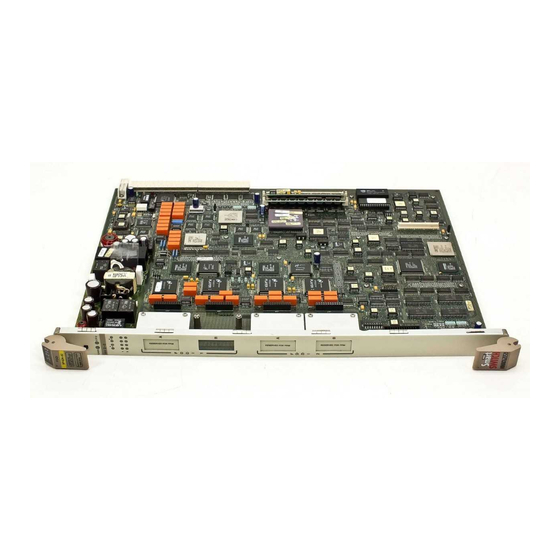
Chapter 1 Introduction ® The 9F426-02 FDDI SmartSwitch Module shown in Figure 1-1, is a three port switch module with two front panel FDDI interfaces and one INB-2 backplane interface. The external FDDI networks are connected to the module using standard Cabletron FPIMs on the front panel. - Page 12 Introduction Management The 9F426-02 module has two full implementations of SMT (Version 7.3), one per interface, and SNMP for local and remote management. Local management is provided through the RS-232 COM ports on the SmartSwitch 9000 Environmental Module using a standard VT-220 terminal or emulator. Remote management is possible through Cabletron’s SPECTRUM or any SNMP compliant management tool as well as telneting to the module.
- Page 13 Introduction FDDI 9F426-02 Figure 1-1. The 9F426-02 Module...
-
Page 14: Related Manuals
Introduction Related Manuals The manuals listed below should be used to supplement the procedures and technical data contained in this manual. SmartSwitch 9000 Installation Guide SmartSwitch 9000 9C300-1 Environmental Module User’s Guide SmartSwitch 9000 9C214-1 AC Power Supply User’s Guide INB Terminator Modules Installation Guide SmartSwitch 9000 Module Local Management User’s Guide Getting Help... -
Page 15: Installing The Smartswitch 9000 Module
Chapter 2 Installing the SmartSwitch 9000 Module This module uses FPIMs for the front panel connections. They are not shipped with the module and must be purchased separately. For more information on FPIMs see Appendix A. Unpacking the Module 1. Carefully remove the module from the shipping box. (Save the box and packing materials in the event the module must be reshipped.) 2. -
Page 16: User-Accessible Components
Installing the SmartSwitch 9000 Module Figure 2-1. Installing an FPIM User-Accessible Components Figure 2-2 shows the various components that are accessible to the user. These consist of an eight-position DIP switch (explained below), replaceable PROMs and sockets for RAM. These will be used for future upgrades. Instructions for installing the components will be supplied with the upgrade kit. - Page 17 Installing the SmartSwitch 9000 Module SMB-1 PROM Local DRAM Socket Flash SIMM Socket i960 Processor Boot PROM DIP Switch Figure 2-2. User Accessible Components An eight-position DIP switch is located on the module card as shown in Figure 2-2. The function of the switches are listed in Table 2-1.
- Page 18 Installing the SmartSwitch 9000 Module See the Cautions at the end of this table. Table 2-1. Function of DIP Switch Switch Function Description When toggled, this switch clears user-entered Clear passwords stored in NVRAM, and restores the Password default passwords. Once reset you can use the defaults or enter new passwords.
-
Page 19: Installing The Module Into The Smartswitch 9000 Chassis
Installing the SmartSwitch 9000 Module Installing the Module into the SmartSwitch 9000 Chassis To install the SmartSwitch 9000 module, follow the steps below: The INB Terminator Modules must be installed on the rear of the chassis before NOTE powering up this module. Refer to the INB Terminator Modules Installation Guide for information and installation procedure. - Page 20 Installing the SmartSwitch 9000 Module Plastic Tab Jack for ESD Wrist Strap Metal Back-Panel Module Module Guides Warning: Ensure that the circuit card is between the card guides. Lock down the top and bottom plastic tabs at the same time, applying even pressure. Figure 2-3.
-
Page 21: The Reset Switch
Installing the SmartSwitch 9000 Module The Reset Switch The Reset switch is located under the top plastic tab as shown in Figure 2-4. It serves two functions: • Pressing the reset switch twice within three seconds causes the processor (i960) to reset. - Page 22 Installing the SmartSwitch 9000 Module...
-
Page 23: Chapter 3 Operation
Chapter 3 Operation The 9F426-02 module is capable of switching any three, of five possible interfaces, depending on how it is configured. The INB-2 connection is always fixed. When configuring the module, the decision is made to connect both front panel ports, both FNB ports, or one front panel and one FNB port to the traditional switch. -
Page 24: System Management Buses
Operation System Management Buses There are two management channels within the SmartSwitch 9000 system: the SMB-1 and the SMB-10. These buses provide out-of-band management and inter- module management communication. SMB-1 Bus The SMB-1 is a 1Mbs management bus located within the SmartSwitch 9000. This bus is utilized by all diagnostic controllers in the system including connectivity modules, power supply modules and the environmental module. -
Page 25: Dc/Dc Converter
Operation DC/DC Converter The DC/DC converter converts the 48 VDC on the system power bus to the necessary operating voltages for its host network services module. The diagnostic controller monitors and controls the operation of the DC/DC converter. INB Interface Each module that attaches to the INB has an INB Network Interface Block (NIB). -
Page 26: I960 Core
Operation i960 Core The i960 core provides the SNMP protocol stacks, to support industry-standard MIBs. Additionally, Cabletron enterprise extension MIBs are supported for each media type. Advanced management services, such as the Distributed LAN Monitor, telnet and network address to MAC address mapping, are also provided by the i960 core. -
Page 27: Lanview Leds
Chapter 4 LANVIEW LEDs The front panel LANVIEW LEDs indicate the status of the module and may be used as an aid in troubleshooting. Shown in Figure 4-1 is the LANVIEW LEDs of the 9F426-02 module. FDDI 9F426-02 System Status INB Receive INB Transmit FDDI Receive... - Page 28 LANVIEW LEDs The functions of the two System Status LEDs, System Management Bus (SMB) and the CPU, are listed in Table 4-1. Table 4-1. System Status (SMB and CPU) LEDs LED Color State Description Green Functional Fully operational. Yellow Crippled Not fully operational (i.e., one bad port).
- Page 29 LANVIEW LEDs The function of the FDDI receive LEDs is listed in Table 4-4. Table 4-4. FDDI Receive LEDs LED Color State Yellow (Flashing) Activity No Activity The function of the FDDI Transmit LED is listed in Table 4-5. Table 4-5. FDDI Transmit LEDs LED Color State Green (Flashing)
- Page 30 LANVIEW LEDs The functions of the FDDI Status LEDs are listed in Table 4-6. Table 4-6. FDDI Status LEDs STATE Green Green Ports Enabled & Active Green Green Green THRU A, MAC on Primary, Secondary Bypasses Board Green Green Green THRU B, MAC on Secondary, Primary Bypasses Board Green...
-
Page 31: Chapter 5 Specifications
Chapter 5 Specifications Technical Specifications Intel i960 RISC based microprocessor Memory 4 Meg. Local RAM (expandable to 12 Meg.) 4 Meg. Flash Memory (expandable to 16 Meg.) 16 Meg. DRAM 2 Meg. Packet RAM Standards ANSI FDDI X3T9.5 MMF-PMD SMF-PMD Network Interface Cabletron FPIMs... -
Page 32: Safety
Specifications Safety It is the responsibility of the person who sells the system to which the module will be a part to ensure that the total system meets allowed limits of conducted and radiated emissions. CAUTION This equipment meets the safety requirements of: •... - Page 33 Appendix A FPIM Specifications This SmartSwitch 9000 module uses Fiber Port Interface Modules (FPIM) to provide front panel cable connections. The FPIMs are user-installable. See section titled on page 2-1. Installing an FPIM FPIM-00 and FPIM-01 The FPIM-00 and FPIM-01 provide a multimode fiber connection. The FPIM-00 uses a MIC-style connector and the FPIM-01 uses an SC-type connector.
- Page 34 FPIM Specifications Transmitter power parameters are listed in Table A-2. Table A-2. Transmitter Power Parameters Worst Worst Case Typical Parameter Typical Value Case Budget Budget 50/125 µm fiber -13.0 dBm -15.0 dBm 13.0 dB 17.5 dB 62.5/125 µm fiber -10.0 dBm -12.0 dBm 16.0 dB 20.5 dB...
- Page 35 FPIM-05 and FPIM-07 FPIM-05 and FPIM-07 The FPIM-05 and FPIM-07 provide a single-mode fiber connection. The FPIM-05 uses a MIC-style connector and the FPIM-07 uses an SC-type connector. The specifications for both devices are listed in Table A-4. Table A-4. FPIM-05 and FPIM-07 Specifications Parameter Typical Minimum...
- Page 36 FPIM Specifications...
Need help?
Do you have a question about the 9F426-02 and is the answer not in the manual?
Questions and answers