
Related Manuals for 3Com 3CRWE876075


Summary of Contents for 3Com 3CRWE876075
-
Page 1: User Guide
User Guide 3Com Wireless 8760 Dual-radio 11a/b/g PoE Access Point 3CRWE876075 / WL-546 www.3Com.com Part Number 10015153 Rev. AA Published June, 2006... - Page 2 01752-3064 Copyright © 2006 3Com Corporation. All rights reserved. No part of this documentation may be reproduced in any form or by any means or used to make any derivative work (such as translation, transformation, or adaptation) without written permission from 3Com Corporation.
-
Page 3: Table Of Contents
Contents Introduction Product Features Security Performance and Reliability Virtual Access Point (VAP) Support WDS Bridging and Spanning Tree Protocol (STP) Support Manageability Wireless Network Standards 802.11g 802.11a Approved Channels Installing the Access Point Installation Requirements Power Requirements Safety Information Deciding Where to Place Equipment and Performing A Site Survey Before You Begin Connecting the Standard Antennas... -
Page 4: Table Of Contents
Initial Configuration Networks with a DHCP Server Networks without a DHCP Server Using the 3Com Installation CD Launch the 3COM Wireless Infrastructure Device Manager (Widman) utility Launching the 3com Wireless Interface Device Manager First Time Only Using the Setup Wizard... -
Page 5: Table Of Contents
Wi-Fi Protected Access (WPA) 4-56 Command Line Interface Using the Command Line Interface Accessing the CLI Console Connection Telnet Connection Entering Commands Keywords and Arguments Minimum Abbreviation Command Completion Getting Help on Commands Showing Commands Partial Keyword Lookup Negating the Effect of Commands Using Command History Understanding Command Modes Exec Commands... - Page 7 ERMINOLOGY Access Point—An internetworking device that seamlessly connects wired and wireless networks. Ad Hoc—An ad hoc wireless LAN is a group of computers, each with wireless adapters, connected as an independent wireless LAN. Backbone—The core infrastructure of a network. The portion of the network that transports information from one central location to another central location where it is unloaded onto a local system.
- Page 8 VAP—Virtual Access Point. An access point radio capable of operating as four separate access points. VLAN—Virtual Local Area Network. A LAN consisting of groups of hosts that are on physically different segments but that communicate as though they were on the same segment. WEP—Wired Equivalent Privacy is based on the use of security keys and the popular RC4 encryption algorithm.
- Page 9 NTRODUCTION The 3Com® Wireless 8760 Dual-radio 11a/b/g PoE Access Point offers a dual-mode architecture that supports 802.11g, 802.11a, and 802.11b wireless users on a single device. This means you can mix and match radio bands to meet different coverage and bandwidth needs within the same area.
- Page 10 256 simultaneous users. The access point supports two radios and external antennas including WDS bridging ability on both radios. ECURITY 3Com offers one of the most robust suite of standards-based security on the market today. To protect sensitive data broadcast over the wireless LAN, 3Com supports WPA and WPA2 security standards.
-
Page 11: Product Features
Product Features ERFORMANCE AND ELIABILITY 3Com wireless access point performance features ensure reliable and seamless connections for users wherever they roam: Automatic channel selection automatically finds the least loaded channel for interference-free communication. Auto network connect and dynamic rate shifting keep users connected through a wide variety of conditions by changing to the optimum connection speed as they move through the network. - Page 12 1: I HAPTER NTRODUCTION ANAGEABILITY 3Com offers a wide range of standards-based management support, from SNMP to 3Com Network Supervisor and HP OpenView for seamless integration with your wired network. Wireless Infrastructure Device Manager lets you configure parameters, run diagnostics, backup and restore configurations, and monitor performance from anywhere on the network using an embedded web server browser.
-
Page 13: Wireless Network Standards
For proper installation, select your country from the country selection list. To conform to FCC and other country restrictions your product may be limited in the channels that are available. If other channels are permitted in your country please visit the 3Com website for the latest software version. - Page 14 1: I HAPTER NTRODUCTION...
- Page 15 Standard category 5 straight (8-wire) Ethernet cable. The cable must be long enough to reach the power supply or the power-over-Ethernet LAN port. If you use the 3Com power supply, you need an additional Ethernet cable to connect the access point to the LAN.
- Page 16 The access point complies with the IEEE 802.3af power-over-Ethernet standard. It receives power over standard category 5 straight (8-wire) Ethernet cable. Installation requires the use of either the 3Com power supply provided or IEEE 802.3af compliant power supply equipment (output power rated 48 V dc @ 400 mA maximum).
- Page 17 Deciding Where to Place Equipment and Performing A Site Survey CAUTION: The 3Com power supply input relies on a 16A rated building fuse or circuit protector for short circuit protection of the line to neutral conductors. CAUTION: It is the responsibility of the installer to ensure that the Power-over-Ethernet (POE) power supply is properly connected.
- Page 18 CCESS OINT Configuring a wireless LAN can be as easy as placing a 3Com Wireless Access Point in a central area and making the necessary connections to the AP and the clients. However, installing multiple Access Points may require more planning.
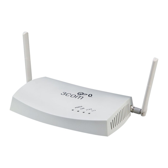
- Page 19 Connecting the Standard Antennas Figure 1 Front and Rear Panel Description Kensington Lock Slot LEDs POE Port Console Port ONNECTING THE TANDARD NTENNAS The Access Point 8760 is supplied with standard detachable antennas. These should be attached before the access point is installed. If using an alternate antenna, see “Selecting and Connecting a Different Antenna Model”...
- Page 20 5 straight (8-wire) Ethernet cable. There are two ways to supply power to the access point: Use the 3Com Integrated Power-over-Ethernet power supply. In this case, you need to supply a second Ethernet cable to connect to the wired LAN.
- Page 21 Connecting Power If you supply your own Ethernet cable for connecting power, be sure that it is standard category 5 straight-through (8-wire) cable that has not been altered in any way. Use of nonstandard cable could damage the access point. Figure 3 Connecting Power...
- Page 22 If your LAN equipment complies with the IEEE 802.3af power-over-Ethernet standard, you can connect the access point directly to a LAN port. For example, the illustration above right shows a connection through a 3Com Ethernet Power Supply to a 3Com Switch.
- Page 23 Checking the LEDs HECKING THE When power is connected, the access point LEDs light. The illustration and the following table describe the LEDs and their functions. Table 1 System LEDs Color Indicates Power Green The access point is powered up and operating normally.
- Page 24 2: I HAPTER NSTALLING THE CCESS OINT EILING LECTRICAL OUNTING To mount the access point to a wall, ceiling, or electrical box: Remove the access point from the mounting bracket. Screw the mounting bracket to a wall, ceiling, or electrical box (NEMA enclosure): If mounting to a solid surface wall or ceiling, use two of the sheet metal screws and two of the wall anchors (included).
- Page 25 Wall, Ceiling, or Electrical Box Mounting Figure 4 Routing a Cable Routing a cable Figure 5 Mounting Bracket Installing the mounting bracket Connect the Ethernet cable to the port on the back of the access point. 2-11...
- Page 26 The standard detachable antennas supplied with the Access Point are suitable for a broad variety of environments. If you require a different type of antenna for the Access Point, several options are available by model number from the 3Com Web site (www.3Com.com).
- Page 27 Selecting and Connecting a Different Antenna Model Figure 7 Connecting Antennae Side Side Position the antenna so that there are minimal obstacles between it and any client with which it will communicate. While maintaining a direct line of sight between the antenna and a client is not strictly necessary, such an arrangement helps to ensure a strong signal.
- Page 28 As an optional FTP Server. To install a tool from the CD: Power up the computer and put the 3Com CD in the CD-ROM drive. The setup menu should appear when the CD autostarts. If no menu appears, you can run the setup.exe startup program from the Windows Start menu.
-
Page 29: I Nitial C Onfiguration
AP. It takes between one and two minutes for the Access Point to determine if there is a DHCP server on the network. Use the 3Com Wireless Infrastructure Device Manager (Widman) included on the 3Com Installation CD to locate the Access Point on the network and view its IP address. - Page 30 Login name: admin Password: password If the Configuration Management System does not start, the Access Point is on a different subnet than the computer. Install and start the 3Com Wireless Infrastructure Device Manager to discover the Access Point’s IP address. SING THE...
- Page 31 Figure 8 Wireless Interface Device Manager Click on the Properties button to see the following screen Figure 9 Wireless Interface Device Manager - Properties...
- Page 32 Unless it detects a DHCP server on the network, the access point uses Auto IP to assign an IP address of the form 169.254.2.1. Use the 3Com Wireless Infrastructure Device Manager to locate 3Com Wireless LAN devices and launch their configurations. When installing the device manager, make sure the computer is connected to the same network as the device to be configured.
-
Page 33: Using The Setup Wizard
Using the Setup Wizard NOTE: If you changed the default IP address via the command line interface above, use that address instead of the one shown here. Logging In – Enter the username “admin,” and password “password,” then click LOGIN. For information on configuring a user name and password, see page 4-22. - Page 34 3: I HAPTER NITIAL ONFIGURATION The home page displays the Main Menu. Figure 11 Home Page Launching the Setup Wizard – To perform initial configuration, click Setup Wizard on the home page, select the VAP you wish to configure, then click on the [Next] button to start the process.
- Page 35 Using the Setup Wizard Service Set ID – Enter the service set identifier in the SSID box which all wireless clients must use to associate with the access point. The SSID is case sensitive and can consist of up to 32 alphanumeric characters. Figure 13 Setup Wizard - Step 1 Radio Channel –...
- Page 36 3: I HAPTER NITIAL ONFIGURATION Figure 14 Setup Wizard - Step 2 802.11a Turbo Mode – If you select Enable, the access point will operate in turbo mode with a data rate of up to 108 Mbps. Normal mode support 13 channels, Turbo mode supports only 5 channels.
- Page 37 Using the Setup Wizard IP Configuration – Either enable or disable Dynamic Host Configuration Protocol (DHCP) for automatic IP configuration. If you disable DHCP, then manually enter the IP address and subnet mask. If a management station exists on another network segment, then you must enter the IP address for a gateway that can route traffic between these segments.
- Page 38 3: I HAPTER NITIAL ONFIGURATION Figure 16 Setup Wizard - Step 4 Authentication Type – Use “Open System” to allow open access to all wireless clients without performing authentication, or “Shared Key” to perform authentication based on a shared key that has been distributed to all stations. (Default: Open System) WEP –...
- Page 39 Using the Setup Wizard Click Finish. Click the OK button to complete the wizard. Figure 17 Setup Wizard - Completed 3-11...
- Page 40 3: I HAPTER NITIAL ONFIGURATION 3-12...
- Page 41 For a new access point installation, the default WLAN Service Area (ESSID) is 3Com and no security is set. Unless it detects a DHCP server on the network, the access point uses Auto IP to assign an IP address of the form 169.254.2.1.
-
Page 42: Advanced Setup
4: S HAPTER YSTEM ONFIGURATION Figure 18 Advanced Setup The information in this chapter is organized to reflect the structure of the web screens for easy reference. However, it is recommended that you configure a user name and password as the first step under Administration to control management access to this device (page 4-22). - Page 43 Advanced Setup Menu Description Page SNMP Configures SNMP settings 4-18 Administration Configures user name and password for management access; 4-22 upgrades software from local file, FTP or TFTP server; resets configuration settings to factory defaults; and resets the access point WDS/STP Settings Configures WDS bridging and Spanning Tree Protocol features 4-27...
-
Page 44: System Identification
4: S HAPTER YSTEM ONFIGURATION YSTEM DENTIFICATION The system name for the access point can be left at its default setting. However, modifying this parameter can help you to more easily distinguish different devices in your network. Figure 19 System Identification System Name –... -
Page 45: Tcp / Ip Settings
IP address that is reachable through your network. By default, the access point will be automatically configured with IP settings from a Dynamic Host Configuration Protocol (DHCP) server. Use 3Com Wireless Infrastructure Device Manager to discover or set the initial IP address of the unit. - Page 46 4: S HAPTER YSTEM ONFIGURATION DHCP Client (Enable) – Select this option to obtain the IP settings for the access point from a DHCP (Dynamic Host Configuration Protocol) server. The IP address, subnet mask, default gateway, and Domain Name Server (DNS) address are dynamically assigned to the access point by the network DHCP server.
- Page 47 TCP / IP Settings Figure 21 Smart Monitor By enabling Smart Monitor (known as Link Integrity in the CLI) and setting a target IP address, the AP will periodically (set by the ping interval) check to see if the target address responds to pings. If it fails to respond to a ping after the configured number of retries, it will disable both radios so that no clients can connect to the AP.
-
Page 48: Radius
4: S HAPTER YSTEM ONFIGURATION RADIUS Remote Authentication Dial-in User Service (RADIUS) is an authentication protocol that uses software running on a central server to control access to RADIUS-aware devices on the network. An authentication server contains a database of user credentials for each user that requires access to the network. -
Page 49: Authentication
Authentication Port: The UDP port number used by the RADIUS server for authentication messages. (Range: 1024-65535; Default: 1812) Key: A shared text string used to encrypt messages between the access point and the RADIUS server. Be sure that the same text string is specified on the RADIUS server. - Page 50 4: S HAPTER YSTEM ONFIGURATION use both MAC address and 802.1X authentication, with client station MAC authentication occurring prior to IEEE 802.1X authentication. However, it is better to choose one or the other, as appropriate. IEEE 802.1X is a standard framework for network access control that uses a central RADIUS server for user authentication.
- Page 51 Authentication Figure 23 Authentication MAC Authentication – You can configure a list of the MAC addresses for wireless clients that are authorized to access the network. This provides a basic level of authentication for wireless clients attempting to gain access to the network. A database of authorized MAC addresses can be stored locally on the access point or remotely on a central RADIUS server.
- Page 52 4: S HAPTER YSTEM ONFIGURATION Local MAC: The MAC address of the associating station is compared against the local database stored on the access point. Use the Local MAC Authentication section of this web page to set up the local database, and configure all access points in the wireless network service area with the same MAC address database.
- Page 53 Authentication When 802.1X is enabled, the broadcast and session key rotation intervals can also be configured. Broadcast Key Refresh Rate: Sets the interval at which the broadcast keys are refreshed for stations using 802.1X dynamic keying. (Range: 0-1440 minutes; Default: 0 means disabled) Session Key Refresh Rate: The interval at which the access point refreshes unicast session keys for associated clients.
-
Page 54: Filter Control
4: S HAPTER YSTEM ONFIGURATION ILTER ONTROL The access point can employ network traffic frame filtering to control access to network resources and increase security. You can prevent communications between wireless clients and prevent access point management from wireless clients. Also, you can block specific Ethernet traffic from being forwarded by the access point. - Page 55 Filter Control AP Management Filter – Controls management access to the access point from wireless clients. Management interfaces include the web, Telnet, or SNMP. (Default: Disabled) Disabled: Allows management access from wireless clients. Enabled: Blocks management access from wireless clients. Uplink Port MAC Address Filtering Status –...
-
Page 56: Vlan
4: S HAPTER YSTEM ONFIGURATION VLAN The access point can employ VLAN tagging support to control access to network resources and increase security. VLANs separate traffic passing between the access point, associated clients, and the wired network. There can be a VLAN assigned to each associated client, a default VLAN for each VAP (Virtual Access Point) interface, and a management VLAN for the access point. - Page 57 Filter Control A VLAN ID (1-4094) can be assigned to a client after successful IEEE 802.1X authentication. The client VLAN IDs must be configured on the RADIUS server for each user authorized to access the network. If a client does not have a configured VLAN ID on the RADIUS server, the access point assigns the client to the configured default VLAN ID for the VAP interface.
-
Page 58: Snmp
4: S HAPTER YSTEM ONFIGURATION SNMP Simple Network Management Protocol (SNMP) is a communication protocol designed specifically for managing devices on a network. Equipment commonly managed with SNMP includes switches, routers and host computers. SNMP is typically used to configure these devices for proper operation in a network environment, as well as to monitor them to evaluate performance or detect potential problems. - Page 59 SNMP Figure 26 SNMP SNMP – Enables or disables SNMP management access and also enables the access point to send SNMP traps (notifications). (Default: Disable) Location – A text string that describes the system location. (Maximum length: 255 characters) Contact – A text string that describes the system contact. (Maximum length: 255 characters) Community Name (Read Only) –...
- Page 60 4: S HAPTER YSTEM ONFIGURATION Trap Destination Community Name – The community string sent with the notification operation. (Maximum length: 23 characters, case sensitive; Default: public) Engine ID – Sets the engine identifier for the SNMPv3 agent that resides on the access point.
-
Page 61: Configuring Snmpv3 Users
SNMP dot11InterfaceAFail - The 802.11a or 802.11g interface has failed. dot1xMacAddrAuthSuccess - A client station has successfully authenticated its MAC address with the RADIUS server. dot1xMacAddrAuthFail - A client station has failed MAC address authentication with the RADIUS server. dot1xAuthNotInitiated - A client station did not initiate 802.1X authentication. dot1xAuthSuccess - A 802.1X client station has been successfully authenticated by the RADIUS server. -
Page 62: Administration
4: S HAPTER YSTEM ONFIGURATION Passphrase – The password or key associated with the authentication and privacy settings. A minimum of eight plain text characters is required. Action – Click the Add button to add a new user to the list. Click the edit button to change details of an existing user. -
Page 63: Telnet And Ssh Settings
Administration Figure 29 Administration Username – The name of the user. The default name is “admin.” (Length: 3-16 characters, case sensitive) New Password – The password for management access. (Length: 3-16 characters, case sensitive) Confirm New Password – Enter the password again for verification. SSH S ELNET AND ETTINGS... - Page 64 4: S HAPTER YSTEM ONFIGURATION Telnet Server: Enables or disables the Telnet server. (Default: Disabled) SSH Server: Enables or disables the SSH server. (Default: Enabled) SSH Port Number: Sets the UDP port for the SSH server. (Range: 1-65535; Default: 22) PGRADING IRMWARE You can upgrade new access point software from a local file on the management...
- Page 65 Administration Figure 31 Firmware Upgrade Before upgrading new software, verify that the access point is connected to the network and has been configured with a compatible IP address and subnet mask. If you need to download from an FTP or TFTP server, take the following additional steps: Obtain the IP address of the FTP or TFTP server where the access point software is stored.
- Page 66 New firmware file: Specifies the name of the code file on the server. The device will only accept firmware files named “3Com-img.bin”. Firmware Upgrade Remote – Downloads an operation code image file from a specified remote FTP or TFTP server. After filling in the following fields, click Start Upgrade to proceed.
-
Page 67: Wds And Spanning Tree Settings
WDS and Spanning Tree Settings NOTE: If you have upgraded system software, then you must reboot the access point to implement the new operation code. New software that is incompatible with the current configuration automatically restores the access point to default values when first activated after a reboot. - Page 68 4: S HAPTER YSTEM ONFIGURATION Figure 32 WDS and Spanning Tree Settings 4-28...
- Page 69 WDS and Spanning Tree Settings WDS Bridge – Up to six WDS bridge or repeater links (MAC addresses) per radio interface can be specified for each unit in the wireless bridge network. One unit only must be configured as the “root bridge” in the wireless network. The root bridge is the unit connected to the main core of the wired LAN.
- Page 70 4: S HAPTER YSTEM ONFIGURATION Figure 33 Spanning Tree Protocol Spanning Tree Protocol – STP uses a distributed algorithm to select a bridging device (STP-compliant switch, bridge or router) that serves as the root of the spanning tree network. It selects a root port on each bridging device (except for the root device) which incurs the lowest path cost when forwarding a packet 4-30...
- Page 71 WDS and Spanning Tree Settings from that device to the root device. Then it selects a designated bridging device from each LAN which incurs the lowest path cost when forwarding a packet from that LAN to the root device. All ports connected to designated bridging devices are assigned as designated ports.
- Page 72 4: S HAPTER YSTEM ONFIGURATION Bridge Forwarding Delay – The maximum time (in seconds) this device waits before changing states (i.e., discarding to learning to forwarding). This delay is required because every device must receive information about topology changes before it starts to forward frames. In addition, each port needs time to listen for conflicting information that would make it return to a discarding state;...
-
Page 73: System Log
System Log YSTEM The access point can be configured to send event and error messages to a System Log Server. The system clock can also be synchronized with a time server, so that all the messages sent to the Syslog server are stamped with the correct time and date. - Page 74 4: S HAPTER YSTEM ONFIGURATION Enter Time Zone – Sets the desired time zone + or - GMT. Enable Daylight Saving – Adjusts the clock for summertime and wintertime. The system allows you to limit the messages that are logged by specifying a minimum severity level.
-
Page 75: Radio Interface
Radio Interface Secondary Server: The IP address of a secondary SNTP or NTP time server. The access point first attempts to update the time from the primary server; if this fails it attempts an update from the secondary server. NOTE: The access point also allows you to disable SNTP and set the system clock manually. -
Page 76: A Interface
NOTE: The 8760 Access Point ships from the factory enabled only for channels allowed in the US/Canada. If you live in an area where additional channels are allowed, go to the 3Com web site (http://www.3com.com) and download the latest software that will allow additional channels in your country. - Page 77 Radio Interface SSID – The name of the basic service set provided by a VAP interface. Clients that want to connect to the network through the access point must set their SSID to the same as that of an access point VAP interface. (Default: 3Com1 to 3Com4 for 802.11a, 3Com5 to 3Com8 for 802.11b/g;...
- Page 78 4: S HAPTER YSTEM ONFIGURATION ONFIGURING OMMON ADIO ETTINGS To configure common radio settings, select the Radio Settings page, and scroll down to below the VAP radio settings. Figure 36 Radio Settings A Country Code – The current country code setting. This setting restricts operation of the access point to radio channels and transmit power levels permitted for wireless networks in the specified country.
- Page 79 Selecting the correct antenna ID ensures that the access point's radio transmissions are within regulatory power limits for the country of operation. (Default: 3Com Integrated Antenna) 4-39...
- Page 80 (Default: Diversity) Both: The radio uses both antennas in a diversity system. Select this method when the Antenna ID is set to “3Com Integrated Antenna” to use the access point's integrated antennas. Right: The radio only uses the antenna on the right side (the side closest to the access point LEDs).
- Page 81 Radio Interface Delivery Traffic Indication Message (DTIM) – The rate at which stations in sleep mode must wake up to receive broadcast/multicast transmissions. The DTIM interval indicates how often the MAC layer forwards broadcast/multicast traffic, which is necessary to wake up stations that are using Power Save mode.
-
Page 82: Configuring Common Radio Settings
4: S HAPTER YSTEM ONFIGURATION 802.11 NTERFACE The IEEE 802.11g standard operates within the 2.4 GHz band at up to 54 Mbps. Also note that because the IEEE 802.11g standard is an extension of the IEEE 802.11b standard, it allows clients with 802.11b wireless network cards to associate to an 802.11g access point. - Page 83 Radio Interface Figure 37 Radio Settings B/G Client Access Mode – Selects the operating mode for the 802.11g wireless interface. (Default: 802.11b+g) 802.11b+g: Both 802.11b and 802.11g clients can communicate with the access point (up to 54 Mbps). 802.11b only: Both 802.11b and 802.11g clients can communicate with the access point, but 802.11g clients can only transfer data at 802.11b standard rates (up to 11 Mbps).
- Page 84 4: S HAPTER YSTEM ONFIGURATION Super Mode – The Atheros proprietary Super G performance enhancements are supported by the access point. These enhancements include bursting, compression, fast frames and dynamic turbo. Maximum throughput ranges between 40 to 60 Mbps for connections to Atheros-compatible clients. (Default: Disabled) Radio Channel –...
- Page 85 Radio Interface The access point implements QoS using the Wi-Fi Multimedia (WMM) standard. Using WMM, the access point is able to prioritize traffic and optimize performance when multiple applications compete for wireless network bandwidth at the same time. WMM employs techniques that are a subset of the developing IEEE 802.11e QoS standard and it enables the access point to inter operate with both WMMenabled clients and other devices that may lack any WMM functionality.
- Page 86 4: S HAPTER YSTEM ONFIGURATION resolution mechanism first selects data with the highest priority to be granted a transmit opportunity. Then the same collision resolution mechanism is used externally to determine which device has access to the wireless medium. For each AC queue, the collision resolution mechanism is dependent on two timing parameters: AIFSN (Arbitration Inter-Frame Space Number), a number used to calculate the minimum time between data frames...
- Page 87 Radio Interface Figure 39 WMM Configuration WMM – Sets the WMM operational mode on the access point. When enabled, the parameters for each AC queue will be employed on the access point and QoS capabilities are advertised to WMM-enabled clients. (Default: Support) Disable: WMM is disabled.
- Page 88 4: S HAPTER YSTEM ONFIGURATION initial wait time is a random value between zero and the CWMin value. Specify the CWMin value in the range 0-15 microseconds. Note that the CWMin value must be equal or less than the CWMax value. logCWMax (Maximum Contention Window) –...
-
Page 89: Security
Security ECURITY The access point is configured by default as an “open system,” which broadcasts a beacon signal including the configured SSID. Wireless clients with an SSID setting of “any” can read the SSID from the beacon and automatically set their SSID to allow immediate connection to the nearest access point. - Page 90 4: S HAPTER YSTEM ONFIGURATION Security Client Support Implementation Considerations Mechanism WPA over 802.1X Requires WPA-enabled system • Provides robust security in WPA-only mode Mode and network card driver (i.e., WPA clients only) (native support provided in • Offers support for legacy WEP clients, but with Windows XP) increased security risk (i.e., WEP authentication keys disabled)
- Page 91 Security Client Security RADIUS Configuration Summary Combination Authentication Server Dynamic WEP Authentication: Open System Local, RADIUS, or (802.1x) only Encryption: Enable Disabled 802.1x: Required Set 802.1x key refresh and reauthentication rates 802.1x WPA only Authentication: WPA Local only Encryption: Enable WPA Configuration: Required Cipher Suite: TKIP 802.1x: Required...
-
Page 92: Wired Equivalent Privacy (Wep)
4: S HAPTER YSTEM ONFIGURATION Client Security RADIUS Configuration Summary Combination Authentication Server 802.1x WPA-WPA2 Authentication: WPA-WPA2-mixed Local or Disabled Mixed Mode Encryption: Enable WPA Configuration: Required Cipher Suite: TKIP 802.1x: Required Set 802.1x key refresh and reauthentication rates WPA-WPA2 Mixed Authentication: WPA-WPA2-PSK-mixed Local or Disabled Mode Pre-Shared Key... - Page 93 Security Note that all clients share the same keys, which are used for user authentication and data encryption. Up to four keys can be specified. These four keys are used for all VAP interfaces on the same radio. To set up WEP shared keys, click Radio Settings under 802.11a or 802.11b/g, then select Authentication ‘Shared’.
- Page 94 4: S HAPTER YSTEM ONFIGURATION Encryption – Enable or disable the access point to use data encryption (WEP, TKIP, or AES). If this option is selected when using static WEP keys, you must configure at least one key on the access point and all clients. (Default: Disabled) NOTE: You must enable data encryption through the web or CLI in order to enable all types of encryption (WEP, TKIP, or AES) in the access point.
- Page 95 Security Alphanumeric: Enter keys as 5 alphanumeric characters for 64 bit keys, 13 alphanumeric characters for 128 bit keys, or 16 alphanumeric characters for 152 bit keys (802.11a radio only). Key – Selects the key number to use for encryption for each VAP interface. If the clients have all four keys configured to the same values, you can change the encryption key to any of the four settings without having to update the client keys.
-
Page 96: Wi-Fi Protected Access (Wpa)
4: S HAPTER YSTEM ONFIGURATION • Hexadecimal: Enter keys as 10 hexadecimal digits (0-9 and A-F) for 64 bit keys, 26 hexadecimal digits for 128 bit keys, or 32 hexadecimal digits for 152 bit keys (802.11a radio only). This is the default setting. •... - Page 97 Security Temporal Key Integrity Protocol (TKIP): WPA specifies TKIP as the data encryption method to replace WEP. TKIP avoids the problems of WEP static keys by dynamically changing data encryption keys. Basically, TKIP starts with a master (temporal) key for each user session and then mathematically generates other keys to encrypt each data packet.
- Page 98 4: S HAPTER YSTEM ONFIGURATION for WPA2. However, the computational intensive operations of AES-CCMP requires hardware support on client devices. Therefore to implement WPA2 in the network, wireless clients must be upgraded to WPA2-compliant hardware. WPA2 Mixed-Mode: WPA2 defines a transitional mode of operation for networks moving from WPA security to WPA2.
-
Page 99: Status Information
Security Status Information The Status page includes information on the following items: Access Point Status The AP Status window displays basic system configuration settings, as well as the settings for the wireless interface. Figure 43 AP Status AP System Configuration – The AP System Configuration table displays the basic system configuration settings: System Up Time: Length of time the management agent has been up. - Page 100 4: S HAPTER YSTEM ONFIGURATION HTTP Server: Shows if management access via HTTP is enabled. HTTP Server Port: Shows the TCP port used by the HTTP interface. Version: Shows the software version number. 802.1X: Shows if IEEE 802.1X access control for wireless clients is enabled. AP Wireless Configuration –...
- Page 101 Security system” and “shared key.” Open-system authentication accepts any client attempting to connect to the access point without verifying its identity. The shared-key approach uses Wired Equivalent Privacy (WEP) to verify client identity by distributing a shared key to stations before attempting authentication.
- Page 102 4: S HAPTER YSTEM ONFIGURATION Error Messages – An example of a logged error message is: “Station Failed to authenticate (unsupported algorithm).” This message may be caused by any of the following conditions: Access point was set to “Open Authentication”, but a client sent an authentication request frame with a “Shared key.”...
- Page 103 OMMAND NTERFACE SING THE OMMAND NTERFACE CCESSING THE When accessing the management interface for the over a direct connection to the console port, or via a Telnet connection, the access point can be managed by entering command keywords and parameters at the prompt. Using the access point’s command-line interface (CLI) is very similar to entering commands on a UNIX system.
-
Page 104: Telnet Connection
5: C HAPTER OMMAND NTERFACE Telnet Connection Telnet operates over the IP transport protocol. In this environment, your management station and any network device you want to manage over the network must have a valid IP address. Valid IP addresses consist of four numbers, 0 to 255, separated by periods. -
Page 105: Using The Command Line Interface
Using the Command Line Interface NTERING OMMANDS This section describes how to enter CLI commands. Keywords and Arguments A CLI command is a series of keywords and arguments. Keywords identify a command, and arguments specify configuration parameters. For example, in the command “show interfaces ethernet,”... -
Page 106: Showing Commands
5: C HAPTER OMMAND NTERFACE Showing Commands If you enter a “?” at the command prompt, the system will display the first level of keywords for the current configuration mode (Exec, Global Configuration, or Interface). You can also display a list of valid keywords for a specific command. For example, the command “show ?”... -
Page 107: Negating The Effect Of Commands
Using the Command Line Interface Negating the Effect of Commands For many configuration commands you can enter the prefix keyword “no” to cancel the effect of a command or reset the configuration to the default value. For example, the logging command will log system messages to a host server. To disable logging, specify the no logging command. -
Page 108: Configuration Commands
5: C HAPTER OMMAND NTERFACE Configuration Commands Configuration commands are used to modify access point settings. These commands modify the running configuration and are saved in memory. The configuration commands are organized into four different modes: • Global Configuration (GC) - These commands modify the system level configuration, and include commands such as username and password. -
Page 109: Command Groups
Using the Command Line Interface Table 9 Keystroke Commands Keystroke Function Ctrl-A Shifts cursor to start of command line. Ctrl-B Shifts cursor to the left one character. Ctrl-C Terminates a task and displays the command prompt. Ctrl-E Shifts cursor to end of command line. Ctrl-F Shifts cursor to the right one character. -
Page 110: General Commands
5: C HAPTER OMMAND NTERFACE Command Group Description Page WDS Bridge Configures WDS forwarding table settings 5-84 Spanning Tree Configures spanning tree parameters 5-91 Ethernet Interface Configures connection parameters for the Ethernet interface 5-97 Wireless Interface Configures radio interface settings 5-103 Wireless Security Configures radio interface security and encryption settings... - Page 111 Using the Command Line Interface Default Setting None Command Mode Exec Example Enterprise AP#configure Enterprise AP(config)# Related Commands end (5-9) This command returns to the previous configuration mode. Default Setting None Command Mode Global Configuration, Interface Configuration Example This example shows how to return to the Configuration mode from the Interface Configuration mode: Enterprise AP(if-ethernet)#end Enterprise AP(config)#...
- Page 112 5: C HAPTER OMMAND NTERFACE exit This command returns to the Exec mode or exits the configuration program. Default Setting None Command Mode Example This example shows how to return to the Exec mode from the Interface Configuration mode, and then quit the CLI session: Enterprise AP(if-ethernet)#exit Enterprise AP#exit CLI session with the Access Point is now closed...
- Page 113 Using the Command Line Interface - Destination unreachable - The gateway for this destination indicates that the destination is unreachable. - Network or host unreachable - The gateway found no corresponding entry in the route table. • Press <Esc> to stop pinging. Example Enterprise AP#ping 10.1.0.19 192.254.2.19 is alive...
- Page 114 5: C HAPTER OMMAND NTERFACE show history This command shows the contents of the command history buffer. Default Setting None Command Mode Exec Command Usage • The history buffer size is fixed at 10 commands. • Use the up or down arrow keys to scroll through the commands in the history buffer.
-
Page 115: System Management Commands
Using the Command Line Interface System Management Commands These commands are used to configure the user name, password, system logs, browser management options, clock settings, and a variety of other system information. Table 12 System Management Commands Command Function Mode Page Country Setting country... - Page 116 5: C HAPTER OMMAND NTERFACE country This command configures the access point’s country code, which identifies the country of operation and sets the authorized radio channels. Syntax country <country_code> country_code - A two character code that identifies the country of operation.
- Page 117 Using the Command Line Interface Country Code Country Code Country Code Country Code Costa Rica Japan Philippines Yemen Croatia Jordan Poland Venezuela Cyprus Kazakhstan Portugal Vietnam Czech Republic North Korea Puerto Rico Zimbabwe Denmark Korea Slovenia Republic Elsalvador Luxembourg South Africa Default Setting US - for units sold in the United States 99 (no country set) - for units sold in other countries...
- Page 118 5: C HAPTER OMMAND NTERFACE Default Setting Enterprise AP Command Mode Global Configuration Example Enterprise AP(config)#prompt RD2 RD2(config)# system name This command specifies or modifies the system name for this device. Use the no form to restore the default system name. Syntax system name <name>...
- Page 119 Using the Command Line Interface Default Setting admin Command Mode Global Configuration Example Enterprise AP(config)#username bob Enterprise AP(config)# password After initially logging onto the system, you should set the password. Remember to record it in a safe place. Use the no form to reset the default password. Syntax password <password>...
- Page 120 5: C HAPTER OMMAND NTERFACE Command Mode Interface Configuration (Ethernet) Command Usage • The access point supports Secure Shell version 2.0 only. • After boot up, the SSH server needs about two minutes to generate host encryption keys. The SSH server is disabled while the keys are being generated.
- Page 121 Using the Command Line Interface Command Mode Interface Configuration (Ethernet) Example Enterprise AP(if-ethernet)#ip telnet-server enable Enterprise AP(if-ethernet)# ip http port This command specifies the TCP port number used by the web browser interface. Use the no form to use the default port. Syntax ip http port <port-number>...
- Page 122 5: C HAPTER OMMAND NTERFACE Command Mode Global Configuration Example Enterprise AP(config)#ip http server Enterprise AP(config)# Related Commands ip http port (5-19) ip https port Use this command to specify the UDP port number used for HTTPS/SSL connection to the access point’s Web interface. Use the no form to restore the default port.
- Page 123 Using the Command Line Interface ip https server Use this command to enable the secure hypertext transfer protocol (HTTPS) over the Secure Socket Layer (SSL), providing secure access (i.e., an encrypted connection) to the access point’s Web interface. Use the no form to disable this function.
- Page 124 5: C HAPTER OMMAND NTERFACE web-redirect Use this command to enable web-based authentication of clients. Use the no form to disable this function. Syntax [no] web-redirect Default Setting Disabled Command Mode Global Configuration Command Usage • The web redirect feature is used to support billing for a public access wireless network.
- Page 125 Using the Command Line Interface APmgmtIP This command specifies the client IP addresses that are allowed management access to the access point through various protocols. NOTE: Secure Web (HTTPS) connections are not affected by the UI Management or IP Management settings. Syntax APmgmtIP <multiple IP_address subnet_mask | single IP_address | any>...
- Page 126 5: C HAPTER OMMAND NTERFACE Example This example restricts management access to the indicated addresses. Enterprise AP(config)#apmgmtip multiple 192.254.1.50 255.255.255.0 Enterprise AP(config)# APmgmtUI This command enables and disables management access to the access point through SNMP, Telnet and web interfaces. NOTE: Secure Web (HTTPS) connections are not affected by the UI Management or IP Management settings.
- Page 127 Using the Command Line Interface show apmanagement This command shows the AP management configuration, including the IP addresses of management stations allowed to access the access point, as well as the interface protocols which are open to management access. Command Mode Exec Example Enterprise AP#show apmanagement...
-
Page 128: Default Setting
5: C HAPTER OMMAND NTERFACE show system This command displays basic system configuration settings. Default Setting None Command Mode Exec Example Enterprise AP#show system System Information ========================================================== Serial Number : A123456789 System Up time : 0 days, 4 hours, 33 minutes, 29 seconds System Name : Enterprise Wireless AP System Location... -
Page 129: Show Version
Using the Command Line Interface show version This command displays the software version for the system. Command Mode Exec Example Enterprise AP#show version Version Information ========================================= Version: v4.3.2.2 Date : Dec 20 2005, 18:38:12 ========================================= Enterprise AP# show config This command displays detailed configuration information for the system. Command Mode Exec Example... - Page 130 5: C HAPTER OMMAND NTERFACE Protocol Filter Information =========================================================== Local Bridge :DISABLED AP Management :ENABLED Ethernet Type Filter :DISABLED Enabled Protocol Filters ----------------------------------------------------------- No protocol filters are enabled =========================================================== Hardware Version Information =========================================== Hardware version R01A =========================================== Ethernet Interface Information ======================================== IP Address : 192.254.0.151...
- Page 131 Using the Command Line Interface ----------------Security----------------------------------- Closed System : DISABLED Multicast cipher : WEP Unicast cipher : TKIP and AES WPA clients : REQUIRED WPA Key Mgmt Mode : PRE SHARED KEY WPA PSK Key Type : ALPHANUMERIC Encryption : DISABLED Default Transmit Key Static Keys : Key 1: EMPTY...
- Page 132 5: C HAPTER OMMAND NTERFACE Radius Secondary Server Information ======================================== : 0.0.0.0 Port : 1812 : ***** Retransmit Timeout Radius MAC format : no-delimiter Radius VLAN format : HEX ======================================== SNMP Information ============================================== Service State : Disable Community (ro) : ******** Community (rw) : ******** Location...
- Page 133 Using the Command Line Interface SNTP Information =========================================================== Service State : Disabled SNTP (server 1) IP : 137.92.140.80 SNTP (server 2) IP : 192.43.244.18 Current Time : 00 : 14, Jan 1st, 1970 Time Zone : -5 (BOGOTA, EASTERN, INDIANA) Daylight Saving : Disabled ===========================================================...
-
Page 134: Show Hardware
5: C HAPTER OMMAND NTERFACE SSH Server : ENABLED SSH Server Port : 22 Telnet Server : ENABLED WEB Redirect : DISABLED DHCP Relay : DISABLED ============================================================== Version Information ========================================= Version: v4.3.2.2 Date : Dec 20 2005, 18:38:12 ========================================= Enterprise AP# show hardware This command displays the hardware version of the system. - Page 135 Using the Command Line Interface logging on This command controls logging of error messages; i.e., sending debug or error messages to memory. The no form disables the logging process. Syntax [no] logging on Default Setting Disabled Command Mode Global Configuration Command Usage The logging process controls error messages saved to memory.
- Page 136 5: C HAPTER OMMAND NTERFACE Default Setting None Command Mode Global Configuration Example Enterprise AP(config)#logging host 1 10.1.0.3 Enterprise AP(config)# logging console This command initiates logging of error messages to the console. Use the no form to disable logging to the console. Syntax [no] logging console Default Setting...
- Page 137 Using the Command Line Interface Command Usage Messages sent include the selected level down to Emergency level. Level Argument Description Emergency System unusable Alert Immediate action needed Critical Critical conditions (e.g., memory allocation, or free memory error - resource exhausted) Error Error conditions (e.g., invalid input, default used) Warning...
-
Page 138: Logging Clear
5: C HAPTER OMMAND NTERFACE Example Enterprise AP(config)#logging facility 19 Enterprise AP(config)# logging clear This command clears all log messages stored in the access point’s memory. Syntax logging clear Command Mode Global Configuration Example Enterprise AP(config)#logging clear Enterprise AP(config)# show logging This command displays the logging configuration. -
Page 139: System Clock Commands
Using the Command Line Interface show event-log This command displays log messages stored in the access point’s memory. Syntax show event-log Command Mode Exec Example Enterprise AP#show event-log Mar 09 11:57:55 Information: 802.11g:11g Radio Interface Enabled Mar 09 11:57:55 Information: 802.11g:Radio channel updated to 8 Mar 09 11:57:34 Information: 802.11g:11g Radio Interface Enabled Mar 09 11:57:18... - Page 140 5: C HAPTER OMMAND NTERFACE sntp-server ip This command sets the IP address of the servers to which SNTP time requests are issued. Use the this command with no arguments to clear all time servers from the current list. Syntax sntp-server ip <1 | 2>...
- Page 141 Using the Command Line Interface Default Setting Enabled Command Mode Global Configuration Command Usage The time acquired from time servers is used to record accurate dates and times for log events. Without SNTP, the access point only records the time starting from the factory default set at the last bootup (i.e., 00:14:00, January 1, 1970).
- Page 142 5: C HAPTER OMMAND NTERFACE Related Commands sntp-server enable (5-38) sntp-server daylight-saving This command sets the start and end dates for daylight savings time. Use the no form to disable daylight savings time. Syntax [no] sntp-server daylight-saving Default Setting Disabled Command Mode Global Configuration Command Usage...
- Page 143 Using the Command Line Interface Command Mode Global Configuration Command Usage This command sets the local time zone relative to the Coordinated Universal Time (UTC, formerly Greenwich Mean Time or GMT), based on the earth’s prime meridian, zero degrees longitude. To display a time corresponding to your local time, you must indicate the number of hours and minutes your time zone is east (before) or west (after) of UTC.
-
Page 144: Dhcp Relay Commands
5: C HAPTER OMMAND NTERFACE DHCP Relay Commands Dynamic Host Configuration Protocol (DHCP) can dynamically allocate an IP address and other configuration information to network clients that broadcast a request. To receive the broadcast request, the DHCP server would normally have to be on the same subnet as the client. - Page 145 Using the Command Line Interface dhcp-relay This command configures the primary and secondary DHCP server addresses. Syntax dhcp-relay <primary | secondary> <ip_address> • primary - The primary DHCP server. • secondary - The secondary DHCP server. • ip_address - IP address of the server. Default Setting Primary and secondary: 0.0.0.0 Command Mode...
-
Page 146: Snmp Commands
5: C HAPTER OMMAND NTERFACE SNMP Commands Controls access to this access point from management stations using the Simple Network Management Protocol (SNMP), as well as the hosts that will receive trap messages. Table 17 SNMP Commands Command Function Mode Page snmp-server community Sets up the community access string to permit access... - Page 147 Using the Command Line Interface snmp-server community This command defines the community access string for the Simple Network Management Protocol. Use the no form to remove the specified community string. Syntax snmp-server community string [ro | rw] no snmp-server community string •...
- Page 148 5: C HAPTER OMMAND NTERFACE Default Setting None Command Mode Global Configuration Example Enterprise AP(config)#snmp-server contact Paul Enterprise AP(config)# Related Commands snmp-server location (5-46) snmp-server location This command sets the system location string. Use the no form to remove the location string.
- Page 149 Using the Command Line Interface snmp-server enable server This command enables SNMP management access and also enables this device to send SNMP traps (i.e., notifications). Use the no form to disable SNMP service and trap messages. Syntax snmp-server enable server no snmp-server enable server Default Setting Enabled...
- Page 150 5: C HAPTER OMMAND NTERFACE • host_name - Name of the host. (Range: 1-63 characters) • community-string - Password-like community string sent with the notification operation. Although you can set this string using the snmp-server host command by itself, we recommend that you define this string using the snmp-server community command prior to using the snmp-server host command.
- Page 151 Using the Command Line Interface - dot11StationRequestFail - A client station has failed association, re-association, or authentication. - dot1xAuthFail - A 802.1X client station has failed RADIUS authentication. - dot1xAuthNotInitiated - A client station did not initiate 802.1X authentication. - dot1xAuthSuccess - A 802.1X client station has been successfully authenticated by the RADIUS server.
- Page 152 5: C HAPTER OMMAND NTERFACE Default Setting All traps enabled Command Mode Global Configuration Command Usage This command is used in conjunction with the snmp-server host and snmp-server enable server commands to enable SNMP notifications. Example Enterprise AP(config)#no snmp-server trap dot11StationAssociation Enterprise AP(config)# snmp-server engine-id This command is used for SNMP v3.
- Page 153 Using the Command Line Interface snmp-server user This command configures the SNMP v3 users that are allowed to manage the access point. Use the no form to delete an SNMP v3 user. Syntax snmp-server user <user-name> user-name - A user-defined string for the SNMP user. (32 characters maximum) Default Setting None...
- Page 154 5: C HAPTER OMMAND NTERFACE - group-name - The name of the SNMP group to which the user is assigned (32 characters maximum). There are three pre-defined groups: RO, RWAuth, or RWPriv. - auth-proto - The authentication type used for user authentication: md5 or none.
- Page 155 Using the Command Line Interface • ip-addr - Specifies the IP address of the management station to receive notifications. • sec-name - The defined SNMP v3 user name that is to receive notifications. • version - The SNMP version of notifications. Currently only version 3 is supported in this command.
- Page 156 5: C HAPTER OMMAND NTERFACE Default Setting None Command Mode Global Configuration Command Usage • The access point allows up to 10 notification filters to be created. Each filter can be defined by up to 20 MIB subtree ID entries. •...
-
Page 157: Show Snmp Groups
Using the Command Line Interface Default Setting None Command Mode Global Configuration Example Enterprise AP(config)#snmp-server filter-assignments mytraps trapfilter Enterprise AP(config)#exit Enterprise AP#show snmp target Host ID : mytraps User : chris IP Address : 192.254.2.33 UDP Port : 162 ============================= Enterprise AP#show snmp filter-assignments HostID FilterID... -
Page 158: Show Snmp Users
5: C HAPTER OMMAND NTERFACE Example Enterprise AP#show snmp groups GroupName SecurityModel :USM SecurityLevel :NoAuthNoPriv GroupName :RWAuth SecurityModel :USM SecurityLevel :AuthNoPriv GroupName :RWPriv SecurityModel :USM SecurityLevel :AuthPriv Enterprise AP# show snmp users This command displays the SNMP v3 users and settings. Syntax show snmp users Command Mode... - Page 159 Using the Command Line Interface Example Enterprise AP#show snmp group-assignments GroupName :RWPriv UserName :chris Enterprise AP# Enterprise AP# show snmp target This command displays the SNMP v3 notification target settings. Syntax show snmp target Command Mode Exec Example Enterprise AP#show snmp target Host ID : mytraps User...
- Page 160 5: C HAPTER OMMAND NTERFACE Example Enterprise AP#show snmp filter Filter: trapfilter Type: include Subtree: iso.3.6.1.2.1.2.2.1 Type: exclude Subtree: iso.3.6.1.2.1.2.2.1.1.23 ============================= Enterprise AP# show snmp filter-assignments This command displays the SNMP v3 notification filter assignments. Syntax show snmp filter-assignments Command Mode Exec Example Enterprise AP#show snmp filter-assignments...
- Page 161 Using the Command Line Interface show snmp This command displays the SNMP configuration settings. Command Mode Exec Example Enterprise AP#show snmp SNMP Information ============================================== Service State : Enable Community (ro) : ***** Community (rw) : ***** Location : WC-19 Contact : Paul EngineId :80:00:07:e5:80:00:00:2e:62:00:00:00:18...
- Page 162 5: C HAPTER OMMAND NTERFACE Flash/File Commands These commands are used to manage the system code or configuration files. Table 18 Flash/File Commands Command Function Mode Page bootfile Specifies the file or image used to start up the system 5-60 copy Copies a code image or configuration between flash Exec...
- Page 163 Using the Command Line Interface copy This command copies a boot file, code image, or configuration file between the access point’s flash memory and a FTP/TFTP server. When you save the configuration settings to a file on a FTP/TFTP server, that file can later be downloaded to the access point to restore system operation.
- Page 164 5: C HAPTER OMMAND NTERFACE Example The following example shows how to upload the configuration settings to a file on the TFTP server: Enterprise AP#copy config tftp TFTP Source file name:syscfg TFTP Server IP:192.254.2.19 Enterprise AP# The following example shows how to download a configuration file: Enterprise AP#copy tftp file 1.
-
Page 165: Related Commands
Using the Command Line Interface Example This example shows how to delete the test.cfg configuration file from flash memory. Enterprise AP#delete test.cfg Are you sure you wish to delete this file? <y/n>: Enterprise AP# Related Commands bootfile (5-60) dir (5-63) This command displays a list of files in flash memory. -
Page 166: Show Bootfile
5: C HAPTER OMMAND NTERFACE show bootfile This command displays the name of the current operation code file that booted the system. Syntax show snmp filter-assignments Command Mode Exec Example Enterprise AP#show bootfile Bootfile Information =================================== Bootfile : ec-img.bin =================================== Enterprise AP# RADIUS Client Remote Authentication Dial-in User Service (RADIUS) is a logon authentication... - Page 167 Using the Command Line Interface Command Function Mode Page radius-server vlan-format Sets the format for specifying VLAN IDs on the 5-69 RADIUS server show radius Shows the current RADIUS settings Exec 5-69 radius-server address This command specifies the primary and secondary RADIUS servers. Syntax radius-server [secondary] address <host_ip_address | host_name>...
- Page 168 5: C HAPTER OMMAND NTERFACE Example Enterprise AP(config)#radius-server port 181 Enterprise AP(config)# radius-server key This command sets the RADIUS encryption key. Syntax radius-server [secondary] key <key_string> • secondary - Secondary server. • key_string - Encryption key used to authenticate logon access for client. Do not use blank spaces in the string.
- Page 169 Using the Command Line Interface radius-server timeout This command sets the interval between transmitting authentication requests to the RADIUS server. Syntax radius-server [secondary] timeout number_of_seconds • secondary - Secondary server. • number_of_seconds - Number of seconds the access point waits for a reply before resending a request.
- Page 170 5: C HAPTER OMMAND NTERFACE Example Enterprise AP(config)#radius-server port-accounting 1813 Enterprise AP(config)# radius-server timeout-interim This command sets the interval between transmitting accounting updates to the RADIUS server. Syntax radius-server [secondary] timeout-interim <number_of_seconds> • secondary - Secondary server. • number_of_seconds - Number of seconds the access point waits between transmitting accounting updates.
- Page 171 Using the Command Line Interface Default Setting No delimiter Command Mode Global Configuration Example Enterprise AP(config)#radius-server radius-mac-format multi-dash Enterprise AP(config)# radius-server vlan-format This command sets the format for specifying VLAN IDs on the RADIUS server. Syntax radius-server vlan-format <hex | ascii> •...
- Page 172 5: C HAPTER OMMAND NTERFACE Example Enterprise AP#show radius Radius Server Information ======================================== : 0.0.0.0 Port : 1812 : ***** Retransmit Timeout Radius MAC format : no-delimiter Radius VLAN format : HEX ======================================== Radius Secondary Server Information ======================================== : 0.0.0.0 Port : 1812 : *****...
- Page 173 Using the Command Line Interface Command Function Mode Page 802.1x-supplicant enable Enables the access point to operate as a 802.1X 5-74 supplicant 802.1x-supplicant user Sets the supplicant user name and password for the 5-74 access point show authentication Shows all 802.1X authentication settings, as well as the Exec 5-74 address filter table...
- Page 174 5: C HAPTER OMMAND NTERFACE • When 802.1X is required, the access point enforces 802.1X authentication for all 802.11 associated stations. If 802.1X authentication is not initiated by the station, the access point will initiate authentication. Only those stations successfully authenticated with 802.1X are allowed to access the network.
- Page 175 Using the Command Line Interface 802.1x session-key-refresh-rate This command sets the interval at which unicast session keys are refreshed for associated stations using dynamic keying. Syntax 802.1x session-key-refresh-rate <rate> rate - The interval at which the access point refreshes a session key. (Range: 0 - 1440 minutes) Default Setting 0 (Disabled)
- Page 176 5: C HAPTER OMMAND NTERFACE Example Enterprise AP(config)#802.1x session-timeout 300 Enterprise AP(config)# 802.1x-supplicant enable This command enables the access point to operate as an 802.1X supplicant for authentication. Use the no form to disable 802.1X authentication of the access point. Syntax 802.1x-supplicant enable no 802.1x-supplicant...
-
Page 177: Show Authentication
Using the Command Line Interface Default None Command Mode Global Configuration Command Usage The access point currently only supports EAP-MD5 CHAP for 802.1X supplicant authentication. Example Enterprise AP(config)#802.1x-supplicant user AP8760 dot1xpass Enterprise AP(config)# show authentication This command shows all 802.1X authentication settings, as well as the address filter table. -
Page 178: Mac Address Authentication
5: C HAPTER OMMAND NTERFACE MAC Address Authentication Use these commands to define MAC authentication on the access point. For local MAC authentication, first define the default filtering policy using the address filter default command. Then enter the MAC addresses to be filtered, indicating if they are allowed or denied. - Page 179 Using the Command Line Interface Example Enterprise AP(config)#address filter default denied Enterprise AP(config)# Related Commands address filter entry (5-77) 802.1x-supplicant user (5-74) address filter entry This command enters a MAC address in the filter table. Syntax address filter entry <mac-address> <allowed | denied> •...
- Page 180 5: C HAPTER OMMAND NTERFACE address filter delete This command deletes a MAC address from the filter table. Syntax address filter delete <mac-address> mac-address - Physical address of client. (Enter six pairs of hexadecimal digits separated by hyphens.) Default None Command Mode Global Configuration Example...
-
Page 181: Filtering Commands
Using the Command Line Interface Related Commands address filter entry (5-77) radius-server address (5-65) 802.1x-supplicant user (5-74) mac-authentication session-timeout This command sets the interval at which associated clients will be re-authenticated with the RADIUS server authentication database. Use the no form to disable reauthentication. - Page 182 5: C HAPTER OMMAND NTERFACE Command Function Mode Page filter ethernet-type Sets a filter for a specific Ethernet type 5-83 protocol show filters Shows the filter configuration Exec 5-83 filter local-bridge This command disables communication between wireless clients. Use the no form to disable this filtering.
- Page 183 Using the Command Line Interface filter ap-manage This command prevents wireless clients from accessing the management interface on the access point. Use the no form to disable this filtering. Syntax [no] filter ap-manage Default Enabled Command Mode Global Configuration Example Enterprise AP(config)#filter AP-manage Enterprise AP(config)# filter uplink enable...
- Page 184 5: C HAPTER OMMAND NTERFACE Default Disabled Command Mode Global Configuration Example Enterprise AP(config)#filter uplink add 00-12-34-56-78-9a Enterprise AP(config)# filter ethernet-type enable This command checks the Ethernet type on all incoming and outgoing Ethernet packets against the protocol filtering table. Use the no form to disable this feature.
- Page 185 Using the Command Line Interface filter ethernet-type protocol This command sets a filter for a specific Ethernet type. Use the no form to disable filtering for a specific Ethernet type. Syntax filter ethernet-type protocol <protocol> no filter ethernet-type protocol <protocol> protocol - An Ethernet protocol type.
-
Page 186: Wds Bridge Commands
5: C HAPTER OMMAND NTERFACE Example Enterprise AP#show filters Protocol Filter Information ======================================================================= Local Bridge :Traffic among all client STAs blocked AP Management :ENABLED Ethernet Type Filter :DISABLED UPlink Access Table ----------------------------------------------------------------------- UPlink access control:Enabled UPlink MAC access control list 00-12-34-56-78-9a ----------------------------------------------------------------------- Enabled Protocol Filters... - Page 187 Using the Command Line Interface bridge role (WDS) This command selects the bridge operation mode for the radio interface. Syntax bridge role <ap | repeater | bridge | root-bridge > • ap - Operates only as an access point for wireless clients. •...
- Page 188 5: C HAPTER OMMAND NTERFACE bridge-link parent This command configures the MAC address of the parent bridge node. Syntax bridge-link parent <mac-address> mac-address - The wireless MAC address of the parent bridge unit. (12 hexadecimal digits in the form “xx-xx-xx-xx-xx-xx”). Default Setting None Command Mode...
- Page 189 Using the Command Line Interface • In bridge mode, up to five child links can be specified using link index numbers 2 to 6. Index number 1 is reserved for the parent link, which must be set using the bridge parent command. Example Enterprise AP(if-wireless a)#bridge-link child 2 00-08-3e-84-bc-6d Enterprise AP(if-wireless a)#bridge-link child 3 00-08-3e-85-13-f2...
- Page 190 5: C HAPTER OMMAND NTERFACE show bridge aging-time This command displays the current WDS forwarding table aging time setting. Command Mode Exec Example Enterprise AP#show bridge aging-time Aging time: Enterprise AP# 5-88...
- Page 191 Using the Command Line Interface show bridge filter-entry This command displays current entries in the WDS forwarding table. Command Mode Exec Example Enterprise AP#show bridge filter-entry max entry numbers =512 current entry nums =13 **************************************************************** *********************** Bridge MAC Addr Table *********** **************************************************************** Port |Fwd_type| VlanID|origin life|remain Life|...
- Page 192 5: C HAPTER OMMAND NTERFACE show bridge link This command displays WDS bridge link and spanning tree settings for specified interfaces. Syntax show bridge link <ethernet | wireless <a | g> [index]> • ethernet - Specifies the Ethernet interface. • wireless - Specifies a wireless interface. - a - The 802.11a radio interface.
-
Page 193: Spanning Tree Commands
Using the Command Line Interface Enterprise AP#show bridge link wireless a 2 Port-No : 11 status : Enabled state : Disabled priority path cost : 19 message age Timer : Inactive message age : 4469 designated-root : priority = 32768, MAC = 00:30:F1:F0:9A:9C designated-cost designated-bridge : priority = 32768, MAC = 00:30:F1:F0:9A:9C... - Page 194 5: C HAPTER OMMAND NTERFACE Command Function Mode Page show bridge stp Displays the global spanning tree settings Exec 5-96 show bridge link Displays current bridge settings for specified interfaces Exec 5-90 bridge stp enable This command enables the Spanning Tree Protocol. Use the no form to disable the Spanning Tree Protocol.
- Page 195 Using the Command Line Interface Default Setting 15 seconds Command Mode Global Configuration Command Usage This command sets the maximum time (in seconds) the root device will wait before changing states (i.e., discarding to learning to forwarding). This delay is required because every device must receive information about topology changes before it starts to forward frames.
- Page 196 5: C HAPTER OMMAND NTERFACE bridge stp max-age Use this command to configure the spanning tree bridge maximum age globally for the wireless bridge. Use the no form to restore the default. Syntax bridge stp max-age <seconds> no bridge stp max-age seconds - Time in seconds.
- Page 197 Using the Command Line Interface Default Setting 32768 Command Mode Global Configuration Command Usage Bridge priority is used in selecting the root device, root port, and designated port. The device with the highest priority becomes the STP root device. However, if all devices have the same priority, the device with the lowest MAC address will then become the root device.
- Page 198 5: C HAPTER OMMAND NTERFACE bridge-link port-priority Use this command to configure the priority for the specified port. Syntax bridge-link port-priority <index> <priority> • index - Specifies the bridge link number on the wireless bridge. (Range: 1-6 required on wireless interface only) •...
-
Page 199: Ethernet Interface Commands
Using the Command Line Interface Example Enterprise AP#show bridge stp Bridge MAC : 00:12:CF:05:B7:84 Status : Disabled priority designated-root : priority = 0, MAC = 00:00:00:00:00:00 root-path-cost root-Port-no Hold Time 1 Seconds Hello Time 2 Seconds Maximum Age 20 Seconds Forward Delay 15 Seconds bridge Hello Time... - Page 200 5: C HAPTER OMMAND NTERFACE interface ethernet This command enters Ethernet interface configuration mode. Default Setting None Command Mode Global Configuration Example To specify the 10/100Base-TX network interface, enter the following command: Enterprise AP(config)#interface ethernet Enterprise AP(if-ethernet)# dns server This command specifies the address for the primary or secondary domain name server to be used for name-to-address resolution.
- Page 201 Using the Command Line Interface Related Commands show interface ethernet (5-102) ip address This command sets the IP address for the access point. Use the no form to restore the default IP address. Syntax ip address <ip-address> <netmask> <gateway> no ip address •...
- Page 202 5: C HAPTER OMMAND NTERFACE ip dhcp This command enables the access point to obtain an IP address from a DHCP server. Use the no form to restore the default IP address. Syntax [no] ip dhcp Default Setting Enabled Command Mode Interface Configuration (Ethernet) Command Usage •...
- Page 203 Using the Command Line Interface speed-duplex This command configures the speed and duplex mode of a given interface when autonegotiation is disabled. Use the no form to restore the default. Syntax speed-duplex <auto | 10MH | 10MF | 100MF | 100MH> •...
- Page 204 5: C HAPTER OMMAND NTERFACE Command Usage This command allows you to disable the Ethernet port due to abnormal behavior (e.g., excessive collisions), and reenable it after the problem has been resolved. You may also want to disable the Ethernet port for security reasons.
-
Page 205: Wireless Interface Commands
Using the Command Line Interface Wireless Interface Commands The commands described in this section configure connection parameters for the wireless interfaces. Table 26 Wireless Interface Commands Command Function Mode Page interface wireless Enters wireless interface configuration mode 5-104 Provides access to the VAP interface configuration IC-W 5-105 mode... -
Page 206: Interface Wireless
5: C HAPTER OMMAND NTERFACE Command Function Mode Page ssid Configures the service set identifier IC-W-VAP 5-118 closed system Opens access to clients without a pre-configured IC-W-VAP 5-118 SSID max-association Configures the maximum number of clients that can IC-W-VAP 5-119 be associated with the access point at the same time assoc- timeout-interval Configures the idle time interval (when no frames are... - Page 207 Using the Command Line Interface This command provides access to the VAP (Virtual Access Point) interface configuration mode. Syntax vap <vap-id> vap-id - The number that identifies the VAP interface. (Options: 0-3) Default Setting None Command Mode Interface Configuration (Wireless) Example Enterprise AP(if-wireless g)#vap 0 Enterprise AP(if-wireless g: VAP[0])#...
- Page 208 5: C HAPTER OMMAND NTERFACE Example Enterprise AP(if-wireless g)#speed 6 Enterprise AP(if-wireless g)# turbo This command sets the access point to an enhanced proprietary modulation mode (not regulated in IEEE 802.11a) that provides a higher data rate of up to 108 Mbps.
- Page 209 Using the Command Line Interface multicast-data-rate This command configures the maximum data rate at which the access point transmits multicast and management packets (excluding beacon packets) on the wireless interface. Syntax multicast-data-rate <speed> speed - Maximum transmit speed allowed for multicast data. (Options for 802.11a: 6, 12, 24 Mbps) (Options for 802.11b/g;...
- Page 210 5: C HAPTER OMMAND NTERFACE channel This command configures the radio channel through which the access point communicates with wireless clients. Syntax channel <channel | auto> • channel - Manually sets the radio channel used for communications with wireless clients. (Range for 802.11a: 36, 40, 44, 48, 52, 56, 60, 64, 149, 153, 157, 161, 165 for normal mode, and 42, 50, 58, 152, 160 for turbo mode;...
- Page 211 Using the Command Line Interface transmit-power This command adjusts the power of the radio signals transmitted from the access point. Syntax transmit-power <signal-strength> signal-strength - Signal strength transmitted from the access point. (Options: full, half, quarter, eighth, min) Default Setting full Command Mode Interface Configuration (Wireless)
- Page 212 5: C HAPTER OMMAND NTERFACE Default Setting b+g mode Command Mode Interface Configuration (Wireless - 802.11g) Command Usage • For Japan, only 13 channels are available when set to g or b+g modes. When set to b mode, 14 channels are available. •...
- Page 213 Using the Command Line Interface Example Enterprise AP(if-wireless g)#preamble short Enterprise AP(if-wireless g)# antenna control This command selects the use of two diversity antennas or a single antenna for the radio interface. Syntax antenna control <diversity | left | right> •...
- Page 214 5: C HAPTER OMMAND NTERFACE antenna id This command specifies the antenna type connected to the access point represented by a four-digit hexadecimal ID number, either the integrated diversity antennas (the “Default Antenna”) or an optional external antenna. Syntax antenna id <antenna-id> •...
- Page 215 Using the Command Line Interface Default Setting Indoor Command Mode Interface Configuration (Wireless) Command Usage • When an external antenna is selected, the antenna control must be set to “right.” • Selecting the correct location ensures that the access point only uses radio channels that are permitted in the country of operation.
- Page 216 5: C HAPTER OMMAND NTERFACE dtim-period This command configures the rate at which stations in sleep mode must wake up to receive broadcast/multicast transmissions. Syntax dtim-period <interval> interval - Interval between the beacon frames that transmit broadcast or multicast traffic. (Range: 1-255 beacon frames) Default Setting Command Mode Interface Configuration (Wireless)
- Page 217 Using the Command Line Interface fragmentation-length This command configures the minimum packet size that can be fragmented when passing through the access point. Syntax fragmentation-length <length> length - Minimum packet size for which fragmentation is allowed. (Range: 256-2346 bytes) Default Setting 2346 Command Mode Interface Configuration (Wireless)
- Page 218 5: C HAPTER OMMAND NTERFACE Default Setting 2347 Command Mode Interface Configuration (Wireless) Command Usage • If the threshold is set to 0, the access point always sends RTS signals. If set to 2347, the access point never sends RTS signals. If set to any other value, and the packet size equals or exceeds the RTS threshold, the RTS/CTS (Request to Send / Clear to Send) mechanism will be enabled.
- Page 219 Using the Command Line Interface Example Enterprise AP(if-wireless a)#super a Enterprise AP(if-wireless a)# super-g This command enables Atheros proprietary Super G performance enhancements. Use the no form to disable this function. Syntax [no] super-g Default Setting Disabled Command Mode Interface Configuration (Wireless - 802.11g) Command Usage These enhancements include bursting, compression, fast frames and dynamic turbo.
- Page 220 5: C HAPTER OMMAND NTERFACE Example Enterprise AP(if-wireless g: VAP[0])#description RD-AP#3 Enterprise AP(if-wireless g: VAP[0])# ssid This command configures the service set identifier (SSID). Syntax ssid <string> string - The name of a basic service set supported by the access point. (Range: 1 - 32 characters) Default Setting 802.11a Radio: VAP_TEST_11A (0 to 3)
- Page 221 Using the Command Line Interface Command Mode Interface Configuration (Wireless-VAP) Command Usage When closed system is enabled, the access point will not include its SSID in beacon messages. Nor will it respond to probe requests from clients that do not include a fixed SSID. Example Enterprise AP(if-wireless g: VAP[0])#closed-system Enterprise AP(if-wireless g)#...
- Page 222 5: C HAPTER OMMAND NTERFACE Default Setting Command Mode Interface Configuration (Wireless-VAP) Example Enterprise AP(if-wireless g: VAP[0])#association-timeout-interval 20 Enterprise AP(if-wireless g: VAP[0])# auth-timeout-value This command configures the time interval within which clients must complete authentication to the VAP interface. Syntax auth-timeout-value <minutes>...
- Page 223 Using the Command Line Interface Command Usage You must first enable VAP interface 0 before you can enable VAP interfaces 1, 2, 3, 4, 5, 6, or 7. Example Enterprise AP(if-wireless g: VAP[0])#shutdown Enterprise AP(if-wireless g)# show interface wireless This command displays the status for the wireless interface. Syntax show interface wireless <a | g>...
- Page 224 5: C HAPTER OMMAND NTERFACE Command Mode Exec Example Enterprise AP#show interface wireless g 0 Wireless Interface Information ========================================================================= ----------------Identification------------------------------------------- Description : Enterprise 802.11g Access Point SSID : VAP_G 0 Channel : 1 (AUTO) Status : ENABLED MAC Address : 00:03:7f:fe:03:02 ----------------802.11 Parameters---------------------------------------- Radio Mode : b &...
- Page 225 Using the Command Line Interface ----------------Security------------------------------------------------- Closed System : Disabled Multicast cipher : WEP Unicast cipher : TKIP and AES WPA clients : DISABLED WPA Key Mgmt Mode : PRE SHARED KEY WPA PSK Key Type : PASSPHRASE WPA PSK Key : EMPTY PMKSA Lifetime : 720 minutes...
- Page 226 5: C HAPTER OMMAND NTERFACE WMM AP Parameters AC0(Best Effort) : logCwMin: logCwMax: AIFSN: Admission Control: No TXOP Limit: 0.000 ms AC1(Background) : logCwMin: logCwMax: 10 AIFSN: Admission Control: No TXOP Limit: 0.000 ms AC2(Video) : logCwMin: logCwMax: AIFSN: Admission Control: No TXOP Limit: 3.008 ms AC3(Voice) : logCwMin:...
-
Page 227: Show Station
Using the Command Line Interface show station This command shows the wireless clients associated with the access point. Command Mode Exec Example Enterprise AP#show station Station Table Information ======================================================== if-wireless A VAP [0] 802.11a Channel : 60 No 802.11a Channel Stations. if-wireless G VAP [0] 802.11g Channel : 1 802.11g Channel Station Table... - Page 228 5: C HAPTER OMMAND NTERFACE The access point can be configured to periodically scan all radio channels and find other access points within range. A database of nearby access points is maintained where any rogue APs can be identified. Table 27 Rogue AP Commands Command Function Mode...
- Page 229 Using the Command Line Interface The rogue AP database can be viewed using the show rogue-ap command. • The access point sends Syslog messages for each detected access point during a rogue AP scan. Example Enterprise AP(if-wireless g)#rogue-ap enable configure either syslog or trap or both to receive the rogue APs detected. Enterprise AP(if-wireless g)# rogue-ap authenticate This command forces the unit to authenticate all access points on the network.
- Page 230 5: C HAPTER OMMAND NTERFACE rogue-ap duration This command sets the scan duration for detecting access points. Syntax rogue-ap duration <milliseconds> milliseconds - The duration of the scan. (Range: 100-1000 milliseconds) Default Setting 350 milliseconds Command Mode Interface Configuration (Wireless) Command Usage •...
- Page 231 Using the Command Line Interface Default Setting 720 minutes Command Mode Interface Configuration (Wireless) Command Usage This command sets the interval at which scans occur. Frequent scanning will more readily detect other access points, but will cause more disruption to client access.
-
Page 232: Wireless Security Commands
5: C HAPTER OMMAND NTERFACE show rogue-ap This command displays the current rogue AP database. Command Mode Exec Example Enterprise AP#show rogue-ap 802.11a Channel : Rogue AP Status AP Address(BSSID) SSID Channel(MHz) RSSI Type Privacy RSN ====================================================================== 802.11g Channel : Rogue AP Status AP Address(BSSID) SSID Channel(MHz) RSSI Type Privacy RSN... - Page 233 Using the Command Line Interface Command Function Mode Page pmksa-lifetime Sets the lifetime PMK security associations IC-W-VAP 5-139 pre-authentication Enables WPA2 pre-authentication for fast roaming IC-W-VAP 5-139 auth This command configures authentication for the VAP interface. Syntax auth <open-system | shared-key | wpa | wpa-psk | wpa2 | wpa2-psk | wpa-wpa2-mixed | wpa-wpa2-psk-mixed | >...
- Page 234 5: C HAPTER OMMAND NTERFACE • To use WEP shared-key authentication, set the authentication type to “shared-key” and define at least one static WEP key with the key command. Encryption is automatically enabled by the command. • To use WEP encryption only (no authentication), set the authentication type to “open-system.”...
- Page 235 Using the Command Line Interface WEP). To place the VAP into AES only mode, use “required” and then select the “cipher-ccmp” option for the cipher-suite command. Example Enterprise AP(if-wireless g: VAP[0])#auth shared-key Enterprise AP(if-wireless g)# Related Commands encryption (5-133) key (5-134) encryption This command enables data encryption for wireless communications.
- Page 236 5: C HAPTER OMMAND NTERFACE Example Enterprise AP(if-wireless g: VAP[0])#encryption Enterprise AP(if-wireless g)# Related Commands key (5-134) This command sets the keys used for WEP encryption. Use the no form to delete a configured key. Syntax key <index> <size> <type> <value> no key index •...
- Page 237 Using the Command Line Interface Example Enterprise AP(if-wireless g)#key 1 64 hex 1234512345 Enterprise AP(if-wireless g)#key 2 128 ascii asdeipadjsipd Enterprise AP(if-wireless g)#key 3 64 hex 12345123451234512345123456 Enterprise AP(if-wireless g)# Related Commands key (5-134) encryption (5-133) transmit-key (5-135) transmit-key This command sets the index of the key to be used for encrypting data frames for broadcast or multicast traffic transmitted from the VAP to wireless clients.
- Page 238 5: C HAPTER OMMAND NTERFACE cipher-suite This command defines the cipher algorithm used to encrypt the global key for broadcast and multicast traffic when using Wi-Fi Protected Access (WPA) security. Syntax cipher-suite <aes-ccmp | tkip | wep> • aes-ccmp - Use AES-CCMP encryption for the unicast and multicast cipher.
- Page 239 Using the Command Line Interface • AES-CCMP (Advanced Encryption Standard Counter-Mode/CBCMAC Protocol): WPA2 is backward compatible with WPA, including the same 802.1X and PSK modes of operation and support for TKIP encryption. The main enhancement is its use of AES Counter-Mode encryption with Cipher Block Chaining Message Authentication Code (CBC-MAC) for message integrity.
- Page 240 5: C HAPTER OMMAND NTERFACE • Using the “software” option provides the best performance for a large number of clients on one radio interface. Throughput may be reduced when both 802.11a and 802.11g interfaces are supporting a high number of clients simultaneously. Example Enterprise AP(if-wireless a)#mic_mode hardware Enterprise AP(if-wireless g)#...
- Page 241 Using the Command Line Interface pmksa-lifetime This command sets the time for aging out cached WPA2 Pairwise Master Key Security Association (PMKSA) information for fast roaming. Syntax pmksa-lifetime <minutes> minutes - The time for aging out PMKSA information. (Range: 0 - 14400 minutes) Default Setting 720 minutes Command Mode...
- Page 242 5: C HAPTER OMMAND NTERFACE Default Setting Disabled Command Mode Interface Configuration (Wireless-VAP) Command Usage • Each time a client roams to another access point it has to be fully re-authenticated. This authentication process is time consuming and can disrupt applications running over the network. WPA2 includes a mechanism, known as pre-authentication, that allows clients to roam to a new access point and be quickly associated.
-
Page 243: Link Integrity Commands
Using the Command Line Interface Link Integrity Commands The access point provides a link integrity feature that can be used to ensure that wireless clients are connected to resources on the wired network. The access point does this by periodically sending Ping messages to a host device in the wired Ethernet network. - Page 244 5: C HAPTER OMMAND NTERFACE host does not respond or is unreachable) exceeds the limit set by the link-integrity ping-fail-retry command, the link is determined as lost. Example Enterprise AP(config)#link-integrity ping-detect Enterprise AP(config)# link-integrity ping-host This command configures the link host name or IP address. Use the no form to remove the host setting.
- Page 245 Using the Command Line Interface Example Enterprise AP(config)#link-integrity ping-interval 20 Enterprise AP(config)# link-integrity ping-fail-retry This command configures the number of consecutive failed Ping counts before the link is determined as lost. Syntax link-integrity ping-fail-retry <counts> counts - The number of failed Ping counts before the link is determined as lost.
-
Page 246: Iapp Commands
5: C HAPTER OMMAND NTERFACE show link-integrity This command displays the current link integrity configuration. Command Mode Exec Example Enterprise AP#show link-integrity Link Integrity Information =========================================================== Ethernet Detect : Enabled Ping Detect : Enabled Target IP/Name : 192.254.0.140 Ping Fail Retry : 6 Ping Interval : 30 ===========================================================... -
Page 247: Vlan Commands
Using the Command Line Interface between access points from different vendors. This command is used to enable or disable 802.11f handover signaling between different access points, especially in a multi-vendor environment. Example Enterprise AP(config)#iapp Enterprise AP(config)# VLAN Commands The access point can enable the support of VLAN-tagged traffic passing between wireless clients and the wired network. - Page 248 5: C HAPTER OMMAND NTERFACE vlan This command enables VLANs for all traffic. Use the no form to disable VLANs. Syntax [no] vlan enable Default Disabled Command Mode Global Configuration Command Description • When VLANs are enabled, the access point tags frames received from wireless clients with the VLAN ID configured for each client on the RADIUS server.
- Page 249 Using the Command Line Interface Default Setting Command Mode Global Configuration Command Usage The management VLAN is for managing the access point. For example, the access point allows traffic that is tagged with the specified VLAN to manage the access point via remote management, SSH, SNMP, Telnet, etc. Example Enterprise AP(config)#management-vlanid 3 Enterprise AP(config)#...
-
Page 250: Wmm Commands
5: C HAPTER OMMAND NTERFACE • If the VLAN ID has not been configured for a client on the RADIUS server, then the frames are tagged with the default VLAN ID of the VAP interface. Example Enterprise AP(if-wireless g: VAP[0])#vlan-id 3 Enterprise AP(if-wireless g: VAP[0])# WMM Commands The access point implements QoS using the Wi-Fi Multimedia (WMM) standard. - Page 251 Using the Command Line Interface Default supported Command Mode Interface Configuration (Wireless) Example Enterprise AP(if-wireless a)#wmm required Enterprise AP(if-wireless a)# wmm-acknowledge-policy This command allows the acknowledgement wait time to be enabled or disabled for each Access Category (AC). Syntax wmm-acknowledge-policy <ac_number> <ack | noack> •...
- Page 252 5: C HAPTER OMMAND NTERFACE Example Enterprise AP(if-wireless a)#wmm-acknowledge-policy 0 noack Enterprise AP(if-wireless a)# wmmparam This command configures detailed WMM parameters that apply to the access point (AP) or the wireless clients (BSS). Syntax wmmparam <AP | BSS> <ac_number> <LogCwMin> <LogCwMax> <AIFS>...
- Page 253 Using the Command Line Interface Default AP Parameters WMM Parameters AC0 (Best Effort) AC1 (Background) AC2 (Video) AC3 (Voice) LogCwMin LogCwMax AIFS TXOP Limit Admission Control Disabled Disabled Disabled Disabled BSS Parameters WMM Parameters AC0 (Best Effort) AC1 (Background) AC2 (Video) AC3 (Voice) LogCwMin LogCwMax...
- Page 254 5: C HAPTER OMMAND NTERFACE 5-152...
- Page 255 ROUBLESHOOTING If you have difficulty with the 3Com Wireless LAN access point, first check the following items in the configuration: Radio Settings page: Ensure that the SSID is the same on clients and the access point. Security page: Ensure that Encryption is the same on clients and the access point.
- Page 256 After you specify an IP In the 3Com Device Manager window click the Refresh address for an access point, button to refresh the Wireless Network Tree. Then click...
- Page 257 System stops responding. you must do the following: 1 Close your browser. 2 Return to the 3Com Device Manager Wireless Network Tree and click Refresh. 3 Select the access point and click Configure to start a new configuration session.
- Page 258 6: T HAPTER ROUBLESHOOTING...
- Page 259 NDEX configuration settings, saving or restoring 5-61 Numbers configuration, initial setup 3-1 connecting 3Com 3CDaemon Server Tool 2-14 power 2-2, 2-6 3Com Wireless Infrastructure Device Manager 2-14 802.11g 5-104 country code configuring 5-14 CTS 4-41, 5-116 access point installation 2-1...
- Page 260 STA 5-96 IEEE 802.3af power-over-Ethernet 2-6 power 2-2 initial setup 3-1 connecting 2-6 installation 2-1 requirements 2-2 access point 2-1 supply, 3Com integrated 2-6, 2-8 antenna 2-5 power-over-Ethernet 2-6 cable 2-1 PSK 4-57 flat surface 2-12 location 2-3 power 2-2...
-
Page 261: Safety Information
troubleshooting 6-1 threshold 4-41, 5-115 upgrading software 4-24, 5-61 safety information 2-2 user name, manager 4-23, 5-16 user password 4-23, 5-16, 5-17 Secure Socket Layer See SSL security, options 4-49 session key 4-10, 4-13, 5-73 shared key 3-10, 4-56, 5-134 Simple Network Time Protocol See SNTP VLAN SNMP 4-18, 5-44...
Need help?
Do you have a question about the 3CRWE876075 and is the answer not in the manual?
Questions and answers