Yamaha Programmable Mixer 01 User Manual
Hide thumbs
Also See for Programmable Mixer 01:
- Owner's manual (197 pages) ,
- Getting started manual (55 pages)
Table of Contents
Advertisement
Quick Links
Bedienungsanleitung
1
2
3
4
5
6
PAD
20dB
20dB
20dB
20dB
20dB
20dB
20dB
–16 –60
–16 –60
–16 –60
–16 –60
–16 –60
–16 –60
–16 –60
GAIN
GAIN
GAIN
GAIN
GAIN
GAIN
GAIN
1
2
3
4
5
6
7
SCENE MEMORY
INC +
STORE
UTILITY
MIDI
RECALL
DEC –
GROUP
PAIR
FUNCTION
METER
PAN/ø
COMP
CUE
MEMORY
SEND 1
2
3
4
SEL CH
EQ-LOW
MID
HIGH
LIBRARY
1
2
3
4
5
6
7
SEL
SEL
SEL
SEL
SEL
SEL
SEL
ON
ON
ON
ON
ON
ON
ON
6
6
6
6
6
6
6
0
0
0
0
0
0
0
5
5
5
5
5
5
5
10
10
10
10
10
10
10
20
20
20
20
20
20
20
40
40
40
40
40
40
40
60
60
60
60
60
60
60
00
00
00
00
00
00
00
1
2
3
4
5
6
7
User's Guide
Manuel de référence
Manual de uso
7
8
9
10
11
12
13
14
20dB
20dB
20dB
20dB
20dB
20dB
20dB
–16 –60
–16 –60
–16 –60
–16 –60
–16 –60
–16 –60
–16 –60
GAIN
GAIN
GAIN
GAIN
GAIN
GAIN
GAIN
8
9
10
11
12
13
14
RTN
1
RTN
2
SEND 3
SEND 4
L
8
9
10
11
12
13
14
SEL
SEL
SEL
SEL
SEL
SEL
SEL
ON
ON
ON
ON
ON
ON
ON
6
6
6
6
6
6
6
0
0
0
0
0
0
0
5
5
5
5
5
5
5
10
10
10
10
10
10
10
10
20
20
20
20
20
20
20
20
40
40
40
40
40
40
40
40
60
60
60
60
60
60
60
60
00
00
00
00
00
00
00
00
8
9
10
11
12
13
14
15
16
L
R
L
R
ST IN
2TR IN
20dB
20dB
CUE/
2TR IN
–16 –60
–16 –60
0
10
0
10
GAIN
GAIN
LEVEL
LEVEL
MONITOR
PHONES
15
16
OUT
PARAMETER
ENTER
CLIP
15
12
9
6
3
0
–6
–12
–18
–24
–40
R
RTN/
15
16
ST IN
SEND
ST OUT
SEL
SEL
SEL
SEL
SEL
ON
ON
ON
ON
ON
6
6
6
6
6
0
0
0
0
0
5
5
5
5
5
10
10
10
10
20
20
20
20
40
40
40
40
60
60
60
60
00
00
00
00
RTN/
15
16
ST IN
SEND
ST OUT
Advertisement
Chapters
Table of Contents

Related Manuals for Yamaha Programmable Mixer 01


Summary of Contents for Yamaha Programmable Mixer 01
- Page 1 User’s Guide Manuel de référence Bedienungsanleitung Manual de uso ST IN 2TR IN 20dB 20dB 20dB 20dB 20dB 20dB 20dB 20dB 20dB 20dB 20dB 20dB 20dB 20dB 20dB 20dB CUE/ 2TR IN –16 –60 –16 –60 –16 –60 –16 –60 –16 –60 –16 –60 –16 –60...
- Page 2 FCC INFORMATION (U.S.A.) 1. IMPORTANT NOTICE: DO NOT MODIFY THIS UNIT! This product, when installed as indicated in the instructions contained in this manual, meets FCC requirements. Modifications not expressly approved by Yamaha may void your authority, granted by the FCC, to use the product. 2.
-
Page 3: Table Of Contents
Brief Contents 1 Touring ProMix 01 ....1 2 User Interface ....11 3 Mixer Functions . - Page 4 ProMix 01 User’s Guide...
- Page 5 Full Contents 1 Touring ProMix 01 ....1 Top Panel ........2 Rear Panel .
- Page 6 Storing Effects Programs ......36 Preset Effects Program Parameters ....37 SEND3 and SEND4 .
-
Page 7: Additions
9 MIDI ......79 MIDI and ProMix 01 ......80 MIDI Setup . - Page 8 MIDI Data Format ... . . Add-16 1 General Items ......Add-16 2 Transmission/Reception .
-
Page 9: Touring Promix 01
Touring ProMix 01 Touring ProMix 01 In this chapter... Top Panel ........2 Rear Panel . -
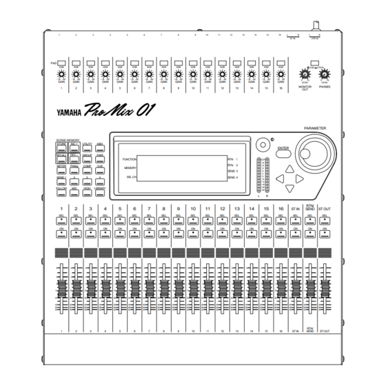
Page 10: Top Panel
Chapter 1: Touring ProMix 01 Top Panel ST IN 2TR IN 20dB 20dB 20dB 20dB 20dB 20dB 20dB 20dB 20dB 20dB 20dB 20dB 20dB 20dB 20dB 20dB CUE/ 2TR IN –16 –60 –16 –60 –16 –60 –16 –60 –16 –60 –16 –60 –16 –60 –16 –60... - Page 11 Top Panel 1. PAD switches These switch the input Pad, which attenuates the input signal by 20 dB. See “Pad” on page 18 for more details. 2. GAIN controls These control the gain of the input preamp. See “Gain” on page 18 for more details.
- Page 12 Chapter 1: Touring ProMix 01 10.PHONES LEVEL control This is used to adjust the headphone output level. 11.MONITOR OUT LEVEL control This is used to adjust the monitor output level. 12.LCD Contrast control This is used to adjust the LCD contrast. Set it so that the LCD appears clear and easy to read.
-
Page 13: Rear Panel
Rear Panel Rear Panel PHANTOM MASTER CH1~8 –10dB +4dB (+48V) (UNBAL) (UNBAL) 2TR IN ST IN INPUT (BAL) ANALOG DIGITAL POWER +4dB +4dB –10dB (UNBAL) (UNBAL) COAXIAL (UNBAL) +4dB (BAL) PHONES MONITOR OUT AUX SEND STEREO OUT REC OUT MIDI 1. - Page 14 Chapter 1: Touring ProMix 01 4. INPUT (BAL) Input channels 1 through 8 have balanced XLR-3-31 type connectors for connecting microphones. The nominal input level is –60dB to Ground +4dB. They are wired according to the IEC 268 standard: Pin 1–ground, pin 2–hot (+), and pin 3–cold (–).
- Page 15 Rear Panel 9. STEREO OUT These are balanced XLR-3-32 type connectors with a +4dB nominal output level. They are wired pin 1–ground, pin 2–hot (+), and pin 3–cold (–).They output the main stereo signals and can be connected Ground to power amplifiers in sound reinforcement applications. Cold Note: When the STEREO OUT XLRs are used with unbalanced con- nectors, their maximum output level is reduced by 6dB.
- Page 16 Chapter 1: Touring ProMix 01 ProMix 01 Block Diagram COMP COMP COMP COMP COMP COMP COMP COMP COMP ProMix 01 User’s Guide...
-
Page 17: An Analog Mixer Analogy
ProMix 01 Block Diagram An Analog Mixer Analogy If ProMix 01 had an analog mixer interface, it might look something like this. If you’re familiar with analog mixers, you may find this illustration reassuring, and the cross references will certainly help you locate infor- mation quickly. - Page 18 Chapter 1: Touring ProMix 01 ProMix 01 User’s Guide...
-
Page 19: User Interface
User Interface User Interface In this chapter... About the User Interface ..... . . 12 LCD Display ....... . . 12 Cursor Buttons . -
Page 20: About The User Interface
Chapter 2: User Interface About the User Interface ProMix 01 user interface is straightforward and easy to use. It consists of a large backlit LCD display, four cursor buttons, a detented PARAMETER wheel, ENTER button, and the channel [SEL] buttons. Each of these are explained in detail in the following sections. -
Page 21: Cursor Buttons
Cursor Buttons Cursor Buttons The cursor buttons are used to select parameters and options on the LCD. The selected parameter or option appears highlighted. Highlighted The [ ] and [ ] cursor buttons move the cursor left and right, and √... -
Page 22: Sel Buttons
Chapter 2: User Interface SEL Buttons The [SEL] buttons are used in conjunction with the LCD functions. To perform an action on a channel, first select it using a [SEL] button, then choose a function using the function buttons to the left of the LCD. -
Page 23: Lcd Functions
LCD Functions LCD Functions ProMix 01 functions without dedicated controls are organized into LCD functions. They are selected using the function buttons to the left of the LCD. The name of the selected LCD function appears in the FUNCTION area of the display. The following table lists all LCD functions and explains what they do. - Page 24 Chapter 2: User Interface ProMix 01 User’s Guide...
-
Page 25: Mixer Functions
Mixer Functions Mixer Functions In this chapter... Phantom Power ......18 Pad . -
Page 26: Phantom Power
Chapter 3: Mixer Functions Phantom Power Phantom power provides a +48V DC power source for condenser type microphones. It is applied to XLR input channels 1 through 8. The PHANTOM MASTER switch on the rear panel is used to turn it PHANTOM MASTER ON and OFF. -
Page 27: Metering
Metering Metering 1. Press [METER]. ProMix 01 features comprehensive signal level metering. Input chan- nels, the stereo input channel, RTN1, RTN2, SEND3, and SEND4 are The METER LCD function all metered using the METER LCD function. The stereo output is appears. -
Page 28: Phase
Chapter 3: Mixer Functions Phase 1. Select a channel using the The Phase function reverses the polarity of the hot and cold feeds in [SEL] buttons. a balanced input (i.e. pins 2 and 3). The phase can be set for the input channels and stereo input channel. - Page 29 1. Select a channel using the ProMix 01 EQ is three-band fully parametric, with variable Q, fre- [SEL] buttons. quency, gain, and ON/OFF parameters. Initially the EQ is configured as a conventional three-band EQ, with shelving-type low and high 2. Press [EQ LOW], [MID], or and peaking-type mid.
-
Page 30: Eq Library
Chapter 3: Mixer Functions EQ Library Recalling EQ Programs The EQ library is used to store EQ settings. Settings are stored as EQ programs, and there are 30 preset programs (1–30) and 20 user pro- 1. Select a channel using the grams (31–50) for you to store your own EQ settings. -
Page 31: Eq Presets
EQ Presets EQ Presets Parameter Program # Program Name Description High Reset the EQ (G = 0dB, F and Q = their RESET 80Hz 2.0kHz 10kHz initial values...same as mix scene 00). SHELF 3/2oct SHELF +5dB +3dB Same as loudness function on a hi-fi LOUDNESS amp. - Page 32 Chapter 3: Mixer Functions Parameter Program # Program Name Description High +2dB +1dB +2dB Wooden bass EQ with low range em- WOOD BASS 80Hz 315Hz 2.2kHz phasis. 3oct 3/2oct SHELF +2dB +3dB +4dB Acoustic guitar EQ with high range ACOUSTIC GUITAR 180hz 4.0kHz 7.0kHz...
-
Page 33: Faders
Faders Faders ProMix 01 faders are motorized, which means that they can position themselves automatically. So all faders in a group or stereo pair move automatically when you move any fader in that group or stereo pair. Fader positions are stored in mix scenes, so when a mix scene is recalled the faders move automatically to their new positions. -
Page 34: Pan And Balance
Chapter 3: Mixer Functions Pan and Balance 1. Select a channel using the The PAN LCD function is used to pan and balance signals. Input [SEL] buttons. channels, the stereo input channel, RTN1, and RTN2 can be panned, and the stereo output can be balanced. 2. -
Page 35: Stereo-Pair Pans
Stereo-Pair Pans Stereo-Pair Pans When input channels are paired, their pan controls appear as one dual-concentric control (i.e. one control inside the other), as shown below. Horizontal bars, at the bottom of the display, show the pan positions and values of the selected channel pair. When channels are paired using ST RESET, the odd channel is automatically panned hard-left and the even channel, hard-right. - Page 36 Chapter 3: Mixer Functions ProMix 01 User’s Guide...
-
Page 37: Auxiliaries And Effects
Auxiliaries and Effects Auxiliaries and Effects In this chapter... About Auxiliaries ......30 About Effects . -
Page 38: About Auxiliaries
Chapter 4: Auxiliaries and Effects About Auxiliaries ProMix 01 has four auxiliary sends: SEND1, SEND2, SEND3, and SEND4. And two auxiliary returns: RTN1 and RTN2. Auxiliary sends can be configured pre-fader or post-fader. SEND1 and SEND2 are used to feed the internal effects processors: Effect1 and Effect2. RTN1 and RTN2 are used to return the processed signals. -
Page 39: Stereo Input Channel And Sends
Stereo Input Channel and Sends Stereo Input Channel and Sends Input channels 1 through 16 handle only a single signal. The stereo input channel, however, handles two signals: left and right. So before feeding the stereo input signal to the SEND1, SEND2, SEND3, and SEND4 send level controls, the left and right signals are summed to form a mono L+R mix. -
Page 40: Sending A Channel Signal
Chapter 4: Auxiliaries and Effects Sending a Channel Signal 1. Press [SEND1] or [SEND2]. Sending a channel signal via SEND1 or SEND2 is the first step to using effects. There are no master send level controls, so you only need to The SEND1 or SEND2 LCD set the channel send levels. -
Page 41: Returning The Processed Signal
Returning the Processed Signal Returning the Processed Signal Returning the processed signal via RTN1 or RTN2 is the second step to using effects. As explained in the “Sending a Channel Signal” pro- cedure on page 32, the processed signal can be returned into the mix just by raising the RTN/SEND fader. -
Page 42: Recalling Effects Programs
Chapter 4: Auxiliaries and Effects Recalling Effects Programs 1. Press [SEND1] or [SEND2]. There are 30 preset effects programs (1–30) and 10 user effects pro- grams (31–40). The SEND1 or SEND2 LCD function appears. If you didn’t Shown below is the SEND1 LCD function. The SEND2 LCD function exit after your last effect edit, is essentially the same. -
Page 43: Editing Effects Programs
Editing Effects Programs Editing Effects Programs 1. Press [SEND1] or [SEND2]. You can edit all effects programs, however, you can store only to user effects locations. So if you edit a preset program, you must store it as The SEND1 or SEND2 LCD a user program. -
Page 44: Storing Effects Programs
Chapter 4: Auxiliaries and Effects Storing Effects Programs 1. Press [SEND1] or [SEND2]. There are 10 user effects programs (31–40) for you to store your own effects settings. When STORE is selected on the SEND LCD function, The SEND1 or SEND2 LCD user program 31, the first user location, is selected automatically. -
Page 45: Preset Effects Program Parameters
Preset Effects Program Parameters Preset Effects Program Parameters Program 1—REVERB HALL 1 Simulates the reverb of a large concert hall. Parameter Setting Range Description Rev.time 2.8s 0.3–30.0s Reverb time. High Ratio 0.1–1.0 High frequency decay ratio. Diffusion 0–10 Reverb diffusion. Ini.Dly 40.0ms 0.1–200.0ms... - Page 46 Chapter 4: Auxiliaries and Effects Program 5—REVERB STAGE Similar to REVERB HALL, but brighter. You can create a live atmosphere by applying a little of this effect to the mix. Parameter Setting Range Description Rev.time 3.4s High Ratio Diffusion Same as program 1 Same as program 1 Ini.Dly 45.0ms...
- Page 47 Preset Effects Program Parameters Program 9—REV LIVE ROOM 1 Simulates the reverb of a live room. Reverb reflections are stronger than those of REVERB ROOM. Parameter Setting Range Description Rev.time 2.4s High Ratio Diffusion Same as program 1 Same as program 1 Ini.Dly 0.1ms 7.0kHz...
- Page 48 Chapter 4: Auxiliaries and Effects Program 13—FLANGE->REVERB Stereo flange followed by reverb. Parameter Setting Range Description Mod.Freq 1.4Hz 0.1–20.0Hz Flange modulation speed. Mod.Depth 0–100% Flange modulation depth. The amount of modulation. FB.Gain +45% –99...+99% Feedback gain. The amount of processed signal fed back into the flanger. Mod.Dly 13.0ms 0.0–15.5ms...
- Page 49 Preset Effects Program Parameters Program 16—CHORUS->DLY LCR Stereo chorus followed by a three-part (L-C-R) delay with feedback. Parameter Setting Range Description Mod.Freq 0.8Hz 0.1–20.0Hz Chorus modulation speed. Mod.Depth 0–100% Chorus modulation depth. The amount of modulation. Mod.Dly 5.9ms 0.0–24.0ms Chorus modulation delay. The delay time before modulation starts. Dly(L) 26.4ms 0.1–618.0ms...
- Page 50 Chapter 4: Auxiliaries and Effects Program 20—ST.PITCH CHANGE Two-part stereo pitch shifter. Each part has independent pan parameter for stereo effects. Parameter Setting Range Description Pitch –12...+12 Coarse pitch setting for pitch changers 1 and 2. Fine(1) –50...+50 Fine pitch for pitch changer 1. Fine(2) –10 –50...+50...
- Page 51 Preset Effects Program Parameters Program 23—CHORUS A stereo chorus. Produces a rich thickening effect. Good with guitar, bass, and strings. Parameter Setting Range Description Mod.Freq 0.6Hz 0.1–20.0Hz Modulation speed. AM Depth 0–100% Amplitude modulation depth. The amount of amplitude modulation. PM Depth 0–100% Pitch modulation depth.
- Page 52 Chapter 4: Auxiliaries and Effects Program 28—PHASING Stereo phaser. Similar to flange, but different. Good with guitar, strings, and other rich harmonic sounds. Parameter Setting Range Description Mod.Freq 0.5Hz 0.1–20.0Hz Modulation speed. Mod.Depth 0–100% Modulation depth. The amount of modulation. FB.Gain +47% –99...+99%...
-
Page 53: Send3 And Send4
SEND3 and SEND4 SEND3 and SEND4 1. Press [SEND3] or [SEND4]. SEND3 and SEND4 can be used to feed external effects processors, foldback amplifiers, or multitrack recording equipment. When used The SEND3 or SEND4 LCD to feed an external effects processor, the processed signal can be function appears. -
Page 54: Send3-4 Stereo Pair
Chapter 4: Auxiliaries and Effects SEND3-4 Stereo Pair 1. Press [UTILITY]. SEND3 and SEND4 can be linked for use as a stereo pair. In this way they can, essentially, be used as another pair of stereo outputs, allow- The UTILITY menu appears. ing for another stereo mix to be set up. -
Page 55: Send3-4 Channel Pans & Balance
SEND3-4 Channel Pans & Balance SEND3-4 Channel Pans & Balance In SEND3-4 Stereo mode, a SEND3-4 pan control is available on each input channel and a SEND3-4 balance control is available on the ste- reo input channel (ST IN). These controls appear on the SEND3-4 LCD function, shown below. -
Page 56: Send3-4 Block Diagram
Chapter 4: Auxiliaries and Effects SEND3-4 Block Diagram This block diagram shows what happens when SEND3 and SEND4 are configured as a stereo pair: Input channel SEND3 and SEND4 controls become a single control, and a SEND3-4 pan control appears. On the stereo input channel, a SEND3-4 balance control appears. -
Page 57: Cue
In this chapter... About CUE ........50 CUE Modes . -
Page 58: About Cue
Chapter 5: CUE About CUE ProMix 01 CUE provides comprehensive monitoring of virtually all inputs and outputs. The CUE signal is output to the MONITOR OUTPUT and PHONES. Output levels are controlled using the MONITOR OUT LEVEL control and PHONES LEVEL control, respectively. -
Page 59: Setting The Cue Mode
Setting the CUE Mode Setting the CUE Mode 1. Press [CUE]. CUE modes are set on the CUE LCD function, shown below. The name of the current CUE mode is highlighted. The PARAMETER The CUE LCD function wheel is used to select modes. When another mode is selected, its appears. -
Page 60: Cue Lcd Function Info
Chapter 5: CUE CUE LCD Function Info As well as being used to set the CUE mode, the CUE LCD function displays various information about the currently selected channel. The exact information shown depends on the type of channel selected. CUE displays for each type of channel are shown below. Input Channel This is the CUE LCD function when an input channel is selected. -
Page 61: Stereo Input Channel
CUE LCD Function Info Stereo Input Channel This is the CUE LCD function for the stereo input channel. Group Phase Dual Pan CUE mode ST IN ON/OFF SEND PRE/POST ST IN selected EQ curve EQ ON/OFF ST IN meters ST IN: ST IN-to-mix fader S1: ST IN-to-SEND1 fader S2: ST IN-to-SEND2 fader S3: ST IN-to-SEND3 fader... - Page 62 Chapter 5: CUE RTN1, RTN2 This is the CUE LCD function for RTN1 and RTN2. RTN balance CUE mode RTN ON/OFF Selected RTN RTN-to-mix fader EQ ON/OFF EQ curve RTN meter Stereo Output This is the CUE LCD function for the stereo output. COMP patch ST OUT balance CUE mode...
-
Page 63: Groups And Pairs
Groups and Pairs Groups and Pairs In this chapter... Grouping Faders ......56 Listening to Groups . -
Page 64: Grouping Faders
Chapter 6: Groups and Pairs Grouping Faders 1. Press [GROUP]. Faders can be grouped for multiple fader control using one fader. This makes it easy to control several faders simultaneously. The input The GROUP LCD function channel and stereo input channel faders can be used in groups. There appears. -
Page 65: Group Block Diagram
Group Block Diagram Group Block Diagram This block diagram shows what happens when channels are grouped. Faders are linked for simultaneous control and the group CUE func- tion is active. See “Listening to Groups” on page 56 for details about group CUE. -
Page 66: Pairing Channels
Chapter 6: Groups and Pairs Pairing Channels 1. Press [PAIR]. Adjacent input channels can be paired for stereo operation. This makes it easy to work with stereo input signals, because you only have The PAIR LCD function to adjust one channel to control both left and right signals. Up to eight appears. -
Page 67: Pair Block Diagram
Pair Block Diagram Pair Block Diagram This block diagram shows what happens when adjacent input chan- nels are paired: PHASE, EQ, COMP patch, faders, ON/OFF, CUE, SEND1, SEND2, SEND3, and SEND4 are linked for simultaneous control. The dotted lines show which channel functions are linked. The send PRE/POST switches are always linked. - Page 68 Chapter 6: Groups and Pairs ProMix 01 User’s Guide...
-
Page 69: Scene Memories
Scene Memories Scene Memories In this chapter... What are Scene Memories? ..... 62 What’s Stored in a Scene Memory? ....62 What is the Edit Buffer? . -
Page 70: What Are Scene Memories
Chapter 7: Scene Memories What are Scene Memories? Scene memories are memory locations used to store mix scenes. A mix scene consists of all ProMix 01 mix settings. Up to 50 mix scenes can be stored and each can be named for easy identification. They can be stored and recalled manually using the [STORE] and [RECALL] buttons. -
Page 71: Storing Mix Scenes
Storing Mix Scenes Storing Mix Scenes 1. Press [STORE]. There are 50 scene memories, so you can store up to 50 mix scenes. More can be saved to a MIDI data filer. See “Bulk Dump/Request” on The MEMORY STORE LCD page 85. -
Page 72: Recalling Mix Scenes
Chapter 7: Scene Memories Recalling Mix Scenes 1. Press [RECALL]. Mix scenes are recalled using the [RECALL] button. They can also be recalled using MIDI Program Changes. See “Program Change” on The MEMORY RECALL LCD page 82. function appears. You can also go to the MEMORY LCD Shown below is the MEMORY RECALL LCD function that appears function by pressing the... -
Page 73: Protecting Scene Memories
Protecting Scene Memories Protecting Scene Memories 1. Press [UTILITY]. You can protect stored mix scenes against accidental overwriting using this Memory Protect function. This is useful when you’ve set The UTILITY menu appears. up many mix scenes for repeated use, or when non-experienced users 2. - Page 74 Chapter 7: Scene Memories ProMix 01 User’s Guide...
-
Page 75: Dynamics Processors
Dynamics Processors Dynamics Processors In this chapter... ProMix 01 Dynamics Processors ....68 Preset Dynamics Programs ..... 68 Processor Types . -
Page 76: Promix 01 Dynamics Processors
Chapter 8: Dynamics Processors ProMix 01 Dynamics Processors ProMix 01 features three stereo dynamics processors, for compres- sion, limiting, gating, and ducking. They can be patched into input channels, SEND3, SEND4, and the stereo outputs. Processor settings are organized as programs, and there are 10 preset programs (1–10) and 10 user programs (11–20) for you to store your own settings. - Page 77 Processor Types Compressor parameters are: Threshold (–40...+18dB) — This determines the level of input sig- nal required to trigger the compressor. Signals at a level below the threshold pass through unaffected. Signals at and above the threshold Compression ratio = 2:1 level are compressed by the amount specified using the Ratio param- eter.
- Page 78 Chapter 8: Dynamics Processors Gate A gate, or noise gate is essentially an audio switch used to mute signals below a set threshold level. It can be used to cut background noise picked up by open microphones, noise and hiss from guitar valve amps and effects pedals, and leakage between drum microphones.
- Page 79 Processor Types Ducking Ducking is commonly used for voice-over applications, where the background music level is reduced automatically when an announcer speaks. Ducking is achieved by triggering a compressor with a differ- ent sound source. For example, a ducker is patched into the back- ground music channel, and the KEY IN signal is sourced from the announcer’s microphone channel.
-
Page 80: Patching In A Processor
Chapter 8: Dynamics Processors Patching in a Processor 1. Press [COMP] repeatedly to Dynamics processors can be patched into the input channels, SEND3, select a processor: 1, 2, or 3. SEND4, and stereo output. The SEND3, SEND4, and stereo outputs patches can configured to pre-fader or post-fader. -
Page 81: Dynamics Processor Meters
Dynamics Processor Meters KEY IN — this is used to select the processor trigger source. (i.e. the signal that triggers, or activates the processor). The current setting is highlighted. Other settings flash when selected. Settings are activated by pressing [ENTER]. The options are: KEY IN Source... -
Page 82: Pre-Fader Or Post-Fader Patches
Chapter 8: Dynamics Processors Pre-Fader or Post-Fader Patches 1. Press [UTILITY]. SEND3, SEND4, and stereo output dynamics processor patch points can be configured pre-fader or post-fader. These settings are made on The UTILITY menu appears. the OUTPUT COMP PATCH POINT LCD function, shown below. 2. -
Page 83: Recalling A Dynamics Program
Recalling a Dynamics Program Recalling a Dynamics Program 1. Press [COMP] repeatedly to There are 10 preset programs (1–10) and 10 user programs (11–20). select a processor: 1, 2, or 3. Shown below is the COMP LCD function. Setup parameters appear The COMP LCD function in the top part of the display. -
Page 84: Editing A Dynamics Program
Chapter 8: Dynamics Processors Editing a Dynamics Program 1. Press [COMP] repeatedly to You can edit all dynamics programs, however, you can store only to select a processor: 1, 2, or 3. user locations. So if you edit a preset program, you must store it as a user program. -
Page 85: Storing A Dynamics Program
Storing a Dynamics Program Storing a Dynamics Program 1. Press [COMP] repeatedly to There are 10 user dynamics programs (11–20) for you to store your select a processor: 1, 2, or 3. own settings. When STORE is selected on the COMP LCD function, user program 11, the first user program, is selected automatically. -
Page 86: Preset Dynamics Processor Parameters
Chapter 8: Dynamics Processors Preset Dynamics Processor Parameters Type Program # Program Name Description Parameters Threshold Ratio Attack Release Out Gain –40...+18dB 1:1– :1 0–120ms 0.1–6.0s –18...+18dB Typical mix compression for TOTAL COMP 50ms 3.0s +1dB adding punch and definition. RADIO COMP Typical FM radio compression. -
Page 87: Midi
MIDI MIDI In this chapter... MIDI and ProMix 01 ......80 MIDI Setup ........81 Program Change . -
Page 88: Midi And Promix 01
Chapter 9: MIDI MIDI and ProMix 01 The true power of ProMix 01 can be realized with MIDI. Used in con- junction with a controlling computer or MIDI sequencer, mix scenes can be recalled automatically, providing snapshot mix automation. In addition, all mix parameters can be controlled in real time, providing dynamic mix automation. -
Page 89: Midi Setup
MIDI Setup MIDI Setup 1. Press [MIDI]. The MIDI SETUP LCD function shown below is used to set basic MIDI parameters. The MIDI menu appears. 2. Select MIDI SETUP and press [ENTER]. The MIDI SETUP LCD function appears. 3. Use the cursor buttons to select parameters and the PARAMETER wheel to set The parameters are:... -
Page 90: Program Change
Chapter 9: MIDI Program Change 1. Press [MIDI]. MIDI Program Change messages are used to recall ProMix 01 mix scenes, providing snapshot mix automation. When a mix scene is The MIDI menu appears. recalled using the [RECALL] button, a Program Change message is 2. -
Page 91: Control Change
Control Change Control Change 1. Press [MIDI]. In conjunction with a controlling computer or MIDI sequencer, MIDI Control Change messages are used to control ProMix 01 mix The MIDI menu appears. parameters in real time, providing dynamic mix automation. When 2. - Page 92 Chapter 9: MIDI Register — all Control Changes use the Tx Ch MIDI Channel, and Control Change #98 (Non-Registered Parameter LSB) is used to spec- ify banks. To reset the Control Change assignments to their initial values, select RESET and press [ENTER]. An “Are your sure” message appears. Select YES to reset, NO to cancel, then press [ENTER] again.
-
Page 93: Bulk Dump/Request
Bulk Dump/Request Bulk Dump/Request 1. Press [MIDI]. The BULK DUMP/REQUEST LCD function has two operating modes: Bulk Dump and Bulk Request. Bulk Dump outputs the The MIDI menu appears. selected data as MIDI Bulk Dump data. This is used to store 2. -
Page 94: Local On/Off
Chapter 9: MIDI Local ON/OFF 1. Press [MIDI]. The LOCAL ON/OFF LCD function allows you to use the ProMix 01 faders and CH1–16 [SEL] buttons to control another ProMix 01, or The MIDI menu appears. a MIDI device that responds to MIDI Control Change and Program 2. -
Page 95: Memory Control Change Out
Memory Control Change Out Memory Control Change Out 1. Press [MIDI]. The MEMORY CONTROL CHANGE OUT LCD function allows you to selectively output mix scene data as MIDI Control Change mes- The MIDI menu appears. sages. This can be used to selectively update mix scene data on another 2. - Page 96 Chapter 9: MIDI ProMix 01 User’s Guide...
-
Page 97: Other Functions
Other Functions Other Functions In this chapter... Using the Oscillator ......90 Checking the Battery ......91 ProMix 01 Initialization . -
Page 98: Using The Oscillator
Chapter 10: Other Functions Using the Oscillator 1. Press [UTILITY]. ProMix 01 features a useful sine wave oscillator that can be assigned to SEND3, SEND4, and the stereo output. Since it’s digital, it is highly The UTILITY menu appears. accurate and produces a very clean sine wave. It can also produce pink 2. -
Page 99: Checking The Battery
Checking the Battery Checking the Battery 1. Press [UTILITY]. ProMix 01 uses a long-life battery to backup its RAM memory. The battery should last for up to five years, and you can check its condition The UTILITY menu appears. using the BATTERY CHECK function. 2. -
Page 100: Promix 01 Initialization
Chapter 10: Other Functions ProMix 01 Initialization 1. Power OFF ProMix 01. This function allows you to reset all ProMix 01 mix settings, mix scenes, user effects programs, user EQ programs, and user dynamics 2. Press and hold down programs to their initial settings (i.e. their factory settings). [STORE] and [INC+]. -
Page 101: Troubleshooting
Troubleshooting Troubleshooting Trouble Remedy Make sure that the ProMix 01 power cable is connected to an AC receptacle of the type marked on the rear panel. ProMix 01 cannot be powered ON. Make sure that the POWER switch is in the ON position. If installed, check the mains plug fuse. - Page 102 Troubleshooting ProMix 01 User’s Guide...
-
Page 103: Appendix
Appendix Appendix In this chapter... LCD Function Map ......96 Button Protector ......97 Data Types . -
Page 104: Lcd Function Map
Appendix LCD Function Map UTILITY menu OSCILLATOR P.90 SEND3, 4 CONFIGURATION P.49 OUTPUT COMP PATCH POINT P.74 MEMORY PROTECT P.65 BATTERY CHECK P.91 MIDI menu MIDI SETUP P.81 PROGRAM CHANGE ASSIGN P.82 CONTROL CHANGE ASSIGN P.83 BULK DUMP/REQUEST P.85 LOCAL ON/OFF P.86 MEMORY CONTROL CHANGE OUT P.87... -
Page 105: Button Protector
Button Protector Button Protector If you find that your hand accidentally presses the ST OUT [ON] but- ton when operating the PARAMETER wheel, affix the self-adhesive Button Protector as shown below. PARAMETER ENTER CLIP –6 –12 –18 –24 –40 RTN/ ST IN SEND ST OUT... -
Page 106: Data Types
Appendix Data Types Mix Scene Data Data Source Details Mix scene name Eight characters CH1–16, ST IN, SEND3, SEND4, ON/OFF buttons ON/OFF RTN1, RTN2, ST OUT Phase settings CH1–16, ST IN Normal/reverse CH1–16, ST IN, RTN1, RTN2, ST ON/OFF, frequency, gain, Q/shelf CH1–16, ST IN, RTN1, RTN2. - Page 107 Data Types Setup Memory Data MIDI Data Details Tx channel 1–16 Rx channel 1–16 Control Change mode Channel/register Control Change Tx ON/OFF Control Change Rx ON/OFF Control Change OMNI ON/OFF Control Change ECHO ON/OFF Program Change Tx ON/OFF Program Change Rx ON/OFF Program Change OMNI ON/OFF...
-
Page 108: Error Messages
Appendix Error Messages ERROR! System Error[1] A fatal error has occurred. Initialize ProMix 01. See “ProMix 01 Ini- tialization” on page 92. ERROR! System Error[2] A fatal error has occurred. Initialize ProMix 01. See “ProMix 01 Ini- tialization” on page 92. ERROR! System Error[3] A fatal error has occurred. - Page 109 Error Messages MIDI Parity Error A MIDI receive error has occurred. Check the transmission data and connecting cable. MIDI Framing Error A MIDI receive error has occurred. Check the transmission data and connecting cable. MIDI Over Run Error A MIDI receive error has occurred. Reduce the transmission data. SUB->MAIN CPU Parity Error An error has occurred while receiving fader data from the CPU.
- Page 110 Appendix MAIN->SUB Over Run Error An error has occurred while receiving fader data from the CPU. WARNING! No battery. No battery is installed. Ask your Yamaha dealer to install one. WARNING! Low battery. Battery power is getting low. Ask your Yamaha dealer to install a new battery.
- Page 111 Error Messages BULK Transmit(TX) OFF! Set BULK TX to ON on the MIDI SETUP LCD function, then try again. Control Change Transmit(TX) OFF! Set CONTROL TX to ON on the MIDI SETUP LCD function, then try again. Parameter not assigned. A parameter not assigned to a Control Change was found when trying to transmit mix scene data.
-
Page 112: Promix 01 Compatible Products
Appendix ProMix 01 Compatible Products MFC1 MIDI Foot Controller The MFC1 is a MIDI foot controller that can transmit MIDI Program Change messages. This could be used with ProMix 01 for recalling mix scenes. With the addition of an optional FC7 Foot Controller and footswitch, the MFC1 can also transmit MIDI Control Change mes- sages, which could be used for real-time ProMix 01 parameter control. -
Page 113: General Specifications
General Specifications General Specifications Frequency Response 20 Hz–20 kHz +1, –3 dB (@ +4 dB into 600 ) Less than 0.1% (20 Hz–20 kHz @ +14 dB into 600 ) Dynamic Range 105dB typ. (ST IN to ST OUT AD/DA converters) –128dB Equivalent Input Noise Hum &... -
Page 114: Input Specifications
Appendix Input Specifications Input level Actual load For use with Input connection PAD *4 GAIN Mixer connector Sensitivity Max. impedance nominal Nominal before clip –72dB –60dB –40dB –60 (194 V) (775 V) (7.75mV) 50–600 CH INPUT –28dB –16dB +4dB mics & XLR-3-31 type *2 CH1–CH8 (30.9mV) -
Page 115: Digital Out & Midi Specifications
Digital OUT & MIDI Specifications Digital OUT & MIDI Specifications Output connection Format Level Mixer connector DIGITAL OUT (COAXIAL) S/PDIF 0.5Vpk-pk/75 RCA/phono MIDI IN MIDI — 5-pin DIN MIDI OUT MIDI — 5-pin DIN Digital Out Channel Status Format Consumer Category AD converter Copy Prohibit... - Page 116 Appendix ProMix 01 User’s Guide...
-
Page 117: Glossary
Glossary Glossary A/D converter — An electronic device that converts analog signals into digital signals. Aliasing — A type of signal distortion that occurs during A/D con- version if the sampling frequency is less than twice that of the highest audio frequency. - Page 118 Glossary Dynamic mix automation — Mixdown automation where mix settings are adjusted in real time. Dynamic range — The difference between the loudest and quietest signal levels in a system. In an audio device, usually the difference between the maximum output level and the residual noise floor. In a digital system, the available dynamic range is determined by the data resolution, about 6dB per digital bit.
- Page 119 Glossary Peaking — A type of EQ circuit used to cut and boost a band of fre- quencies. It produces a mountain-peak type response curve. The width of the frequency band is controlled by the Q parameter. Mid- band EQ is usually of the peaking type. Compare with Shelving. PCM —...
- Page 120 Glossary Shelving — A type of EQ circuit used to cut and boost frequencies above or below a set frequency. It produces a shelf-looking response curve. High and low EQs are usually of the shelving type. ProMix 01 high and lows, however, can also be configured as peaking types. Compare with Peaking.
-
Page 121: Index
Index CHORUS->REVERB 39 preset program parameters 78 CLIP, metering 19 preset programs 68 Coaxial, see Digital out recalling programs 75 COMP FAST 78 storing 77 Numerics COMP HEAVY1 78 with mix scenes 75 COMP HEAVY2 78 COMP SLOW 78 2TR IN COMP, LCD function 72 connection 5 COMP, see Dynamics processors... - Page 122 using 56 LIBRARY, LCD function 22 Nyquist theorem 110 Limiter 69 Local on/off 86 LOCAL ON/OFF, LCD function 86 Low EQ 21 High EQ 21 Octave, Q values 21 Hold OMNI on/off 81 ducker 71 ON buttons 25 gate 70 Oscillator 90 Map, LCD functions 96 OSCILLATOR, LCD function 90...
- Page 123 effects program parameters 37 dual pan 26 Stereo width 27 effects programs 30 returning effects signals 33 Storing EQ programs 23 dynamics processors 77 Program Change effects programs 36 assigning 82 mix scenes 63 on/off 81 SUPER FLANGE 43 S/N ratio 112 PROGRAM CHANGE ASSIGN, LCD SYMPHONIC 43 S/PDIF, see Digital out...
- Page 124 Add-1 Additions ProMix 01 Level Diagram ProMix 01 User’s Guide...
- Page 125 Add-2 ProMix 01 Dimensions W: 435 ProMix 01 User’s Guide...
- Page 126 Add-3 Optional Rack-Mount Ears Optional Wooden Side Panels Use only the screws supplied Utilisez uniquement les vis fournies. Verwenden Sie ausschließlich die beiliegenden Schrauben. Use solamente los tornillos proporcionados. ProMix 01 User’s Guide...
- Page 127 Add-4 Mix Scene to Program Change Assignment Table Program Initial Mix User Mix Program Initial Mix User Mix Program Initial Mix User Mix Change # Scene # Scene # Change # Scene # Scene # Change # Scene # Scene # —...
- Page 128 Add-5 Control Change to Parameter Assignment Table Initial Setup User Setup Data Param # ProMix 01 Parameter Control Control Value Bank Bank Change # Change # Channel Input 1 Level Channel Input 2 Level Channel Input 3 Level Channel Input 4 Level Channel Input 5 Level Channel Input 6 Level Channel Input 7 Level...
- Page 129 Add-6 Initial Setup User Setup Data Param # ProMix 01 Parameter Control Control Value Bank Bank Change # Change # Channel Input 4 Panpot Channel Input 5 Panpot Channel Input 6 Panpot Channel Input 7 Panpot Channel Input 8 Panpot Channel Input 9 Panpot Channel Input 10 Panpot Channel Input 11 Panpot...
- Page 130 Add-7 Initial Setup User Setup Data Param # ProMix 01 Parameter Control Control Value Bank Bank Change # Change # Channel Input 12 to Effect Send 2 Level Channel Input 13 to Effect Send 2 Level Channel Input 14 to Effect Send 2 Level Channel Input 15 to Effect Send 2 Level Channel Input 16 to Effect Send 2 Level Stereo Input to Effect Send 2 Level...
- Page 131 Add-8 Initial Setup User Setup Data Param # ProMix 01 Parameter Control Control Value Bank Bank Change # Change # Channel Input 5 to Send3/4 Panpot(Configuration=Stereo) Channel Input 6 to Send3/4 Panpot(Configuration=Stereo) Channel Input 7 to Send3/4 Panpot(Configuration=Stereo) Channel Input 8 to Send3/4 Panpot(Configuration=Stereo) Channel Input 9 to Send3/4 Panpot(Configuration=Stereo) Channel Input 10 to Send3/4 Panpot(Configuration=Stereo) Channel Input 11 to Send3/4 Panpot(Configuration=Stereo)
- Page 132 Add-9 Initial Setup User Setup Data Param # ProMix 01 Parameter Control Control Value Bank Bank Change # Change # Channel Input 14 Phase Channel Input 15 Phase Channel Input 16 Phase Stereo Input Phase Channel Input 1 Equalizer On/Off Channel Input 2 Equalizer On/Off Channel Input 3 Equalizer On/Off Channel Input 4 Equalizer On/Off...
- Page 133 Add-10 Initial Setup User Setup Data Param # ProMix 01 Parameter Control Control Value Bank Bank Change # Change # Channel Input 5 Low Equalizer Gain Channel Input 6 Low Equalizer Gain Channel Input 7 Low Equalizer Gain Channel Input 8 Low Equalizer Gain Channel Input 9 Low Equalizer Gain Channel Input 10 Low Equalizer Gain Channel Input 11 Low Equalizer Gain...
- Page 134 Add-11 Initial Setup User Setup Data Param # ProMix 01 Parameter Control Control Value Bank Bank Change # Change # Channel Input 13 Mid Equalizer Frequency Channel Input 14 Mid Equalizer Frequency Channel Input 15 Mid Equalizer Frequency Channel Input 16 Mid Equalizer Frequency Stereo Input Mid Equalizer Frequency Effect Return 1 Mid Equalizer Frequency Effect Return 2 Mid Equalizer Frequency...
- Page 135 Add-12 Initial Setup User Setup Data Param # ProMix 01 Parameter Control Control Value Bank Bank Change # Change # Channel Input 2 High Equalizer Frequency Channel Input 3 High Equalizer Frequency Channel Input 4 High Equalizer Frequency Channel Input 5 High Equalizer Frequency Channel Input 6 High Equalizer Frequency Channel Input 7 High Equalizer Frequency Channel Input 8 High Equalizer Frequency...
- Page 136 Add-13 Initial Setup User Setup Data Param # ProMix 01 Parameter Control Control Value Bank Bank Change # Change # Channel Input 9 High Equalizer Q/Shelf Channel Input 10 High Equalizer Q/Shelf Channel Input 11 High Equalizer Q/Shelf Channel Input 12 High Equalizer Q/Shelf Channel Input 13 High Equalizer Q/Shelf Channel Input 14 High Equalizer Q/Shelf Channel Input 15 High Equalizer Q/Shelf...
- Page 137 Add-14 Initial Setup User Setup Data Param # ProMix 01 Parameter Control Control Value Bank Bank Change # Change # Internal Effect 2 Parameter 4 Low Byte Internal Effect 2 Parameter 5 High Byte Internal Effect 2 Parameter 5 Low Byte Internal Effect 2 Parameter 6 High Byte Internal Effect 2 Parameter 6 Low Byte Internal Effect 2 Parameter 7 High Byte...
- Page 138 Add-15 Initial Setup User Setup Data Param # ProMix 01 Parameter Control Control Value Bank Bank Change # Change # Oscillator SEND3 Assign Oscillator SEND4 Assign Oscillator ST OUT Assign Cue mode MIX/LAST CUE/GROUP CUE/STEREO OUT FIX Channel Input 1 Group No. (0: OFF, 1–4: A–D) Channel Input 2 Group No.
-
Page 139: Midi Data Format
Add-16 MIDI Data Format 1 General Items 1-1 This section describes the ProMix 01 MIDI specifications. 1-2 Electrical characteristics and signal specifications conform to the MIDI Standard 1.0. 2 Transmission/Reception ProMix 01 transmits and receives Program Change, Control Change, and System Exclusive messages. Real-time messages, Active Sensing, and MIDI Reset are received only. - Page 140 Add-17 To derive the midway value of the internal data, the following calculation is used (MIDI midway value = 64). First, 128 (the maximum value used in MIDI) is divided by the internal Data Value (Panpot = 33) to obtain the MIDI data number equivalent to one internal data number.
- Page 141 Add-18 3 Transmission Condition CONTROL TX CONTROL CHANGE $BnH PROGRAM TX PROGRAM CHANGE $CnH MIDI TX SYSTEM EXCLUSIVE BULK TX BULK DUMP $F0H, $43H MIDI OUT REQUEST $F0H, $43H CONTROL ECHO MIDI IN PROGRAM ECHO 4 Receive Condition CONTROL RX $BnH CONTROL CHANGE PROGRAM RX MIDI IN...
- Page 142 Add-19 5 Bulk Dump Request Format 5-1 One Memory Mixing Program Bulk Dump Data Format STATUS 11110000 System Exclusive Message ID No. 01000011 Manufacturer’s ID No. (YAMAHA) SUB STATUS 0000xxxx n=0-15(Tx/Rx Channel No.) FORMAT No. 01111110 Universal Bulk Dump BYTE COUNT(HIGH) 00000110 826(408x2+10)bytes BYTE COUNT(LOW)
- Page 143 Add-20 5-3 All Control Change Assignment Table Bulk Dump Data Format STATUS 11110000 System Exclusive Message ID No. 01000011 Manufacturer’s ID No. (YAMAHA) SUB STATUS 0000xxxx n=0-15(Tx/Rx Channel No.) FORMAT No. 01111110 Universal Bulk Dump BYTE COUNT(HIGH) 00010010 2314(96x6x2x2+10)bytes BYTE COUNT(LOW) 00001010 01001100 ‘L’...
- Page 144 Add-21 5-5 Backup Memory Bulk Dump Data Format STATUS 11110000 System Exclusive Message ID No. 01000011 Manufacturer’s ID No. (YAMAHA) SUB STATUS 0000xxxx n=0-15(Tx/Rx Channel No.) FORMAT No. 01111110 Universal Bulk Dump BYTE COUNT(HIGH) 00000001 154(72x2+10)bytes BYTE COUNT(LOW) 00011010 01001100 ‘L’...
- Page 145 Add-22 5-7 Compressor User Memory Bulk Dump Data Format STATUS 11110000 System Exclusive Message ID No. 01000011 Manufacturer’s ID No. (YAMAHA) SUB STATUS 0000xxxx n=0-15(Tx/Rx Channel No.) FORMAT No. 01111110 Universal Bulk Dump BYTE COUNT(HIGH) 00000000 54(22x2+10)bytes BYTE COUNT(LOW) 00110110 01001100 ‘L’...
- Page 146 Add-23 5-9 Key Remote Bulk Dump Data Format (Receive only) STATUS 11110000 System Exclusive Message ID No. 01000011 Manufacturer’s ID No. (YAMAHA) SUB STATUS 0000xxxx n=0-15(Rx Channel No.) FORMAT No. 01111110 Universal Bulk Dump BYTE COUNT(HIGH) 00000000 11(1+10)bytes BYTE COUNT(LOW) 00001011 01001100 ‘L’...
- Page 147 Add-24 5-11 One Memory Mixing Program Bulk Request Data Format STATUS 11110000 System Exclusive Message ID No. 01000011 Manufacturer’s ID No. (YAMAHA) SUB STATUS 0010xxxx n=0-15(Tx/Rx Channel No.) FORMAT No. 01111110 Universal Bulk Dump 01001100 ‘L’ 01001101 ‘M’ 00100000 ‘ ‘ 00100000 ‘...
- Page 148 Add-25 5-14 Scene Memory Store Bulk Request Data Format*17 STATUS 11110000 System Exclusive Message ID No. 01000011 Manufacturer’s ID No. (YAMAHA) SUB STATUS 0010xxxx n=0-15(Tx/Rx Channel No.) FORMAT No. 01111110 Universal Bulk Dump 01001100 ‘L’ 01001101 ‘M’ 00100000 ‘ ‘ 00100000 ‘...
- Page 149 Add-26 5-17 Backup Memory Bulk Request Data Format STATUS 11110000 System Exclusive Message ID No. 01000011 Manufacturer’s ID No. (YAMAHA) SUB STATUS 0010xxxx n=0-15(Rx Channel No.) FORMAT No. 01111110 Universal Bulk Dump 01001100 ‘L’ 01001101 ‘M’ 00100000 ‘ ‘ 00100000 ‘...
- Page 150 Add-27 5-20 Equalizer User Library Bulk Request Data Format STATUS 11110000 System Exclusive Message ID No. 01000011 Manufacturer’s ID No. (YAMAHA) SUB STATUS 0010xxxx n=0-15(Rx Channel No.) FORMAT No. 01111110 Universal Bulk Dump 01001100 ‘L’ 01001101 ‘M’ 00100000 ‘ ‘ 00100000 ‘...
- Page 151 Add-28 Button Number Table Button # Button Name Button # Button Name MEMORY STORE # 38 ST OUT SEL MEMORY UP # 39 CH1 ON UTILITY # 40 CH2 ON MIDI # 41 CH3 ON MEMORY RECALL # 42 CH4 ON MEMORY DOWN # 43 CH5 ON...
- Page 152 Add-29 *1 How to calculate data format. For example, Internal Data: Ds,D1,D2,D3,...,Dx,...,De (Dx is 1 byte data). The data ranges between 00h and FFh. DxH = ASCII ((Dx/16) AND 0Fh) (Character code ‘0’ to ‘F’) DxL = ASCII (Dx AND 0Fh) (Character code ‘0’ to ‘F’) *2 Check sum.
- Page 153 YAMAHA [Digital Mixer] Date: 3 June 1994 Model: ProMix 01 MIDI Implementation Chart Version: 1.0 Function... Transmitted Recognized Remarks Basic Default 1 – 16 1 – 16 Memorized Channel Changed 1 – 16 1 – 16 Default OMNI off / OMNI on Mode Messages OMNI on/off...
- Page 154 YAMAHA CORPORATION P.O.Box 1, Hamamatsu, Japan VS17170 IP 95 01 5000 AP Printed in Japan...
Need help?
Do you have a question about the Programmable Mixer 01 and is the answer not in the manual?
Questions and answers
Cómo lo conecto a una laptop para ver la pantalla?
@Roberto Vallejo Bien en un video de YouTube del 2015 que se puede conectar por vida midi e interfaz Bluetooth más un software y se logra ver en un pad y también en un celular.