
Subscribe to Our Youtube Channel
Related Manuals for Gigabyte Poseidon GZ-XA1CA-STB


Summary of Contents for Gigabyte Poseidon GZ-XA1CA-STB
- Page 1 Poseidon GZ-XA1CA-STB GZ-XA1CA-STS User’s Manual 20070301-GZXA1CA-STBSTS rev. 1002...
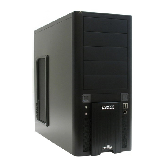
- Page 2 Poseidon Introduction The chassis of Gigabyte Poseidon series is made by high-end Aluminum bezel design with dual 12cm (front and rear) silent fans to offer the best ventilation for the system. The internal cable management and tool-free design provide users with easer installation procedures and computer system management.
-
Page 3: Table Of Contents
Contents Components Introduction ..................... 4 Chassis’s Internal Structure ................4 Side Panel Introduction ..................6 Front and Rear Panel Instruction ..............7 Features ..........................8 Specifi cation .......................... 8 Installation Instruction ......................9 Installation of Power Supply ................9 Installation of Motherboard ................9 Installation of Interface Card ................ -
Page 4: Components Introduction
Components Introduction 1-1 Chassis’s Internal Structure Power supply PCI tool-free fastener Motherboard/panel card 5.25” Front device bay... - Page 5 Build-in hard disk 3.5” Floppy Accessory box a. Standoff x 9 b. Securing runner x 6 c. Motherboard secur- ing screw x 9 e. Power supply f. Magnet ring x 1 d. Wire clamp x 1 securing screw x 4 g.
-
Page 6: Side Panel Introduction
1-2 Side Panel Introduction See-through side panel installation complete fi gure (A-1) (Factory default: vent side panel) 1-2-1 To replace the See-through side panel: Step 1: Release 4 screws at the rear of the side panel to remove the panel. Step 2: Remove the factory default perforated side panel. -
Page 7: Front And Rear Panel Instruction
1-3 Front and Rear Panel Instruction 1-3-1 To remove front panel: Step 1: Remove the left and right side panels ( see Step 1-2-1 on Page 6) and slightly pull out both sides of the upper (see, Figure a) and lower (see Figure b) fasteners (see Figure c). Figure a Figure b Figure c... -
Page 8: Features
Dual 12cm silent & shockproof fan Tool-less design & Hassle-Free Assembly (Rear fan w/ LED) Supports water cooling systems Specifi cation Model : GZ-XA1CA-STB/GZ-XA1CA-STS Case Type : Mid-Tower Dimension : 200 x 440 x 495mm (W x H x D) Front bezel Material... -
Page 9: Installation Instruction
Installation Instruction Please follow the reference sections for installation. 4-1 Installation of Power Supply To facilitate the installation, it is recommended to place the Poseidon chassis upright on the table. Required tool: Power supply securing screw x 4. 4-1-1 Please remove the left side panel before placing the power supply into the chassis. -
Page 10: Installation Of Interface Card
4-3 Installation of Interface Card The Poseidon supports tool-free installation of interface cards, e.g. Graphic card and Network Card, etc. Required tool: None 4-3-1 Unlock securing fasteners of the PCI socket; push the fastener downwards fi rst. 4-3-2 And then, push the fastener upwards. 4-3-3 Remove the internally attached dust-proof PCI cover. -
Page 11: Installation Of Front I/O Panel
4-4 Installation of Front I/O Panel Incorrect connector installation may possibly burn out the motherboard and other components. Be sure to observe the instructions on installation in the manual. Any loss arising from nonobservance of the proper operation provided is not covered by the warranty. -
Page 12: Chassis's Internal Structure
4-4-3 Attach the HD Audio connector to the pin located on the motherboard. Defi nition MIC2_L MIC2_R -ACZ_DET Line2_R FSENSE1 FAUDIO_JD No Pin LINE2_L FSENSE2 Defi nition Defi nition MIC Power NO Pin Line Out (L) Line Out (R) (2) Basic chassis power switch control cable kit. Follow the connectors listed below for installation (see the fi... -
Page 13: Installation Of 5.25" Front Device Bay
4-6 Installation of 5.25” Front Device Bay The installation of 5.25” CD-ROM is also intended for installation of general 5.25” front device bay. Required tool: None 4-6-1 Remove the front panel (see Step 1-3-1 on Page 7) and take off the 5.25” internal metallic panel. -
Page 14: Installation Of Built-In Hdd (Hard Disc Drive)
4-7-3 Refer to the installation order illustrated in the left fi gure and secure the 3.5” fl oppy disc drive by controlling the latch. (Reverse steps for disassembly) 4-7-4 Installation completed. 4-8 Installation of Built-in HDD (Hard Disc Drive) The Poseidon built-in HD drive bay can be installed with up to 3 HDDs. The built-in HDD requires securing runners, which are located in the accessory box below. -
Page 15: Diy Front Bracket Of Projector Light
Required tool: transparent projector panel (slides and laser printer or copy machine should be provided by the user) 4-10-1 Please visit Gigabyte website (http:// gwebmanager1:7001/Products/Chassis/Default. aspx) to search the Poseidon series case products by fi... -
Page 16: Foot Stand Instruction
4-10-6 There is a switch for changing the color of projection lamp on the case; the right side is blue and the left side is white. White Blue (Factory default) 4-10-7 Place the completed transparency plate on the bottom position of the front panel and refi t the front panel. -
Page 17: Liquid Cooling System Support
4-12 Liquid Cooling System Support The Poseidon series chassis can fully support the Gigabyte 3D Galaxy Liquid cooling kit (also support most of the liquid cooling systems commercially available). While installing the liquid cooling system, please consult its manual fi rst.
Need help?
Do you have a question about the Poseidon GZ-XA1CA-STB and is the answer not in the manual?
Questions and answers