
Related Manuals for Gigabyte GZ-XX1CA-SNS


Summary of Contents for Gigabyte GZ-XX1CA-SNS
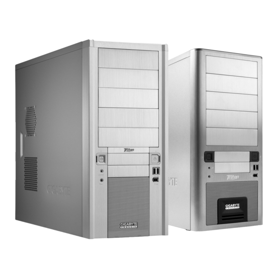
- Page 1 Triton Series Triton + Triton 180 Triton GZ-XX1CA-SNS/SNB Triton 180 GZ-AX1CA-SDS/SDB GZ-AX1CA-SD1/SD2 English User’s Manual...
- Page 2 For further information and specifications of the “Triton” series, please visit GIGABYTE website. (http://www.gigabyte.com.tw) The Following are not covered by the warranty: 1. Using the product incorrectly or in a manner other than the designed purpose.
-
Page 3: Table Of Contents
Table of Contents 1. Components Introduction 1-1 Casing’s Internal Structure 1-2 Front and Rear Panel Structure 5 1-3 Removal of Side and Front Panels 2. Features 6 3. Specifications 7 4. Installation Instructions 4-1 Installation of Power Supply ... -
Page 4: Components Introduction
1.Components Introduction 1-1 Casing’s Internal Structure Power Supply Motherboard PCI Tool-Free Tray Fastener 5.25” Front 3.5” Front 3.5” Internal Device Bay Device Bay Device Bay... -
Page 5: Front And Rear Panel Structure
Securing Runner Copper Stand Off Motherboard Securing Screw x 9 Accessory Box Power Supply Wire Clamp x 1 Magnet Ring x 1 Securing Screw x 4 USB 2.0 Audio Set IEEE1394 (HD & AC’97) (Multi-connectors) Front Cable Kit 3-Pin Fan Basic chassis power Connector switch control cable kit... -
Page 6: Removal Of Side And Front Panels
1-3 Removal of Side and Front Panels 1-3.1 To remove side panels: 1-3.1a Remove the 4 thumb screws at the rear of the side panels, and detach the side panels. 1-3.2 To remove front panel: 1-3.2a Remove the left and right side panels (see step 1-3.1), release ... -
Page 7: Specifications
3.Specifications Triton Triton 180 GZ-AX1CA-SDS/SDB Model GZ-XX1CA-SNS/SNB GZ-AX1CA-SD1/SD2 Case Type Middle Tower Size (W x H x D) 200 x 440x 480 mm Front Bezel Material Aluminum Color Silver / Black Side Panel Intel CAG1.1 Body Material 0.7 mm SECC Net Weight 8.4kg... -
Page 8: Installation Instructions
4.Installation Instructions Please follow the reference sections in order for installation. 4-1 Installation of Power Supply To facilitate the installation, it is recommended to set the chassis upright on the table. Required Tools: Power supply securing screw x 4. 4-1.1 Remove side panel (see step 1-3.1 on page 6). -
Page 9: Installation Of Add-On Card
4-2.3 Secure the motherboard with the motherboard screws (refer to your motherboard manual to check what type of motherboard you have). Motherboard Case copper Motherboard Code name screws post A1-A9 Micro ATX U1-U9 Flex ATX F1-F6 4-3 Installation of Add-on Card This chassis supports tool-free installation of add-on cards, e.g. -
Page 10: Installation Of Front Multi-Media I/O Port
4-4 Installation of Front Multi-Media I/O Ports Incorrect connection of the slots can possibly cause the motherboard to malfunction or completely destroy the motherboard. Please read the installation procedure within the user manual as incorrect installations or connections causing faults will void your warranty. The front panel consists of: (1) 2 x USB, 1 x IEEE 1394 and 1 x Audio Set (HD &... -
Page 11: Installation Of Fan Power Cable
Insert the Audio connector into the corresponding 4-4.3 socket on the motherboard. HD AUDIO Definition Definition MIC2_L FSENSE1 FAUDIO_JD MIC2_R -ACZ_DET LINE2_L LINE2_R FSENSE2 AC'97 Definition Definition MIC Power Line Out(L) Line Out(R) (2) Basic casing power switch control cable kit. Follow the connectors list below for installation (see figure below) Connector... -
Page 12: Installation Of 5.25" Front Device Bay
4-6 Installation of 5.25” Front Device Bay This chassis can accommodate up to 5 x 5.25” front devices. Required Tools: None Detach the front panel (see step 1-3.2 on page 6) and remove 4-6.1 the mesh drive rail from the front panel. 4-6.2 Remove the front EMI plate and attach the front panel onto the chassis. -
Page 13: Installation Of 3.5" Internal Device Bay
proof foot supports for ensuring the casing is firmly seated on the holding surface. 4-10 Liquid Cooling System This chassis can fully support the GIGABYTE 3D Galaxy liquid cooling system (it also supports majority of liquid cooling systems available commercially). While installing the liquid cooling system, please refer to the manual provided with the liquid cooling system. -
Page 14: Recommended Cooling Products
4-11 Recommended Cooling Products This chassis is recommended to be used with GIGABYTE cooling products.
Need help?
Do you have a question about the GZ-XX1CA-SNS and is the answer not in the manual?
Questions and answers