
Related Manuals for Eagle Cuda 240 S/GPS


Summary of Contents for Eagle Cuda 240 S/GPS
- Page 1 Pub. 988-0152-011 www.eaglesonar.com Cuda 240 S/GPS Fish-finding Sonar & GPS Plotter Installation and Operation Instructions...
- Page 2 Eagle Electronics Marine-Tex is a trademark of Illinois Tool Works Inc. Eagle Electronics may find it necessary to change or end our policies, regulations, and special offers at any time. We reserve the right to do so without notice.
-
Page 3: Table Of Contents
Sec. 1: Read Me First! ... 1 Capabilities and Specifications: Cuda 240... 2 How your Sonar Works... 4 How your GPS Works ... 4 Introduction to GPS and WAAS... 5 How to Use this Manual: Typographical Conventions... 7 Sec. 2: Installation & Accessories ... 9 Preparations... - Page 4 FasTrack ... 49 Fish I.D. (Fish Symbols & Depths) ... 50 FishTrack ... 51 Grayline ... 51 Overlay Data ... 52 Ping Speed & HyperScroll... 54 Reset Options ... 55 Sensitivity & Auto Sensitivity... 56 To Turn Auto Sensitivity Back on:... 57 Set Keel Offset ...
- Page 5 Find a Waypoint... 86 Navigate to a Waypoint ... 88 Set Man Overboard (MOB) Waypoint... 89 Navigate Back to MOB Waypoint ... 89 Trails ... 90 Creating and Saving a Trail ... 90 Delete a Trail ... 92 Display a Saved Trail ... 92 Edit a Trail Name ...
- Page 6 Overlay Data ... 113 To Select Data for Display: ... 114 To Turn Off Displayed Data: ... 114 To Change Displayed Data Font Size: ... 115 Pop-Up Help ... 116 Position Pinning... 116 Reset Options ... 117 Screen Contrast and Brightness ... 117 Set Language ...
-
Page 7: Section 1: Read Me First
GPS receiver. First, we want to thank you for buying a Eagle sonar/GPS unit. Whether you're a first time user or a professional fisherman, you'll dis- cover that your unit is easy to use, yet capable of handling demanding navigation and sonar tasks. -
Page 8: Capabilities And Specifications: Cuda 240
If you're having difficulty with your sonar, you can find an answer to the most common problems in Section 5, Sonar Troubleshooting. The manual switches from sonar to navigation in Section 6, which in- troduces you to Basic GPS Operations. This section features a one- page GPS Quick Reference on page 79. - Page 9 Back-up memory: ... Built-in memory stores GPS data for dec- Languages:... 10; menu languages selectable by user. Frequency:... 200 kHz. Transducer:... A Skimmer Transmitter: ... 800 watts peak-to-peak; 100 watts RMS. Sonar sounding depth capability: ... 600 feet (180 meters). Actual capability de- Depth display:...
-
Page 10: How Your Sonar Works
Sonar has been around since the 1940s, so if you already know how it works, skip down to read about the relatively new technology of GPS. But, if you've never owned a sonar fish finder, this segment will tell you the underwater basics. -
Page 11: Introduction To Gps And Waas
& Accessories on page 9. If you're new to GPS, read on, and you can later impress your friends with your new-found knowledge.) First, think of your unit as a small but powerful computer. (But don't worry — we made this unit easy to use, so you don't need to be a com- puter expert to find your way!) The unit includes a keypad and a screen with menus so you can tell it what to do. - Page 12 GPS proved so useful for civilian navigation that the federal govern- ment discontinued SA on May 2, 2000, after the military developed other methods to deny GPS service to enemy forces. Reliable accuracy for civilian users jumped from 100 meters (330 feet) under SA to the present level of 10 to 20 meters (about 30 to 60 feet.) Twenty-four satellites orbit 10,900 nautical miles above the Earth, passing overhead twice daily.
-
Page 13: How To Use This Manual: Typographical Conventions
GPS alone is plenty accurate for route navigation, but the U.S. Federal Aviation Administration has special aircraft navigation needs that go beyond basic GPS. So, the FAA has developed a program to boost GPS performance with its Wide Area Augmentation System, or WAAS. The FAA commissioned the system on July 11, 2003. - Page 14 tal line depth cursor on the sonar screen. The arrow keys help you move around the menus so you can execute different commands. They are represented by symbols like these, which denote the down arrow key, the up arrow, the left arrow and the right arrow: ↓ ↑ ← →. Keyboard The other keys perform a variety of functions.
-
Page 15: Section 2: Installation & Accessories
Installation & Accessories Preparations You can install the sonar and GPS systems in some other order if you prefer, but we recommend this installation sequence: CAUTION: You should read over this entire installation section before drill- ing any holes in your vehicle or vessel! 1. -
Page 16: Recommended Tools And Supplies
Remember, the transducer location and installation is the most critical part of a sonar installation. Recommended Tools and supplies If you prefer the option of routing the cable through the transom, you will need a 5/8" drill bit. NOTE: The following installation types also call for these recommended tools and required supplies that you must provide (supplies listed here are not included): Transom installation... -
Page 17: How Low Should You Go
boat hulls have a flat keel pad that offers a good mounting surface. On vee hulls, try to place the transducer where the deadrise is 10° or less. Left, vee pad hull; right, vee hull. A pod style transducer is shown here, but the principle is the same for Skimmers inside a hull. -
Page 18: Shoot-Thru-Hull Vs. Transom Mounting
Transducer centerline Align transducer centerline with hull bottom. However, there are times when you may need to adjust the transducer slightly higher or lower. (The slots in the mounting brackets allow you to loosen the screws and slide the transducer up or down.) If you fre- quently lose bottom signal lock while running at high speed, the trans- ducer may be coming out of the water as you cross waves or wakes. -
Page 19: Transom Transducer Assembly And Mounting
Second, the transducer angle cannot be adjusted for the best fish arches on your sonar display. (This is not an issue for flasher-style sonars.) Lack of angle adjustment can be particularly troublesome on hulls that sit with the bow high when at rest or at slow trolling speeds. Third, a transducer CAN NOT shoot through wood and metal hulls. - Page 20 Reassemble the transducer and bracket and place them against the transom. Again, check to see if you can move the transducer so it's parallel with the ground. If you can, then go to step 3. If it doesn't, repeat step 2, but use a different alignment letter until you can place the transducer on the transom correctly.
- Page 21 Transom Position transducer mount on transom and mark mounting holes. Side view shown at left and seen from above at right. 5. Attaching transducer to transom. Remove the transducer from the bracket and re-assemble it with the cable passing through the bracket over the bolt as shown in the following figures.
-
Page 22: Trolling Motor Bracket Installation
6. Route the transducer cable through or over the transom to the sonar unit. Make sure to leave some slack in the cable at the transducer. If possible, route the transducer cable away from other wiring on the boat. Electrical noise from the engine's wiring, bilge pumps, VHF radio wires and cables, and aerators can be picked up by the sonar. -
Page 23: Transducer Orientation And Fish Arches
3. Route the transducer cable alongside the trolling motor shaft. Use plastic ties (not included) to attach the transducer cable to the troll- ing motor shaft. Make sure there is enough slack in the cable for the motor to turn freely. Route the cable to the sonar unit and the trans- ducer is ready for use. -
Page 24: Shoot-Thru-Hull Preparation And Installation
If the arch slopes up – but not back down – then the front of the trans- ducer is too high and needs to be lowered. If only the back half of the arch is printed, then the nose of the transducer is angled too far down and needs to be raised. - Page 25 Testing Determines Best Location Ideally, the shoot-thru transducer should be installed as close to the transom as possible, close to the centerline. This will give you the best performance during high speed maneuvers. Transducer location (high speed) Shoot-thru-hull transducer locations for high speed or trolling speed operation.
- Page 26 2. Next, take the transducer out of the water and place it in the water in the sump of the boat, face down. (The transducer face is shown in the figure on the following page.) Notice how the signal strength de- creases.
- Page 27 Sand this surface WARNING: Use only the epoxy available from LEI. It has been for- mulated to work with these installation procedures. Other epoxy types may be too thin or may not cure to the right consistency for optimum transducer performance. 2.
-
Page 28: Power And Cable Connections
5. After the epoxy has cured, route the cable to the sonar unit and it's ready to use. POWER AND CABLE CONNECTIONS The unit works from a 12-volt battery system. For the best results, at- tach the power cable directly to the battery. You can attach the power cable to an accessory or power buss, however you may have problems with electrical interference. -
Page 29: Mounting The Sonar Unit: In-Dash Or Bracket
lead, black is negative or ground. Make sure to attach the in-line fuse holder to the red lead as close to the power source as possible. For example, if you have to extend the power cable to the battery or power buss, attach one end of the fuse holder directly to the battery or power buss. - Page 30 In-dash mounting template for Cuda 240. NOTE: This figure is not printed to scale. Bracket Installation Mount the unit in any convenient location, provided there is clearance when it’s tilted for the best viewing angle. You should also make sure there is enough room behind the unit to attach the power/transducer cable.
- Page 31 107.5 [4.23] 76.9 [3.03] Front view (left) and side view (right) showing dimensions of the Cuda 240 when mounted on quick release bracket. If you wish, you can fill in the hole around the cable with a good marine sealant compound. (Some marine dealers stock cable hole covers to con- ceal the opening.) This unit uses a quick release mounting bracket.
- Page 32 Screw hole Power/transducer cable Cuda 240 quick release mounting bracket. Slots in the base allow routing the cable from beneath the mount. Attach the unit to the bracket by first connecting the power/transducer cable. Then, hold the sonar unit vertically and slide it onto the bracket from above.
-
Page 33: Portable Sonar Installation
GBSA-3 swivel base is shown with the quick release bracket. Portable Sonar Installation Like many Eagle products, the Cuda 240 sonar is capable of portable operation. It uses the optional PPP-12 portable power pack. The power pack and portable transducers expand the uses for your so- nar. - Page 34 NOTE: When the unit is not in use, we recommend you unplug the power connector to reduce the possibility of corrosion or battery drain. When you store the unit, always remove the batteries because dead batteries can leak and corrode the contacts. After installing the batteries, plug the cable's power connector into the socket on the battery compartment cover.
-
Page 35: Portable Transducer Assembly
If the batteries do lose a charge, you can sometimes restore them by placing them in a warm room or car interior. A better way is to replace them with batteries that have been kept warm. WARNING: Never heat the batteries over an open flame or direct hot air onto them. - Page 36 Hull Portable transducer installed on boat transom. NOTE: For optimum operation, the portable transducer should be adjusted so that it is parallel to the ground. For more information on this, see the earlier segment on Transducer Orientation and Fish Arches. Now that you have your unit installed, move on to Sec.
-
Page 37: Section 3: Basic Sonar Operation
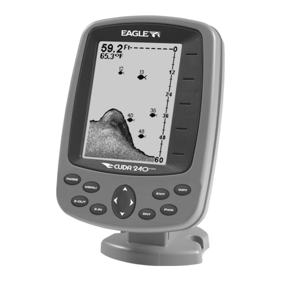
Numbers in the photo correspond to key ex- planations below: Eagle Cuda 240 Sonar, front view, showing screen and keyboard. (A close-up of the keyboard can be found at the beginning of Sec. 6) 1. PWR/LIGHT (Power & Light) – The PWR key turns the unit on and off and activates the backlight. -
Page 38: Memory
4. ARROW KEYS – These keys are used to navigate through the menus, make menu selections, move the plotter cursor and sonar chart cursor and enter data. 5. ENT (Enter) – This key allows you to save data, accept values or execute menu commands. - Page 39 Main Menu. Main Menu Commands There are four "basic" Main Menu commands that you'll really want to read more about. They are: • Screen commands ( ): change ONTRAST RIGHTNESS ISPLAY the appearance of the display screen. Use these commands to adjust how the screen looks under various lighting conditions.
-
Page 40: Sonar Menu
Sonar Menu The Sonar Menu contains commands for the major sonar features and options. You access the Sonar Menu by pressing the key one MENU time. You run a command by using ↑ or ↓ to highlight the command and then pressing . - Page 41 • Overlay Data command: chooses what types of information (such as water temperature) to show overlaid on the sonar chart screen. • Sonar Features command: launches the Sonar Features menu which controls many functions and options, including screen color mode, auto depth and sensitivity, surface clarity, noise rejection, Fish I.D....
- Page 42 Sonar chart display options (from left) full sonar chart and split zoom. Sonar chart digital data display option. You can customize how the Sonar Page pictures and other data are dis- played in many ways. We'll discuss all of those features and options in the Advanced Sonar Operation section, but to show you how easy the sonar unit is to operate, the following page contains a simplified, 10- step quick reference that will cover most fish finding situations.
-
Page 43: Basic Sonar Quick Reference
Basic Sonar Quick Reference 1. Mount the transducer and unit. Connect the unit to electric power and the transducer. 2. Launch your boat. 3. To turn on the unit, press and release 4. Head for your fishing grounds. Your unit automatically displays digi- tal depth and surface water temperature in the corner of the screen. -
Page 44: Sonar Operations
Sonar Operations As you can see from the quick reference on the previous page, basic operation is pretty easy, right out of the box. If you are a sonar novice, try operating the unit with the factory defaults until you get a feel for how it's working. As you're learning the basics, there is one setting you might want to tinker with from time to time —... - Page 45 You can change the sensitivity level whether you are in Auto Sensitiv- ity mode or Manual Sensitivity mode. The adjustment method works the same in both modes, but it gives you slightly different results. Adjusting sensitivity in Auto Sensitivity Mode is similar to manually ad- justing a car's speed with the accelerator pedal while cruise control is on.
-
Page 46: Fish Symbols Vs. Full Sonar Chart
NOTE: If you want to change the sensitivity in Manual Mode, first turn off Auto Sensitivity: from the Sonar Page, press |↑ to ENSITIVITY sensitivity setting. When it's set at the desired level, press Important Tip: While you are experimenting and learning, it's possible to scramble the settings so that the sonar picture disappears from your screen. -
Page 47: Other Free Training Aids
Aside from being just plain fun, this program can help you learn both basic and advanced operations without burning boat fuel! Eagle is the first sonar manufacturer to provide this type of training tool for customers. - Page 48 Notes...
-
Page 49: Section 4: Sonar Options & Other Features
Section 4: Sonar Options & Other Features Material in this section is arranged in alphabetical order. ASP (Advanced Signal Processing) The ASP feature is a noise rejection system built into the sonar unit that constantly evaluates the effects of boat speed, water conditions and interference. -
Page 50: Alarms
3. Press ↓ or ↑ to select a setting, then press 4. To return to the previous page, press Alarms This unit has three different types of sonar alarms. The first is a Fish Alarm. It sounds when the Fish I.D. feature determines that an echo is a fish. -
Page 51: Zone Alarm
3. Press ↑ or ↓ until the depth is correct, then press 4. Press ← to HALLOW 5. To turn off the alarm, press ONAR LARMS To switch to a different depth setting, open the Sonar Alarms menu and repeat the instructions in step 3 above. To adjust and turn on the deep alarm: 1. -
Page 52: Fish Alarm
3. To set the upper boundary for the Zone Alarm, use ← or→ to select , then press ↑ or ↓ to move the top of the bar to the desired depth. PPER 4. To set the lower boundary for the Zone Alarm, use ← or→ to select , then press ↑... -
Page 53: Chart Speed
Chart Speed The rate that echoes scroll across the screen is called the chart speed. The default is maximum; we recommend that you leave the speed set there for virtually all fishing conditions. However, you might consider experimenting with chart speed when you are stationary or drifting very slowly. -
Page 54: Depth Range - Automatic
At left, Sonar Page menu with Depth Cursor command selected. At right, sonar chart with the depth cursor active. The line indicates the The cursor can be moved to any location on the screen, letting you pin- point the depth of a target. 1. -
Page 55: Depth Range - Manual
2. The Depth Range Control Scale appears. Press ↑ or ↓ to select a dif- ferent depth range. A dark bar highlights the selected range. Range numbers in gray cannot be selected. 3. When the new range is selected, press Depth Range - Manual You have complete control over the range when the unit is in the man- ual mode. -
Page 56: Fish I.d. (Fish Symbols & Depths)
When the boat is not moving, fish signals are long, drawn out lines on a normal chart display. FasTrack converts the graph to a vertical bar graph that, with practice, makes a useful addition to fishing at a sta- tionary location. Fish I.D.... -
Page 57: Fishtrack
To turn the Fish I.D. feature on: 1. From the Sonar Page, press 2. Press ↓ to ID S To turn off Fish I.D., repeat these instructions. FishTrack The FishTrack feature shows the depth of a fish symbol when it ap- pears on the display. -
Page 58: Noise Rejection
If you have two signals of equal size, one with gray and the other with- out, then the target with gray is the stronger signal. This helps distin- guish weeds from trees on the bottom, or fish from structure. Grayline is adjustable. Experiment with your unit to find the Grayline setting that's best for you. - Page 59 Overlay Data command on the Sonar Menu, at left. Overlay Data Shown selection menu, right. In this example, we scrolled down the data list to highlight "Ground Speed." When selected, a check mark appears beside the data type. (If you wish, you may now use ↓...
-
Page 60: Ping Speed & Hyperscroll
The selected data type will be displayed in the new size. (To change the font size for another Data Type, press and repeat these steps, be- ginning with step two above.) 3. To return to the previous page, press EXIT Sonar chart with Overlay Data turned on. -
Page 61: Reset Options
At left, Sonar Menu with Ping Speed command selected. Ping Speed Control Bar, right, at default setting. To change Ping Speed: 1. From the Sonar Page, press 2. The Ping Speed Control Bar appears. Press ↑ to increase ping speed; press ↓... -
Page 62: Sensitivity & Auto Sensitivity
1. Press |↓ to |↓ to MENU MENU YSTEM ETUP ESET PTIONS 2. Press ↑ or ↓ to 3. All the menus are cleared and all options are returned to the factory settings. System Menu with Reset Options command selected. Sensitivity &... -
Page 63: To Turn Auto Sensitivity Back On
The control bar used to adjust sensitivity up or down is the same whether the unit is in the automatic or manual mode. In automatic you can adjust sensitivity up to 100 percent but the unit will limit your minimum setting. In auto, the unit will continue to make small ad- justments, allowing for the setting you selected. -
Page 64: Set Keel Offset
Tip: For quicker sensitivity adjustments, try leaving the Sensitivity Control Bar on the screen as the chart scrolls. You can see the changes on the screen as you press the up or down arrows. This is handy when there's a lot of clutter in the water, and you are matching the sensitivity to rapidly changing water conditions. -
Page 65: Sonar Color Mode
2. The Keel Offset dialog box appears with a plus (+) sign at the front of the box. 3. Press ↑ until the displayed number is + 1.5, then press depth indicators now accurately show the water depth from surface to bottom. -
Page 66: Split Zoom Sonar Chart
Full Sonar Chart. The Overlay Data (depth and water temperature) are each set to a different text size. Split Zoom Sonar Chart A split chart shows the underwater world from the surface to the bot- tom on the right side of the screen. The left side shows an enlarged ver- sion of the right side. -
Page 67: Sonar Simulator
Sonar Simulator This unit has a built-in simulator that lets you run it as if you were on the water. All sonar features and functions are useable. When in simulator mode, you will see [Simulator Mode] in the Sonar Page title bar. -
Page 68: Surface Clarity
Sonar Menu with Stop Chart command selected. The box is unchecked, indicating that the chart is scrolling across the screen. Surface Clarity The markings extending downward from the zero line on the chart are called "surface clutter." These markings are caused by wave action, boat wakes, temperature inversion and more. -
Page 69: Zoom & Zoom Bar
Zoom & Zoom Bar "Zooming" the display is used to enlarge small detail, fish signals and the bottom with its associated structure. The 2X zoom doubles the size of all echoes on the screen. The 4X zoom quadruples the size of the echoes. You can also turn on a zoom bar on the far right side of the screen;... - Page 70 Notes...
-
Page 71: Section 5: Sonar Troubleshooting
Section 5: Sonar Troubleshooting If your unit is not working, or if you need technical help, please use the following troubleshooting section before contacting the factory customer service department. It may save you the trouble of returning your unit for repair. For contact information, refer to the last page, just inside the back cover of this manual. - Page 72 This causes the sonar to automatically increase its Discrimination or noise rejection feature. This can cause the unit to eliminate weaker signals such as fish or even structure from the display. 3. The water may be deeper than the sonar's ability to find the bottom. If the sonar can't find the bottom signal while it's in the automatic mode, the digital sonar display will flash continuously.
- Page 73 NOISE A major cause of sonar problems is electrical noise. This usually ap- pears on the sonar's display as random patterns of dots or lines. In se- vere cases, it can completely cover the screen with black dots, or cause the unit to operate erratically, or not at all.
- Page 74 Notes...
-
Page 75: Section 6: Basic Gps Operations
BUT, if you just can't wait to get outside, turn to the one-page Quick Reference on page 79. Keyboard Eagle Cuda 240, close-up of unit's keyboard. 1. PWR/LIGHT (Power & Light) – The PWR key turns the unit on and off and activates the backlight. -
Page 76: Power/Lights (Turn Unit On And Off)
5. ENT/ICONS (Enter & Icons) – This key allows you to save data, ac- cept values or execute menu commands. It is also used to create event marker icons. 6. EXIT – The Exit key lets you return to the previous screen, clear data or erase a menu. - Page 77 Main Menu. The Main Menu commands and their functions are: Screen command: changes the contrast or brightness of the display screen. Sounds command: enables or disables the sounds for key strokes and alarms and sets the alarm style. Alarms command: turns GPS or sonar alarms on or off and changes alarm thresholds.
-
Page 78: Sonar
Pages The unit has four GPS Page displays that represent the four major oper- ating modes. They are the Satellite Status Page, the Navigation Page, Plotter Page and the Position Page. They are accessed by pressing , then using ↑ or ↓ to select a Page. (Clear the Pages |←... - Page 79 Satellite Page. Left view indicates unit has not locked on to any satel- lites and does not have a fix on its position. Center view shows satel- lites being scanned. Right view shows satellite lock-on with a 3D posi- tion acquired (latitude, longitude and altitude.) This screen shows a graphical view of the satellites that are in view.
-
Page 80: Navigation Page
Navigation Page This screen has a compass rose that not only shows your direction of travel, but also the direction to a recalled waypoint. To get to the Navi- gation Page: Press The navigation screen looks like the one below when you're not navi- gating to a waypoint or following a route or trail. - Page 81 Speed (ground speed) is the velocity you are making over the ground. (If you wish, you can customize the Speed window to display Closing Speed instead. Closing Speed is also known as velocity made good. It's the speed that you're making toward the waypoint. For instructions, see the Customize Page Displays entry in Sec.
-
Page 82: Position Page
Current track or heading, shown in degrees Cross track error range (off course indicator) Trail line Left cross track error line Navigation information displays Navigation Page, backtracking a trail while creating a new trail. In the example figure above, the driver is headed north (a 12º track) toward a waypoint 12º... -
Page 83: Plotter Page
The Position Page can be fully customized. The lower window can display ten of 22 types of navigation information. For customization instructions see the Customize Page Displays topic in Sec. 7, System and GPS Setup Options. Some of the popular information displays include: Altitude is height above sea level, not ground level. - Page 84 The arrow in the center of the screen is your present position. It points in the direction you're traveling. The flashing line extending from the back of the arrow is your plot trail, or path you've taken. The plotter's zoom range is the distance across the screen. This number shows in the lower right corner of the screen.
-
Page 85: Gps Quick Reference
Start outdoors, with a clear view of the open sky. As you practice, try navigating to a location at least a few blocks away. While you're learning, navigation in too small an area will constantly trigger arrival alarms. 1. Install the unit. (See complete installation details beginning on page 9.) 2. -
Page 86: Viewing The Plotter: Zoom & Cursor Arrow Keys
Viewing the Plotter: Zoom & Cursor Arrow Keys The plotter is presented from a bird's eye view perspective. The current zoom range shows in the lower right corner of the screen. 1. Press the key (zoom in) to move in closer and see greater detail in a smaller geographic area. -
Page 87: Cancel Navigation
Navigate to cursor. In this example, the cursor has selected waypoint 004. 3. Press and the Cuda 240 will begin navigating to the cur- MENU sor location. The Plotter Page will display a dotted line from your current position to the cursor position. -
Page 88: Find Your Current Position
The Cuda 240 stops showing navigation information. Find Your Current Position Finding your current position is as simple as turning Cuda 240 on. Un- der clear sky conditions, the unit automatically searches for satellites and calculates its position in approximately one minute or less. NOTE: "Clear sky"... -
Page 89: Find Distance From Point To Point
Find Distance From Point to Point You can also measure distance between two other points on the plotter. 1. While on the Plotter Page press: 2. Center your cursor over the first position. (A rubber band line ap- pears, connecting your current position to the cursor's location.) Press to set the first point, and the rubber band line disappears. - Page 90 Sequence for setting a waypoint. Step 1: while traveling, quickly press WPT twice to call up Find Waypoint screen (shown at left) and set a point. Step 2: a message says the waypoint has been saved (shown cen- ter). Step 3: vehicle continues on its way; number waypoint symbol is visible on plotter (shown at right).
-
Page 91: Delete A Waypoint
previous page display. The waypoint is saved and automatically given a name with a sequential number, such as "waypoint 001." The waypoint symbol and number appear on the plotter and in the waypoint list. Create Waypoint by Average Position This feature sets a waypoint at the current position after taking several position readings and averaging them. -
Page 92: Edit A Waypoint (Name, Symbol Or Position)
To delete a waypoint from the plotter: 1. Use the arrow keys to select the waypoint with the cursor. 2. Press |→ to ous page and clear the cursor, press To delete all waypoints at one time: press |↓ to ETUP ELETE to the previous page, press... - Page 93 You will use the Find Waypoint commands to choose a waypoint you want to navigate to, or to choose one for editing. 1. Press . To look up the nearest waypoint, just press down the list to find the desired waypoint; .
-
Page 94: Navigate To A Waypoint
Plotter screen showing Find Waypoint. 7. To clear the search and return to the last page displayed, press . (Before you completely exited out of the Search menus, you EXIT EXIT could have gone looking for another place.) Navigate To a Waypoint You can select any waypoint visible on the Plotter Page with the cursor, then use the Navigate to Cursor command (we described how to do that earlier in this section). -
Page 95: Set Man Overboard (Mob) Waypoint
Course line (dotted) Off course range, set at 0.20 mile Navigation Page, navigating toward a waypoint and leaving a trail. Set Man Overboard (MOB) Waypoint One of boating's most terrifying events is having a friend or family member fall overboard. This situation can be deadly on any body of wa- ter —... -
Page 96: Trails
Navigating to Man Overboard: Navigation Page, left and center, and Plotter Page, right. The victim is astern of the vessel; the GPS shows which direction to steer to for the rescue. The man overboard position is also stored in the waypoint list for future reference. - Page 97 To Save a Trail 1. Press MENU MENU Sequence for saving a trail and beginning a new one. At left, My Trails command. Center, the Trails Menu. The arrow to the right of Trail 3 indicates the trail is "active," and the check to the left indicates the trail is visible on the plotter display.
-
Page 98: Delete A Trail
You can save and recall up to 10 different plot trails. Tip: Another quick way to stop recording one trail and begin a new one is to use the New Trail command: Press RAILS Caution: You also have the option of completely turning off trail record- ing, under the trail Options command. -
Page 99: Edit A Trail Name
Edit a Trail Name To edit a trail name: press . Press ↑ or ↓ to change the first character, then press → name| ENT|ENT to the next character and repeat until the name is correct. Press then EXIT EXIT EXIT Tip: You can quickly call up the Edit Trail menu by selecting a trail on... -
Page 100: Visual Trailing
tween them is "navigating a trail" follows a trail forward (from start to end) while "backtracking" follows a trail in reverse (from end to start.) When hiking at walking speed with a hand-held GPS, we often just use visual back trailing because it is a bit better at following each little turn on a foot path. - Page 101 Figure 1. Figure 2. Figure 4. Figure 3. Navigate a trail menu sequence: Fig. 1, My Trails command. Fig. 2, Trails Menu. Fig. 3, Edit Trail Menu. Fig. 4, Edit Route Menu with Navigate command highlighted for Trail 1. A trail is always converted to a "route"...
-
Page 102: Navigate A Back Trail (Backtrack, Or Reverse)
Trail point Present position arrow Navigate trail, plotter views: at left boater is heading straight toward trail point 3. Center, when the point is reached, Arrival Alarm goes off and the steering arrow points toward next trail point. At right, boater has reached point 3 and has turned northeast to follow trail to point 4. -
Page 103: Icons
3. Press → to ELETE 4. Press ↓ to AVIGATE begins showing navigation information along the trail, in reverse. NOTE: If you are already located at or near the end of your trail, the arri- val alarm will go off as soon as you hit Enter. Just press clear the alarm and proceed. -
Page 104: Create Icon At Current Position
Cursor selects icon location, left; Select Icon Symbol menu, center; Boat Ramp icon on plotter, right. (Cursor has been moved for clarity.) Create Icon at Current Position 1. While you are traveling, press Icon Symbol" menu. 2. Press ← or ↑ or → or ↓ to select your icon symbol, then press The icon appears on the plotter. -
Page 105: Navigate To An Icon
The Delete All Icons command will ask if you are sure. Press ← to . All icons will be deleted from the plotter. The Delete by Symbol command will launch the Select Symbol menu. Press ← or ↑ or → or ↓ to select the icon symbol to delete, then press . - Page 106 Route Planning command on Main Menu, left, will open the Route List screen, right. 2. Press ↓|↓|↑ or ↓ to route name| |↓ to |↓ to OUTE END . The Plotter Page appears with the cursor showing. LOTTER Edit Route menu, left. Edit Route Waypoints menu, right, with Add From Plotter command selected.
-
Page 107: Delete A Route
Route creation sequence: At left, the Plotter Page shows the waypoints we want to visit in our route. Set the first route point at waypoint (001). Center, move cursor to the next waypoint in the route and press Enter. Waypoint added message appears. Right, continue adding way- points until you reach the end of the route. -
Page 108: Edit A Route
Edit a Route You can edit the route name if you wish. 1. From the AVIGATION press |↓ to MENU MENU 2. Press ↓ to route name| 3. Press ↑ or ↓ to change the first character, then press → to move the cursor to the next character and repeat until the name is correct, then press Return... -
Page 109: Navigate A Route In Reverse
Route Planning command on Main Menu, left; Routes menu, center; Edit Route menu, right. Navigate command is selected. 2. Press ↓ to select route name| 3. Upon arrival at your destination, cancel navigation: press |↓ to MENU MENU The following figures show what the Navigation Page and Plotter Page look like while navigating a route. -
Page 110: Utilities
Figure 4. Navigating along a route: Figs. 1 & 4 show the Plotter Page (top) and Navigation Page (bottom) while running a route. Boater is heading straight for waypoint 3. In Figs. 2 & 5, the traveler has arrived at Wpt 3;... -
Page 111: Section 7: System & Gps Setup Options
Section 7: System & GPS Setup Options Alarms This unit has several GPS alarms. The factory default setting has all the alarms turned on. You can turn the alarms off and on and change their distance settings. You can set an arrival alarm to flash a warning message and sound a tone when you cross a preset distance from a waypoint. -
Page 112: Auto Satellite Search
3. To change distance settings, scroll ↓ or ↑ to select the desired cate- gory, then press →| to change the first character, then press → to the next character and repeat until the name is correct. 4. When your adjustments are finished, return to the last page dis- played by repeatedly pressing IMPORTANT ALARM NOTES: Anchor Alarm - The anchor alarm may be triggered even when... -
Page 113: Coordinate System Selection
GPS Auto Search on the Satellite Status Menu. You can force the unit to immediately kick into auto search mode. Here's how: 1. Press and switch to the Satellite Status screen. PAGES 2. Press |↓ to MENU Coordinate System Selection The Coordinate System Menu lets you select the coordinate system to use when displaying and entering position coordinates. -
Page 114: To Setup Loran Td
and tenths of a second (36° 28' 40.9"). It can also show position in: UTM (Universal Transverse Mercator) projection; MGRS (Standard); MGRS (Standard + 10); Map Fix; Loran TD; British, Irish, Finnish, German, New Zealand, Swedish, Swiss, Taiwan, Greek and Military grids. UTM's are marked on USGS topographic charts. -
Page 115: Map Fix
Map Fix Map Fix is used with charts or maps. This system asks for a reference position in latitude/longitude, which you take from a marked location on the map. It then shows the present position as distance on the map from that reference point. -
Page 116: Customize Page Displays
Press ↓ to ELECT point list. Select the waypoint that you saved the reference point under and press . The unit displays a waypoint information screen with the command the Configure Map Fix menu. Finally, press Now press ↑ to OORD . -
Page 117: Simulating Trail Or Route Navigation
GPS Setup Menu, left; GPS Simulator menu, right. Make the desired settings, then turn the simulator on by highlighting GPS S IMULATOR erase this menu. A message and tone appear periodically, warning you that the simulator is on. To turn the simulator off, repeat the above steps or turn the unit off. -
Page 118: Hide Gps Features
Tip: You can pick any spot on the plotter to begin your simulation ses- sion by using the Initialize GPS command. This makes your unit think it's located at the position you select. See it's entry following the entry for Hide GPS Features. Hide GPS Features If there is no GPS antenna/receiver module attached to this unit, the GPS menus and features can be hidden from view with this command. -
Page 119: Plotter Orientation
the present position to the destination waypoint. As you travel toward the destination, the unit automatically begins zooming in — one zoom range at a time — always keeping the destination on the screen. To turn this feature on, from the Plotter Page, press |↓... -
Page 120: To Select Data For Display
First, press PAGES press EXIT To select data for display: 1. From the Plotter or Sonar page, press 2. Press ↓ or ↑ to select Data Type| Overlay Data command on the Sonar Menu, at left. Overlay Data Shown selection menu, right. In this example, we scrolled down the data list to highlight "Ground Speed."... -
Page 121: To Change Displayed Data Font Size
2. Press ↓ or ↑ to select Data Type| pears from the top of the list and reverts to its previous, unchecked po- sition. (If you wish, you may now use ↓ or ↑ to select other Data Types to turn off.) 3. -
Page 122: Pop-Up Help
Pop-up Help Help is available for virtually all of the menu labels on this unit. By highlighting a menu item and leaving it highlighted for a few seconds, a "pop-up" message appears that describes the function of the menu item. This feature is on by default. -
Page 123: Reset Options
1. Press MENU MENU 2. Press EXIT EXIT Reset Options This command is used to reset all features, options and settings to their original factory defaults. This is useful when you have changed several settings and want to return the unit to basic automatic operation. 1. -
Page 124: Set Language
To adjust the display's brightness: Press ↓ to RIGHTNESS scale is minimum brightness; the right end is maximum brightness. To adjust the screen's display mode: Press ↓ to ISPLAY Set Language This unit's menus are available in 10 languages: English, French, Ger- man, Spanish, Italian, Danish, Swedish, Russian, Dutch and Finnish. -
Page 125: Show Waas Alarm
Software Version Information From time to time, Eagle updates the operating system software in some of its products. These software upgrades are usually offered to customers as free downloads from our web site, www.eaglesonar.com. -
Page 126: Sounds And Alarm Sound Styles
At left, Main Menu with Software Information command selected. At right, the Software Information screen. 1. Press MENU MENU 2. Read the information displayed on the screen. 3. To return to the last page displayed, press Sounds and Alarm Sound Styles Sounds triggered by key strokes and alarms can be adjusted: You first press MENU... -
Page 127: Track Smoothing
To set Alarm Sounds: Press ↓ to lighted, press to check it (turn on) and uncheck it (turn off). After the option is set, press To set Alarm Volume: The left end of the scale is low volume; the right end is high volume. Af- ter the option is set, press Press ↓... -
Page 128: Delete All Trails
Main Menu, left, Trails Menu, center, Trail Options, right. Delete All Trails To remove all of the trails from memory: from the Trails Menu, press → |← to ELETE Update Trail Option This menu lets you change the way the trail updates occur. WARNING: If you uncheck the Update Trail option, automatic trail creation and recording will be turned off. -
Page 129: Delete Trail
With one of the Update Criteria selected, use the cursor arrows to highlight either the . Press ↑ or ↓ to change the first character, then press → to press the next character and repeat until the entry is correct. Press return to the Trail Options Menu. -
Page 130: Trail Visible/Invisible And Other Trail Options
Trail Visible/Invisible and Other Trail Options The name, maximum number of points in the trail, activity, and visi- bility are all changed on the Edit Trail menu screen. The Active setting determines whether or not the unit is recording new points for a par- ticular trail. -
Page 131: Sec. 8: Supplemental Material
Section 8: Supplemental Material FCC Compliance This device complies with Part 15 of the U.S. Federal Communi- cations Commission (FCC) Rules. Operation is subject to the fol- lowing two conditions: (1) this device may not cause harmful in- terference, and (2) this device must accept any interference re- ceived, including interference that may cause undesired opera- tion. - Page 132 Notes...
-
Page 133: Index
Accessories, 1, 5, 23, 24 Sec. 2, Installation & Accessories, 9 Alarm Clock, 104 Alarms, 33, 44, 45, 46, 71, 79, 94, 95, 97, 104, 105, 106, 111 Anchor Alarm, 105, 106 Antenna, 3, 5, 65, 67, 79, 112, 125 Arrival Alarm, 79, 94, 95, 97, 104, 105, 106, 111 Backlights / Lighting, 2, 31, 69... - Page 134 111, 115 Create and Save, 99 Delete, 101 Navigate, 102, 103 Satellite Search, 106 Searching, 82, 83, 84, 86, 87, 88, 89 Set Local Time, 106, 118 Simulator, 4, 33, 61, 110, 111, 112 Software Version Information, 119 Sounds, 120 Status Menu, 107 Sun/Moon Rise &...
- Page 135 THIS IS A LEGAL AGREEMENT BETWEEN THE END-USER WHO FIRST PURCHASES THIS PRODUCT AS A CONSUMER ITEM FOR PERSONAL, FAMILY, OR HOUSEHOLD USE ("YOU") AND EAGLE ELECTRONICS, A DIVISION OF LEI, THE MANUFACTURER OF THIS PRODUCT ("WE", "OUR", OR "US"). USING THE PRODUCT ACCOMPANIED BY THIS LI- CENSE AGREEMENT CONSTITUTES ACCEPTANCE OF THESE TERMS AND CONDITIONS.
- Page 136 DATABASES LIMITED WARRANTY "We", "our", or "us" refers to Eagle Electronics, a division of LEI, the manufac- turer of this product. "You" or "your" refers to the first person who purchases the product as a consumer item for personal, family, or household use. The Da- tabases Limited Warranty applies to the one or more databases that your prod- uct may contain.
- Page 137 EAGLE ELECTRONICS FULL ONE-YEAR WARRANTY "We," "our," or "us" refers to EAGLE ELECTRONICS, a division of LEI, the manufac- turer of this product. "You" or "your" refers to the first person who purchases this product as a consumer item for personal, family, or household use.
-
Page 138: How To Obtain Service
8 a.m. to 5 p.m. Central Standard Time, M-F Eagle Electronics may find it necessary to change or end our shipping policies, regulations, and special offers at any time. We reserve the right to do so without notice. -
Page 139: Accessory Ordering Information For All Countries
1. Always use the original shipping container and filler material the product was packed in. 2. Always insure the parcel against damage or loss during shipment. Eagle does not assume responsibility for goods lost or damaged in transit. 3. For proper testing, include a brief note with the product describing the problem. -
Page 140: Visit Our Website
Eagle Pub. 988-0152-011 Printed in USA 091903 Visit our web site: www.eaglesonar.com © Copyright 2003 All Rights Reserved Eagle Electronics...
Need help?
Do you have a question about the Cuda 240 S/GPS and is the answer not in the manual?
Questions and answers