
Related Manuals for Eagle Cuda 250


Summary of Contents for Eagle Cuda 250
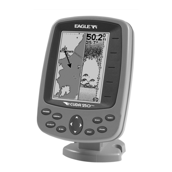
- Page 1 Pub. 988-0152-101 www.eaglesonar.com & Cuda 250i S/Map Fish-finding Sonar & GPS Installation and Operation Instructions www.Busse-Yachtshop.de email: info@busse-yachtshop.de...
- Page 2 Ltd. Exit Authority and eXitSource are trademarks of Zenrin Co. Ltd. Eagle Electronics may find it necessary to change or end our policies, regulations, and special offers at any time. We reserve the right to do so without notice. All features and specifications subject to change without notice.
-
Page 3: Table Of Contents
Table of Contents Section 1: Read Me First!............1 Capabilities and Specifications: Cuda 250 S/Map ......3 How Your Sonar Works ..............5 How Your GPS Works ..............6 Introduction to GPS and WAAS........... 7 How to use this manual: typographical conventions ....9 Arrow Keys ................ - Page 4 Main Menu ................45 Sonar Menu ................46 Pages ................... 48 Sonar Quick Reference ............50 Sonar Operations ................ 51 Fish Symbols vs. Full Sonar Chart ........55 Other Free Training Aids ............55 Section 4: Sonar Options & Other Features ..... 57 ASP...
- Page 5 Stop Chart ................... 79 Surface Clarity ................80 Zoom Pan..................82 Section 5: Sonar Troubleshooting ........83 Section 6: Basic GPS Operations ......... 87 Keyboard ..................87 Power/lights on and off ............... 88 Main Menu .................. 89 Pages ................... 90 Sonar Page ................
- Page 6 Delete an Icon ............... 117 Navigate to an Icon ............... 118 Routes..................119 Create and Save a Route ............119 Delete a Route ............... 122 Edit a Route ................122 Navigate a Route..............123 Trails ..................125 Delete a Trail ................ 125 Edit a Trail Name ..............
- Page 7 Map Data................... 141 Earth Map Detail ..............141 Pop-up Map Info..............141 Fill Water With White ............141 Map Overlays (Range Rings; Lat/Long Grid) ...... 142 Map Datum Selection ............... 142 Map Detail Category Selection..........143 Map Orientation ............... 144 Overlay Data ................
- Page 8 WARNING! A CAREFUL NAVIGATOR NEVER RELIES ON ONLY ONE METHOD TO OBTAIN POSITION INFORMATION. CAUTION When showing navigation data to a position (waypoint), a GPS unit will show the shortest, most direct path to the waypoint. It provides navigation data to the waypoint regardless of obstructions.
-
Page 9: Section 1: Read Me First
GPS receiver. First, we want to thank you for buying a Eagle sonar/GPS unit. Whether you're a first time user or a professional fisherman, you'll dis- cover that your unit is easy to use, yet capable of handling demanding navigation and sonar tasks. - Page 10 This section features a one-page Sonar Quick Reference. (If you've al- ready jumped ahead and figured out how to install the unit yourself, and you just can't wait any longer, turn to the Quick Reference on page 50 and head for the water with your unit!) When you come to a sonar menu command on the unit's screen, you can look it up in the manual by skimming over the table of contents, looking it up in the manual's index, just flipping through Section 3 or scanning...
-
Page 11: Capabilities And Specifications: Cuda 250 S/Map
It's important to us (and our power users), but, if you don't care how many watts of power the unit has, or how many waypoints it can store, skip ahead to important information on how sonar works, on page Cuda 250 S/Map Capabilities and Specifications: General Display:...... - Page 12 Sonar sounding depth capability: ... 600 feet (180 meters). Actual capability de- pends on transducer configuration and in- stallation, bottom composition and water con- ditions. All sonar units typically read deeper in fresh water than in salt water. Depth display:....Continuous display. Audible alarms: .....
-
Page 13: How Your Sonar Works
NOTICE! The storage and operation temperature range for your unit is from -4 degrees to +167 degrees Fahrenheit (-20 degrees to +75 degrees Celsius). Extended storage or operation in temperatures higher or lower than specified will damage the liquid crystal display in your unit. -
Page 14: How Your Gps Works
You can replay this sonar log in the unit using the Sonar Simulator func- tion. You can save several different sonar log files, erase 'em and record new ones, over and over again. How Your GPS Works You'll navigate faster and easier if you understand how this unit scans the sky to tell you where you are on the earth —... -
Page 15: Introduction To Gps And Waas
Think of this data storage like the hard drive memory in a computer or a tape in a cassette tape recorder. You can save several different GPS data files, erase 'em and record new ones, over and over again. Introduction to GPS and WAAS Well, now you know the basics of how the unit does its work. - Page 16 The system requires signal reception from three satellites in order to determine a position. This is called a 2D fix. It takes four satellites to determine both position and elevation (your height above sea level — also called altitude). This is called a 3D fix. Three satellites are required to determine a 2D fix.
-
Page 17: How To Use This Manual: Typographical Conventions
beyond basic GPS. So, the FAA has developed a program to boost GPS performance with its Wide Area Augmentation System, or WAAS. The FAA commissioned the system on July 11, 2003. WAAS is designed to increase GPS accuracy to within 7.6 meters vertically and horizontally, but it consistently delivers accuracies within 1-2 meters horizontal and 2-3 meters vertical, according to the FAA. -
Page 18: Arrow Keys
can skim the instructions and pick out what menu command to use by finding the boldface command text. The following paragraphs explain how to interpret the text formatting for those commands and other in- structions: Arrow Keys The arrow keys control the movement of dotted cross-hair lines on your plotter screen called the cursor. - Page 19 4. The wait message disappears and the unit begins showing navi- gation information along the trail. Now, begin moving and follow your unit's directions. Translated into complete English, step 1 above would mean: "Start on the Plotter Page. Press the Menu key twice. Next, repeatedly press (or press and hold) the down arrow key to scroll down the menu and select (highlight) the My Trails menu command.
- Page 20 Notes www.Busse-Yachtshop.de email: info@busse-yachtshop.de...
-
Page 21: Section 2: Installation & Accessories
Section 2: Installation Preparations You can install the sonar and GPS systems in some other order if you prefer, but we recommend this installation sequence: CAUTION: You should read over this entire installation section before drill- ing any holes in your vehicle or vessel! 1. -
Page 22: Recommended Tools And Supplies
Your Skimmer transducer typically comes packaged with a one-piece stainless steel bracket for mounting it to the transom of your boat. The optional trolling motor mount uses a one-piece plastic bracket with an adjustable strap. These are "kick-up" mounting brackets. They help pre- vent damage if the transducer strikes an object while the boat is moving. -
Page 23: Selecting A Transducer Location
sandpaper, specially formulated epoxy adhesive available from LEI (see ordering information on the inside back cover). A sandwich hull also requires polyester resin. Selecting a Transducer Location 1. The location must be in the water at all times, at all operating speeds. 2. -
Page 24: How Low Should You Go
5. If possible, route the transducer cable away from other wiring on the boat. Electrical noise from engine wiring, bilge pumps and aerators can be displayed on the sonar's screen. Use caution when routing the transducer cable around these wires. CAUTION: Clamp the trans- ducer cable to transom near the transducer. -
Page 25: Shoot-Thru-Hull Vs. Transom Mounting
Transom Transducer centerline Hull bottom Align transducer centerline with hull bottom. However, there are times when you may need to adjust the transducer slightly higher or lower. (The slots in the mounting brackets allow you to loosen the screws and slide the transducer up or down.) If you fre- quently lose bottom signal lock while running at high speed, the trans- ducer may be coming out of the water as you cross waves or wakes. - Page 26 Typically, shoot-thru-hull installations give excellent high speed opera- tion and good to excellent depth capability. There is no possibility of transducer damage from floating objects, as there is with a transom- mounted transducer. A transducer mounted inside the hull can't be knocked off when docking or loading on a trailer.
- Page 27 Align plastic ratchets in bracket. 2. Aligning the transducer on the transom. Slide the transducer between the two ratchets. Temporarily slide the bolt though the transducer assembly and hold it against the transom. Looking at the transducer from the side, check to see if it will adjust so that its face is parallel to the ground.
- Page 28 Ratchets Insert bolt and check transducer position on transom. 3. Assembling the transducer. Once you determine the correct posi- tion for the ratchets, assemble the transducer as shown in the fol- lowing figure. Don't tighten the lock nut at this time. Metal washer Rubber...
- Page 29 Mark the center of each slot for the mounting screw pilot holes. You will drill one hole in the center of each slot. Drill the holes using the #29 bit (for the #10 screws). Transom Transom Position transducer mount on transom and mark mounting holes. Side view (left) and seen from above (right).
- Page 30 Adjust the transducer so that it's parallel to the ground and tighten the nut until it touches the outer washer, then add 1/4 turn. Don't over tighten the lock nut! If you do, the transducer won't "kick-up" if it strikes an object in the water. Bottom hull Flat-bottom hull...
- Page 31 7. Make a test run to determine the results. If the bottom is lost at high speed, or if noise appears on the display, try sliding the trans- ducer bracket down. This puts the transducer deeper into the water, hopefully below the turbulence causing the noise. Don't allow the transducer bracket to go below the bottom of the hull! TROLLING MOTOR BRACKET INSTALLATION 1.
- Page 32 Transducer mounted on trolling motor, side view. TRANSDUCER ORIENTATION AND FISH ARCHES If you do not get good fish arches on your display, it could be because the transducer is not parallel with the ground when the boat is at rest in the water or at slow trolling speeds.
- Page 33 Partial fish arches Transducer aimed Transducer aimed too far forward too far back Full fish arch Proper transducer angle Transducer angles and their effects on fish arches. If the arch slopes up – but not back down – then the front of the trans- ducer is too high and needs to be lowered.
-
Page 34: Hulls With Floatation Materials
SHOOT-THRU-HULL PREPARATION Hulls With Floatation Materials The transducer installation inside a fiberglass hull must be in an area that does not have air bubbles in the resin or separated fiberglass lay- ers. The sonar signal must pass through solid fiberglass. A successful transducer installation can be made on hulls with flotation materials (such as plywood, balsa wood or foam) between layers of fiberglass if the material is removed from the chosen area. -
Page 35: Testing Determines Best Location
Remember, the sonar signal must pass through solid fiberglass. Any air bubbles in the fiberglass or the epoxy will reduce or eliminate sonar signals. Testing Determines Best Location Ideally, the shoot-thru transducer should be installed as close to the transom as possible, close to the centerline. This will give you the best performance during high speed maneuvers. - Page 36 True bottom Second bottom Manual range setting Example of a second bottom signal. Unit is in 30 feet of water, with range set at 80 feet and sensitivity set at 87 percent. 2. Next, take the transducer out of the water and place it in the water in the sump of the boat, face down.
-
Page 37: Shoot-Thru-Hull Installation
4. Most people can get good results by following steps 1 through 3, so this step is optional. If you want to make an extra effort to be absolutely sure that your selected location will work under all conditions, make a test run with the boat on plane and observe the bottom signal. - Page 38 Spread epoxy here Sand this surface Orient the Skimmer with the nose facing the bow of the boat. To bow Epoxy transducer to hull. WARNING: Use only the epoxy available from LEI. It has been for- mulated to work with these installation procedures. Other epoxy types may be too thin or may not cure to the right consistency for optimum transducer performance.
-
Page 39: Power And Cable Connections
when you bottom out on the hull. When you're finished, the face of the transducer should be parallel with the hull, with a minimum amount of epoxy between the hull and transducer. 4. Apply a weight, such as a brick, to hold the transducer in place while the epoxy cures. - Page 40 12 volt 3 amp fuse battery Power and transducer connections for the Cuda 250 sonar units (direct battery connection shown). If possible, keep the power cable away from other boat wiring, espe- cially the engine's wires. This will provide the best isolation from elec- trical noise.
-
Page 41: Mounting The Sonar Unit: In-Dash Or Bracket
You can install the sonar unit on the top of a dash with the supplied bracket. It can also be installed in the dash with an optional FM-6 dash-mounting kit. ALWAYS VERIFY DIMENSIONS. Cut along this line In-dash mounting template for Cuda 250. NOTE: This figure is not printed to scale. www.Busse-Yachtshop.de email: info@busse-yachtshop.de... - Page 42 (See the following drawings, which show the dimensions of a mounted Cuda 250 sonar unit.) Holes in the bracket’s base allow wood screw or through-bolt mounting. You may need to place a piece of plywood on the back side of thin pan- els to reinforce the panel and secure the mounting hardware.
- Page 43 107.5 82.7 [4.23] [3.26] [6.26] 12.09 [0.48] 76.9 70.3 Millimeter [3.03] [2.77] [Inch] Front view (left) and side view (right) showing dimensions of the Cuda 250 when mounted on quick release bracket. If you wish, you can fill in the hole around the cable with a good marine sealant compound.
- Page 44 Screw hole Power/transducer cable Cable slot Cuda 250 quick release mounting bracket. Slots in the base allow routing the cable from beneath the mount. Attach the unit to the bracket by first connecting the power/transducer cable. Then, hold the sonar unit vertically and slide it onto the bracket from above.
- Page 45 Bracket front Mount the sonar: slide the unit onto the bracket from above. Depress ratchets to release. Swivel base Adjust viewing angle: use one hand to press and release the spring- loaded ratchets while you move the unit with the other hand. An op- tional GBSA-3 swivel base is shown with the quick release bracket.
-
Page 46: Portable Sonar Installation
The power pack and portable transducers expand the uses for your so- nar. You can use your Cuda 250 sonar unit on your boat or take it to the dock, on a float tube, on an ice fishing trip or use it as a second sonar in a friend's boat. - Page 47 tor and about 6 inches of cable through the opening under the sonar mount. Close the cover, plug the connector into the sonar unit and mount the unit on the built-in bracket. PPP-12 Portable Power Pack with a sonar unit stowed for transport. Turn the unit on.
-
Page 48: Portable Transducer Assembly
If the batteries do lose a charge, you can sometimes restore them by placing them in a warm room or car interior. A better way is to replace them with batteries that have been kept warm. WARNING: Never heat the batteries over an open flame or direct hot air onto them. - Page 49 Tie nylon cord here Screw Suction Bolt Washer Washer Transducer Portable transducer assembly: rear view (left) and side view (right.) Clean the chosen area of the hull before attaching the suction cup. Lo- cate the transducer on the hull as shown in the following figure. Don't allow the bracket to extend below the hull, because water pressure against it can cause the suction cup to come off at speed.
- Page 50 NOTE: For optimum operation, the portable transducer should be adjusted so that it is parallel to the ground. For more information on this, see the earlier segment on Transducer Orientation and Fish Arches. Now that you have your unit installed, move on to Sec. 3, Basic Sonar Operations.
-
Page 51: Section 3: Basic Sonar Operation
Section 3: Basic Sonar Operation Keyboard The unit sounds a tone when you press any key. This tells you the unit has accepted a command. Numbers in the photo correspond to key ex- planations below: Eagle Cuda 250 S/Map. www.Busse-Yachtshop.de email: info@busse-yachtshop.de... - Page 52 1. PWR/LIGHT – The PWR key turns the unit on and off and activates the backlight. 2. PAGES – Pressing this and the arrow keys (4) switches the unit be- tween the different page display screens. 3. MENU – Press this key to show the menus and submenus, which allow you to select a command or adjust a feature.
-
Page 53: Memory
Memory This unit has permanent memory that saves all user settings, even when power is removed. It does not require, nor does it use an internal backup battery, so you never have to worry about replacement batteries. Menus Your sonar unit will work fine right out of the box with the factory default settings. -
Page 54: Sonar Menu
Enable NMEA 183 Output: enables NMEA 0183 output and disables temperature 2, water speed and water distance. For more information, see Cuda addendum, part number 988-0152-082. Alarms: turns sonar and GPS alarms on or off and changes alarm thresholds. Route Planning: used to plan, view or navigate a route. My Trails: shows, creates and deletes plot trails. - Page 55 Sonar Page Menu. Sonar Menu Commands Sensitivity: sets threshold of sonar echoes shown on sonar chart. Auto Sensitivity: automatically adjusts sensitivity based on depth. GrayLine: separates fish and structure near the bottom from the actual bottom and defines bottom composition/hardness. Depth Range: manually sets the depth range shown on sonar chart.
- Page 56 Pages The Cuda 250 has three major Sonar display options. They are the Full Sonar Chart, Split Zoom Sonar Chart and Digital Data. key. Press → to You access display modes by pressing the |↑ PAGES ONAR or ↓ to desired page| .
- Page 57 Full sonar chart (left); split zoom (center); Digital data (right). You can customize how the Sonar Page pictures and other data are dis- played in many ways. We will discuss all of those features and options in the Advanced Sonar Operation section, but to show you how easy the sonar unit is to operate, the following page contains a simplified, 10- step quick reference that will cover most fish finding situations.
-
Page 58: Sonar Quick Reference
Sonar Quick Reference 1. Mount the transducer and unit. Connect the unit to electric power and the transducer. 2. Launch your boat. 3. To turn on the unit, press and release key. 4. Head for your fishing area. Your unit automatically displays digital depth and surface water temperature in the corner of the screen. -
Page 59: Sonar Operations
Sonar Operations As you can see from the quick reference on the previous page, basic operation is pretty easy, right out of the box. If you are a sonar novice, try operating the unit with the factory defaults until you get a feel for it. As you are learning the basics, there is one setting you might want to tinker with from time to time —... - Page 60 Fig. 1 Fig. 2 Bait fish Fish arches Thermocline with fish Fig. 3 Fig. 4 These figures show results of different sensitivity levels on the same location. Fig. 1: Sensitivity at 87 percent, determined by Auto Sensitiv- ity. Typical of full auto mode. Fig. 2: Sensitivity set at 50 percent. Fig. 3: Sensitivity set at 20 percent.
- Page 61 Adjusting sensitivity in Auto Sensitivity Mode is similar to manually ad- justing a car's speed while cruise control is on. You can tell the car to run faster, but when you let off the gas the cruise control automatically keeps you from running slower than the minimum speed setting.
- Page 62 Sonar Menu with Sensitivity command selected (left). Sensitivity Control Bar (right). NOTE: If you want to change the sensitivity in Manual Mode, turn off Auto Sensitivity. From the Sonar Page, press |↓ to MENU ENSI- . Press ↓ or ↑ to pick a different sen- |↑...
-
Page 63: Fish Symbols Vs. Full Sonar Chart
Fish Symbols vs. Full Sonar Chart You may have noticed in the quick reference we used fish arches in full sonar chart mode for our example and not the popular Fish I.D. fish symbol feature. Here is why. Fish I.D. is an easier way for a sonar novice to recognize a fishy signal return when he sees it. - Page 64 For the ultimate training aid, download the free emulator software for your unit. Aside from being fun, the program can help you learn both basic and advanced operations without burning boat fuel! Eagle is the first sonar manufacturer to provide this type of training tool for cus- tomers.
-
Page 65: Section 4: Sonar Options & Other Features
Section 4: Sonar Options & Features ASP (Advanced Signal Processing) The ASP feature is a noise rejection system built into the sonar unit that constantly evaluates the effects of boat speed, water conditions and interference. This feature automatically gives you the best display possible under most conditions. -
Page 66: Alarms
Sonar Features selected (left). In the Sonar Features menu, Noise Rejec- tion is selected with ASP in the default low setting (right). To change the ASP level: 1. From the Sonar Page, press |↓ to MENU ONAR EATURES 2. Press ↓ to OISE EJECTION 3. - Page 67 sound until the bottom goes deeper than 10 feet. The deep alarm works just the opposite. It sounds a warning tone if the bottom depth goes deeper than the alarm's setting. Both depth alarms work only off the digital bottom depth signals. No other targets will trip these alarms. These alarms can be used at the same time or individually.
-
Page 68: Zone Alarm
3. Press ↓ to LARM NABLED 4. Press ↑ to and press EPTH 5. Use ↑ ↓ to change the first digit, then press → to the next digit. Re- peat these steps until the desired depth has been input. Press To switch to a different depth setting, open the Sonar Alarms menu and repeat the instructions in steps 4 and 5 above. -
Page 69: Fish Alarm
To switch to a different depth setting, open the Sonar Alarms menu and repeat the instructions above, beginning with step 2. Fish Alarm Use the fish alarm for a distinctive audible alarm when fish or other suspended objects are detected by the Fish I.D. feature (Fish I.D. must be turned on for the Fish Alarm to work). - Page 70 drifting very slowly. You may achieve better fish signals when you de- crease the chart speed until it matches your speed across the water. If you are at anchor, ice fishing or fishing from a dock, experiment with a chart speed around 50 percent. If you are drifting slowly, try a chart speed around 75 percent.
-
Page 71: Depth Cursor
Depth Cursor The depth cursor consists of a horizontal line with a digital depth box on the right side. The numbers inside the box show the depth of the cursor. Cursor line Depth box Sonar Page menu with Depth Cursor command selected (left). Sonar chart with the depth cursor active (right). -
Page 72: Depth Range - Manual
Sonar Page menu with Depth Range command selected (left). The Depth Range Control Scale (right). 2. The Depth Range Control Scale appears. Press ↑ or ↓ to select a dif- ferent depth range. A dark bar highlights the selected range. Range numbers in gray cannot be selected. -
Page 73: Fastrack
NOTE: The sonar's depth capability depends on transducer installation, water and bottom conditions, among other factors. FasTrack This feature automatically converts all echoes to short horizontal lines on the right side of the screen. The graph on the rest of the screen con- tinues to operate normally. - Page 74 on the screen in place of the actual fish echoes. There are several fish symbol sizes. These are used to designate the relative size between tar- gets. In other words, Fish I.D. displays a small fish symbol when it thinks a target is a small fish, a medium fish symbol on a larger target and so on.
-
Page 75: Fishtrack
To turn the Fish I.D. feature on: 1. From the Sonar Page, press |↓ to MENU ONAR EATURES 2. Press ↓ to ID S EXIT EXIT YMBOLS To turn off Fish I.D., repeat these instructions. FishTrack The FishTrack feature shows the depth of a fish symbol when it ap- pears on the display. -
Page 76: Grayline
Grayline Grayline lets you distinguish between strong and weak echoes. It paints gray on targets that are stronger than a preset value. This al- lows you to tell the difference between a hard and soft bottom. For ex- ample, a soft, muddy or weedy bottom returns a weaker signal, which is shown with a narrow gray line or no gray line at all. -
Page 77: Overlay Data
HyperScroll See the entry on Ping Speed, which controls the HyperScroll feature. Noise Rejection See the entry on Advanced Signal Processing in this section. Overlay Data To change the digital data shown on top of the sonar page: 1. Press |↓... -
Page 78: Ping Speed & Hyperscroll
To turn off displayed data: 1. Press |↓ to MENU VERLAY 2. Press ↓ or ↑ to select Data Type, then press ← → until the checkmark next the selected data type disappears. After you have turned off the data type, you can use ↓ ↑ to select another data type. 3. - Page 79 The increased ping rate allows the screen refresh rate and chart scroll speed to keep pace with the boat as it moves quickly over the water. When using HyperScroll, you may also need to manually decrease the sensitivity for optimum performance. Depending on water depth and other conditions, HyperScroll may cause a second bottom echo to return to the transducer during the next ping cycle or sounding.
-
Page 80: Reset Options
When you boost ping speed and switch into HyperScroll, the width of the FasTrack bar graph display doubles in width at the right side of the screen. This allows you to better see the virtually instantaneous sonar returns, just as you would on a flasher sonar unit. For more informa- tion on FasTrack, see it's entry in this section. -
Page 81: Automatic Sensitivity
High sensitivity levels let you see this detail, but it can also clutter the screen with many undesired signals. Typically, the best sensitivity level shows a good solid bottom signal with Grayline and some surface clutter. Automatic Sensitivity The default sensitivity mode is automatic. The unit bases the sensitiv- ity level on water depth and conditions. -
Page 82: Set Keel Offset
changes on the screen as you press the up or down arrows. This is handy when there is a lot of clutter in the water and you are matching the sensitivity to rapidly changing water conditions. Sonar Menu with Sensitivity command selected (left). The Sensitivity Control Bar (right). - Page 83 If the transducer is 1 foot below the surface and the screen shows the water depth as 30 feet, then the actual depth is 31 feet. On sailboats or other large vessels with deep drafts, the distance be- tween the transducer installation and the keel or lower engine unit can be several feet.
-
Page 84: Sonar Color Mode
Sonar Page. EXIT EXIT Sonar Page & Sonar Chart Display Options The Cuda 250 offers three Sonar chart display options. To choose one, and use the ↑ ↓ keys press to clear any menus, then press... -
Page 85: Split Zoom Sonar Chart
The bottom depth and surface temperature (if the unit is equipped with a temperature sensor or a transducer with a temp sensor built in) show at the top left corner of the screen. The FasTrack™ display shows just to the right of the scale. This changes all echoes into short horizontal bars, replicating a flasher so- nar. -
Page 86: Digital Data/Chart
Split Zoom Sonar Chart. First image (left) shows the left window zoomed to 2X. The second image (right) shows the left window zoomed to 4X. The depth overlay data is set to the default large text size. The water temperature is set to the medium text size. Digital Data/Chart This mode shows nine digital boxes or windows containing (by default): Water Depth, Water Temp, Position Error, Bearing, Distance, Speed,... -
Page 87: Sonar Simulator
Sonar Simulator This unit has a built-in simulator that will allow you to practice as though you were on the water. All sonar features and functions will be useable during a simulation. When in simulator mode, you will see [Simulator Mode] in the Sonar Page title bar. To use the simulator: 1. -
Page 88: Surface Clarity
Sonar Menu with Stop Chart selected. The box is unchecked, indicat- ing the chart is scrolling across the screen. Surface Clarity The onscreen marks scattered at the top of the sonar chart are known as surface clutter. They are caused by wave action, boat wakes, tem- perature inversion and more. - Page 89 Sonar Features menu with Surface Clarity selected. Zoom & Zoom Bar The Zoom in key is used to enlarge small detail, fish signals and the bottom with its associated structure. The 2X zoom doubles the size of all echoes on the screen. The 4X zoom quadruples the size of the echoes.
-
Page 90: Zoom Pan
Sonar Page with normal view (left). Sonar page with view zoomed to 2X (left). Sonar page with view zoomed to 4X (right) Zoom Pan Your unit has the ability to quickly zoom in on any portion of the water column with just the touch of an arrow key. The Zoom Pan feature lets you rapidly move the zoomed area up and down to different depths. -
Page 91: Section 5: Sonar Troubleshooting
Section 5: Sonar Troubleshooting If your unit is not working, or if you need technical help, please use the following troubleshooting section before contacting the factory customer service department. It may save you the trouble of returning your unit for repair. For contact information, refer to the last page, just inside the back cover of this manual. - Page 92 Weak bottom echo, digital readings erratic or no fish signals: 1. Make sure the transducer is pointing straight down. Clean the face of the transducer. Oil, dirt and fuel can cause a film to form on the trans- ducer, reducing its effectiveness. If the transducer is mounted inside the hull, be sure it is shooting through only one layer of fiberglass and that it is securely bonded to the hull.
- Page 93 Try using resistor spark plugs or routing the sonar unit's power and transducer cables away from other electrical wiring on the boat. No fish arches when the Fish I.D. feature is off: 1. Make sure the transducer is pointing straight down. This is the most common problem if a partial arch is displayed.
- Page 94 on the bilge pump and view the sonar display for noise. If no noise is present, turn the pump off, then turn on the VHF radio and transmit. Keep doing this until all electrical equipment has been turned on, their effect on the sonar display noted, then turned off.
-
Page 95: Section 6: Basic Gps Operations
GPS Operations, will discuss other more advanced functions and utilities. Before you turn on the Cuda 250 and find where you are, it is a good idea to learn about the different keys, the five GPS Pages and how they all work together. -
Page 96: Power/Lights On And Off
4. ARROW KEYS – These keys are used to navigate through the menus, make menu selections, move the map cursor and sonar chart cursor and enter data. 5. ENT – The Enter key allows you to save data, accept values or exe- cute menu commands. -
Page 97: Main Menu
The Cuda 250 has a Main Menu, which contains function commands and setup option commands. The instructions in this section will deal with functions, the basic commands that make the Cuda 250 do some- thing. The unit will work fine for this right out of the box with the de- fault settings. - Page 98 Route Planning: used to plan, view or navigate a route. My Trails: shows, hides, creates and deletes plot trails. Also used to navigate or backtrack a trail. Cancel Navigation: turns off the various navigation commands. Used to stop navigating after you have reached your destination. Sonar Setup: sets various sonar options.
-
Page 99: Sonar Page
Pages Menu, showing Map display options. Sonar Page The Sonar Page displays the sonar chart, a view of the water column from the surface to the bottom. The chart scrolls across the screen from right to left, displaying signal echoes that represent fish, structure and the bottom. - Page 100 Satellite Page. First page (left) indicates unit has not locked on to any satellites and does not have a fix on its position. The second page (cen- ter) shows satellites being scanned. The last page (right) shows satel- lite lock-on with a 3D position. The Satellite Page screen shows a graphical view of satellites the unit is tracking.
-
Page 101: Navigation Page
rently has. The smaller the position error number, the better (and more accurate) the fix is. If the position error flashes dashes, then the unit hasn't locked onto the satellites, and the number shown isn't valid. The Satellite Status Page has its own menu, which is used for setting various options. - Page 102 Track or compass heading indicator, showing direction of travel Compass rose Present Trail line position arrow Navigation information displays Navigation Page, recording a trail, traveling north. The page looks like this when the unit is not navigating to a waypoint, following a route, or backtracking a trail.
- Page 103 It is the speed you are making toward the waypoint. For more detailed instructions, see the Customize Page Displays entry in Sec. 8.) Track is the heading or the current direction you are traveling. Bearing is the direction of a line-of-sight from your present position to the des- tination.
-
Page 104: Full Map Page
Current track or Waypoint symbol heading, shown Compass in degrees bearing to destination Cross track Bearing error range arrow (off course indicator) Trail line Course line Left cross track error line Cross track error range Navigation (off course information indicator) displays Navigation Page, backtracking a trail while creating a new trail. - Page 105 The Cuda 250 includes high-detail mapping of lakes, rivers, the Great Lakes and coastal waters in the United States with enhanced shoreline detail and nav aids. Its medium-detail U.S. maps contain: all incorpo- rated cities;...
-
Page 106: Map With Sonar Page
more than 60,000 navigation aids and 10,000 wrecks and obstructions in U.S. coastal and Great Lakes waters NOTE: If you have a Cuda 250i, your unit has medium-detail maps of the entire world. The Map Page has its own menu, which is used for several functions and for setting various options. -
Page 107: Gps Quick Reference
1. Install the unit. (See complete installation details beginning on page 9.) 2. To turn on the Cuda 250, press and release key. 3. Opening screen displays the moving map at the 4,000-mile zoom range. -
Page 108: Find Your Current Position
9. At destination, Arrival Alarm goes off; to clear it, press . Cancel EXIT ← to Y navigation: press |↓ to MENU MENU ANCEL AVIGATION 10. Return to Wpt 1 by Backtrack Trail. Press |↓ to MENU MENU . Press ↓ to Trail 1| |↓... - Page 109 When you are traveling, the map will automatically move as you move. This keeps your current location roughly centered on the screen. You can manually pan or scroll the map northward, southward, east- ward or westward by using the arrow keys, which launch the cursor crosshairs.
-
Page 110: Selecting Any Map Item With The Cursor
Selecting Any Map Item With the Cursor 1. Use the zoom keys and the arrow keys to move around the map and find the item you wish to select. 2. Use the arrow keys and center the cursor crosshairs on the desired ob- ject. - Page 111 Step 1. Step 2. Step 3. Step 4. Sequence for setting a waypoint. Step 1: while traveling, quickly press WPT twice to call up Find Waypoint screen (seen in Step 2) and set a point. Step 3: a message says the waypoint has been saved. Step 4: ve- hicle continues on its way;...
-
Page 112: Create Waypoint On Map
Create Waypoint on Map 1. Use the arrow keys to move the cursor to the place where you want to make a waypoint. 2. Press . The waypoint is saved and automatically given a name with a sequential number, such as "waypoint 001." The waypoint symbol and number appear on the map. -
Page 113: Set Man Overboard (Mob) Waypoint
3. If the list is short, you can jump directly to the box by . Use ↑ ↓ to select the waypoint name, press pressing and the waypoint information screen appears with the command selected. 4. To begin navigating to the waypoint, press Find by Name highlighted (left). -
Page 114: Navigate To Cursor Position On Map
cally shows the compass rose with its bearing arrow pointing toward the man overboard position, and the destination name says "Going To Man Overboard." The Map Page displays a Man Overboard waypoint, represented by a human figure, and the steering arrow points where to steer to reach that position. - Page 115 pop-up box. Other features, such as a river or a street intersection will not appear highlighted, but the cursor will take you to those locations just the same. In this example, the cursor is centered on Oologah, Oklahoma. 3. Press to begin navigating to the cursor location.
-
Page 116: Navigate To A Map Place
To stop navigating to the cursor, use the Cancel Navigation command: press |↓ to |← to . The MENU MENU ANCEL AVIGATION Cuda stops showing navigation information. Navigate to a Map Place For map places that are in view on the map, you can easily use the Navigate to Cursor command above;... - Page 117 a trail by placing a trail point on the screen every time you change di- rections. (The methods used for creating a trail and the trail update rate can be adjusted or even turned off. See Sec. 8 for Trail Options.) To preserve a trail from point A to point B, you must turn off the trail by making it inactive before heading to point C or even back to point A.
-
Page 118: Displaying A Saved Trail
New trail, named Trail 3, is created when Trail 2 is made inactive. Any new travel will be recorded in this trail, which is active and visible. Trails do not need to be visible in order to be active. You can save and recall up to 10 different plot trails. Tip: Another quick way to stop recording one trail and begin a new one is to use the New Trail command. -
Page 119: Navigating Trails
To turn trail display on or off: 1. Press |↓ to MENU MENU RAILS 2. Press ↓ to enter the Saved Trail list, then use ↑ ↓ to select the de- sired Trail Name| 3. Press ↓ → to . To return to the main page display, press ISIBLE repeatedly. -
Page 120: Navigate A Trail
Enter. Just press EXIT clear the alarm. 5. Now, begin moving and let your Cuda 250 guide you. 6. When you reach your destination, be sure to cancel your navigation: press |↓... - Page 121 Figure 1. Figure 2. Figure 4. Figure 3. Navigate a trail menu sequence: Fig. 1, My Trails command. Fig. 2, Trails Menu. Fig. 3, Edit Trail Menu. Fig. 4, Edit Route Menu with Navigate command highlighted for Trail 6. A trail is always converted to a route when you navigate the trail.
-
Page 122: Cancel Navigation
If you are located at or near the end of your trail, the arrival alarm will go off when you hit Enter. Press to clear the alarm. EXIT 5. Now, begin moving and let your Cuda 250 guide you. 6. When you reach your destination, be sure to cancel your navigation: press |↓ to . -
Page 123: Section 7: Advanced Gps Operations
Section 7: Advanced GPS Operations Find Distance from Current Position 1. While on the Map Page press |↓ to MENU ISTANCE 2. Center the cursor crosshairs over the position you want to find the distance to. A rubber band line appears, connecting your current posi- tion to the cursor's location. -
Page 124: Icons
pears, connecting the first point you set to the cursor. The distance along that line will appear in the box at the bottom of the screen. 4. Press to clear the command and return to the page screen. EXIT Icons Icons are graphic symbols used to mark some location, personal point of interest or event. -
Page 125: Delete An Icon
Cursor selects icon location (left); Select Icon Symbol menu (center); Boat Ramp icon on map (right). (Cursor has been moved for clarity.) Create Icon at Current Position 1. While you are traveling, press and the screen shows the Select Icon Symbol menu. 2. -
Page 126: Navigate To An Icon
Delete icons menu. The Delete All Icons command will ask if you are sure. Press ← to . All icons will be deleted from the map. The Delete by Symbol command will launch the Select Symbol menu. Use ← or ↑ or → or ↓ to select an icon to delete, then press . -
Page 127: Routes
Routes A route is a series of waypoints, linked together in an ordered sequence to mark a course of travel. You can visualize a route as a string of beads. The beads represent waypoints and the string represents the course of travel connecting waypoint to waypoint. The course from one waypoint to the next is a leg. - Page 128 2. To add to an existing route, use ↓↑ to route name| . Press ↓ to |↓ to . The Map Page appears with OUTE END the cursor showing. (If you wanted to create a new route, highlight at the top of the Route list window and press OUTE Edit Route menu (left).
- Page 129 Route creation sequence, from left: Fig. 1. Set route waypoint (1) at the cove entrance. Fig. 2. Move cursor northeast to set point (2) at channel entrance. Fig. 3. With point (2) set, move cursor southeast to mark channel exit with waypoint (3). In figures 2 and 3, notice the rubber band line extending from the previously set waypoint to the cursor.
-
Page 130: Delete A Route
5. Move the cursor to the next point in the route, a spot where you need to turn or change direction and press to set the next waypoint. 6. Repeat step five until the route reaches your destination. 7. To save your route, press . -
Page 131: Navigate A Route
You can edit the route by adding and removing waypoints. 1. From the , press or from the MENU AVIGATION press |↓ to MENU MENU OUTE LANNING 2. Press ↓ to route name| . Use ↓ ↑ to se- |↓ to OUTE AYPOINTS lect a waypoint, then press... - Page 132 Route Planning command on Main Menu (left). Routes menu (center); Edit Route menu (right). Navigate Route command is selected. 2. Press ↓ to select route name| 3. Upon arrival at your destination, cancel navigation: ← to Y press |↓ to MENU MENU ANCEL...
-
Page 133: Trails
Figure 4. Figure 3. In Fig. 3 the traveler has turned northeast on his new course and is heading straight for Wpt 2, which is 0.28 miles away. Fig. 4 shows route navigation on the Map Page. In this figure, the traveler has reached Wpt 2 and is starting on the leg between Wpts 2 and 3. -
Page 134: Edit A Trail Name
Tip: You can also delete all trails at once: 1. Press |↓ to MENU MENU RAILS 2. Press → to |← to ELETE Edit a Trail Name To edit a trail name: press |↓ to |↓ to trail MENU MENU RAILS . -
Page 135: Sun/Moon Rise & Set Calculator
Sun/Moon Rise & Set Calculator To get to the Sun/Moon menu press |↓ to MENU MENU ALCULATIONS Trip Calculator To get to the Calculator menu press |↓ to MENU MENU ALCU- LATOR Trip Down Timer To get to the Down Timer menu press |↓... -
Page 136: Waypoint Symbol
character and repeat until the name is correct. Press To get back ENT. to the main page display, press repeatedly. EXIT Waypoint Symbol To edit waypoint symbol: | → to 1. Press |↓ to waypoint name| 2. Use arrow keys to select desired symbol and press . - Page 137 1. Press |→ to 2. Press ↓ to |↑ to VERAGE OSITION REATE 3. Wait while the unit takes points to average the position. The greater the number of points, the greater the accuracy. When the desired number of points accumulate, press to create and save the waypoint.
- Page 138 Notes www.Busse-Yachtshop.de email: info@busse-yachtshop.de...
-
Page 139: Section 8: System & Gps Setup Options
Section 8: GPS Setup Options Alarms This unit has several GPS alarms. The default setting has all the alarms turned on. You can turn the alarms off and on and change their distance settings. You can set an arrival alarm to flash a warning message and sound a tone when you cross a preset distance from a waypoint. -
Page 140: Auto Satellite Search
To change alarm settings: 1. Press |↓ to . Select MENU MENU GPS A LARMS LARMS 2. Use ↓ ↑ to select an alarm category and press , which will turn on (check) or turn off (uncheck) the alarm. 3. To change distance settings, scroll ↓ ↑ to the desired alarm distance . -
Page 141: Coordinate System Selection
GPS Auto Search on the Satellite Status Menu. You can force the unit to immediately kick into auto search mode. 1. Press |← to |↓ to PAGES ATELLITES 2. Press |↓ to |← to MENU GPS A EARCH Coordinate System Selection The Coordinate System Menu lets you select the coordinate system to use when displaying and entering position coordinates. - Page 142 Menus for changing coordinate system used to display positions. This unit can show a position in degrees (36.14952°); degrees, minutes and thousandths of a minute (36° 28.700'); or degrees, minutes, seconds and tenths of a second (36° 28' 40.9"). It can also show position in: UTM (Universal Transverse Mercator) projection;...
- Page 143 NOTE: When the position format is changed, it affects the way all positions are shown on all screens. This includes waypoints. To change the coordinate system, press while is high- OORD YSTEM lighted at the top of the Coordinate System menu. Use ↑ ↓ arrow keys to select the desired format and press To setup Loran TD: 1.
-
Page 144: Map Fix
Map Fix Map Fix is used with charts or maps. This system asks for a reference position in latitude/longitude, which you take from a marked location on the map. It then shows the present position as distance on the map from that reference point. -
Page 145: Customize Page Displays
Configure a map fix so the Cuda can find your position on a printed chart or topographical map. Press ↓ to to bring up the waypoint list. ELECT RIGIN Select the waypoint you saved the reference point under and press The unit displays a waypoint information screen with the command selected. -
Page 146: Customize Map Or Navigation Page
Repeat these steps to change other data boxes. If do not want to change any other data boxes, press EXIT Customize Map or Navigation Page While on the Map or Navigation pages, press |↓ to MENU USTOM- . Use ↓ ↑ to select a data option you would like to see on the page. - Page 147 Input the desired settings, then turn on the simulator by highlighting box and pressing . Press repeatedly to get EXIT IMULATOR back to the main page display. A message will appear periodically, warning you the simulator is on. To turn the simulator off, repeat the steps above or turn off the unit.
-
Page 148: Initialize Gps
Initialize GPS In simulator mode, this command allows the unit to operate as if you are somewhere other than your current location. You could be located in Kansas City, but practice navigating in the ocean off Islamorada, Florida. 1. Press |↓... -
Page 149: Map Data
Map Data This menu lets you turn the map off (which turns the map screen into a GPS plotter), turn off or on the pop-up map info boxes or fill land areas with gray. You can also turn on or off Map Overlays, which display lati- tude and longitude grid lines and range rings. -
Page 150: Map Overlays (Range Rings; Lat/Long Grid)
Map Overlays (Range Rings; Lat/Long Grid) The map screen can be customized with four range rings and/or grids that divide the plotter into equal segments of latitude and longitude. Range rings are handy for visually estimating distances on the map. The ring diameters are based on the current zoom range. -
Page 151: Map Detail Category Selection
By default, your position is shown using the WGS-84 datum. It, how- ever, can show your position using any of 191 different datums. To change the datum: 1. Press |↓ to |↓ to MENU MENU GPS S ETUP ATUM ELECTION 2. -
Page 152: Map Orientation
Map Menu (left). Map Categories Drawn Menu (right). Map Orientation By default, this receiver shows the map with north always at the top of the screen. This is the way most maps and charts are printed on paper. In Track Up mode, map shows "N" and arrow to indicate north. Map orientation is shown in north up (left) and in track up (right). -
Page 153: Overlay Data
To correct this problem, track-up mode rotates the map as you turn. What you see on the left side of the screen should always be to your left, and so on. Another option is course-up mode, which keeps the map at the same orientation as the initial bearing to the waypoint. - Page 154 Overlay Data command on the Sonar Menu (left). Overlay Data Shown selection menu (right). In this example, we scrolled down the data list to highlight Ground Speed. When selected, the data type shifts to the top of the data list and a check mark appears beside the data type.
- Page 155 2. Use ↓ ↑ to select a Data Type, then press ← → to turn off (uncheck) the data option. The selected data type disappears from the top of the list and reverts to its previous, unchecked position. If you wanted, you could use ↓...
-
Page 156: Pop-Up Help
Pop-up Help Help is available for most all menu items in this unit. By leaving a menu item highlighted for a few seconds, a pop-up message appears that describes its function. This feature is on by default. To set up Popup Help: Press |↓... -
Page 157: Screen Contrast And Brightness
System Menu with Reset Options selected (left). Reset Options confirmation message (right). Screen Contrast and Brightness To access the Screen menu, press MENU MENU To adjust the display's contrast: slider bar is already selected. Press ← → to move the bar. ONTRAST The left end of the scale is minimum contrast. -
Page 158: Set Language
To adjust the display's brightness: From the screen menu, press ↓ to . Press ← → to move the RIGHTNESS bar. The left end of the scale is minimum contrast. The right end is maximum contrast. To adjust the screen's display mode: From the screen menu, press ↓... -
Page 159: Show Waas Alarm
To access the Set Local Time menu, acquire your position, then press |↓ to |↓ to MENU MENU YSTEM ETUP OCAL ↑ ↓ To set Local Time: Press Press to change the first character, ENT. → then press to move the cursor to the next character. Repeat until the time is correct and press ENT. -
Page 160: Software Version Information
EXIT main page display. Software Version Information From time to time, Eagle updates the operating system software in some of its products. These software upgrades are usually offered to customers as free downloads from our web site, www.eaglesonar.com. These upgrades make the unit perform better or introduce a new fea- ture or function. -
Page 161: Sounds And Alarm Sound Styles
Sounds and Alarm Sound Styles To access Sounds menu: press |↓ to MENU MENU OUNDS Sounds command (left). The Sounds menu (right). To set Key Press Sounds: With the option highlighted, press turn it on (check) or turn it off (uncheck). To set Alarm Sounds: Press ↓... -
Page 162: Trail Options
Track Smoothing option. Trail Options There are several options you can use with trails. Some affect all trails. Other options can be applied to a particular trail. You can display or hide trails, create a new trail, delete a trail or change the way trails are updated. -
Page 163: Delete All Trails
Delete All Trails To remove all of the trails from memory: from the Trails Menu, press → |← to ELETE To Update Active Trail From the Trails Menu, press → to . With RAIL PTIONS PDATE RAIL highlighted, press to turn it on (check) or turn it off (uncheck). WARNING: If you uncheck the Update Trail option, automatic trail creation and recording will be turned off. -
Page 164: Specific Trail Options
Press ↑ ↓ to change the first character, then press → to the next char- acter and repeat until the entry is correct, the press EXIT Trail Options menu with Update Rate setting (left) and Update Distance setting (right). Specific Trail Options Delete Trail To delete a specific trail: From the Trails Menu, press ↓... -
Page 165: Trail Visible/Invisible And Other Trail Options
New Trail To manually start a new trail in the Trails Menu, make sure RAIL is selected and press . You will be directed to the Edit Trail screen. Trail Visible/Invisible and Other Trail Options The name, active and visible settings and maximum number of points in the trail, all are accessed on the Edit Trail menu. -
Page 166: Fcc Compliance
FCC Compliance This device complies with Part 15 of the U.S. Federal Communi- cations Commission (FCC) Rules. Operation is subject to the fol- lowing two conditions: (1) this device may not cause harmful in- terference, and (2) this device must accept any interference re- ceived, including interference that may cause undesired opera- tion. - Page 167 THIS IS A LEGAL AGREEMENT BETWEEN THE END-USER WHO FIRST PUR- CHASES THIS PRODUCT AS A CONSUMER ITEM FOR PERSONAL, FAMILY, OR HOUSEHOLD USE ("YOU") AND EAGLE ELECTRONICS, A DIVISION OF LEI, THE MANUFACTURER OF THIS PRODUCT ("WE", "OUR", OR "US"). USING THE PROD- UCT ACCOMPANIED BY THIS LICENSE AGREEMENT CONSTITUTES ACCEP- TANCE OF THESE TERMS AND CONDITIONS.
- Page 168 DATABASES LIMITED WARRANTY "We", "our", or "us" refers to Eagle Electronics, a division of LEI, the manufacturer of this product. "You" or "your" refers to the first person who purchases the product as a con- sumer item for personal, family, or household use. The Databases Limited Warranty applies to the one or more databases that your product may contain.
- Page 169 EAGLE ELECTRONICS FULL ONE-YEAR WARRANTY "We," "our," or "us" refers to EAGLE ELECTRONICS, a division of LEI, the manufacturer of this product. "You" or "your" refers to the first person who purchases this product as a consumer item for personal, family, or household use.
-
Page 170: How To Obtain Service
800-324-1354 8 a.m. to 5 p.m. Central Standard Time, M-F Eagle Electronics may find it necessary to change or end our shipping policies, regulations, and special offers at any time. We reserve the right to do so without notice. - Page 171 To locate an Eagle dealer near you, visit our web site, www.eaglesonar.com and look for the Dealer Locator. Or, you can consult your telephone directory for listings.
- Page 172 Visit our web site: www.eaglesonar.com Eagle Pub. 988-0152-101 © Copyright 2005 All Rights Reserved Printed in USA 113005 LEI-Eagle www.Busse-Yachtshop.de email: info@busse-yachtshop.de...
Need help?
Do you have a question about the Cuda 250 and is the answer not in the manual?
Questions and answers