
Related Manuals for Eagle 500C


Summary of Contents for Eagle 500C
- Page 1 Pub. 988-0156-041 www.eaglesonar.com FishElite 500C and SeaCharter 500CDF Fish-finding Sonars & Mapping GPS Installation and Operation Instructions...
- Page 2 Ltd. Exit Authority and eXitSource are trademarks of Zenrin Co. Ltd. Eagle Electronics may find it necessary to change or end our policies, regulations, and special offers at any time. We reserve the right to do so without notice. All features and specifications subject to change without notice.
-
Page 3: Table Of Contents
Capabilities and Specifications: FishElite 500C and SeaCharter How Eagle Sonar Works... 5 How Eagle GPS Works ... 6 Introduction to GPS and WAAS... 8 How to use this manual: typographical conventions ... 11 Section 2: Installation & Accessories... 15 Preparations... 15 Transducer Installation... - Page 4 Fish Alarm... 56 Calibrate Speed... 57 Chart Speed... 58 ColorLine... 59 Customize Page Displays ... 60 Depth Cursor... 61 Depth Range - Automatic ... 62 Depth Range - Manual... 63 FasTrack ... 63 Fish I.D. (Fish Symbols & Depths) ... 64 FishTrack...
- Page 5 Background map vs. MapCreate map content ... 100 Resize Window command ... 102 Basic GPS Quick Reference ... 104 Find Your Current Position... 105 Moving Around the Map: Zoom & Cursor Arrow Keys ... 105 Selecting Any Map Item With the Cursor ... 106 Searching...
- Page 6 Edit a Trail Pattern ... 135 Utilities... 136 Alarm Clock... 136 Sun/Moon Rise & Set Calculator... 136 Trip Calculator... 136 Trip Down Timer... 136 Trip Up Timer ... 136 Waypoints... 136 Delete a Waypoint... 136 Edit a Waypoint (Name, Symbol, Position) ... 137 Selecting a Waypoint ...
- Page 7 Require WAAS ... 159 Screen Contrast and Brightness ... 159 Set Language ... 160 Set Local Time ... 161 Show WAAS Alarm... 161 Software Version Information... 162 Sounds and Alarm Sound Styles... 162 Track Smoothing... 163 Trail Options ... 164 Delete All Trails ...
- Page 8 A CAREFUL NAVIGATOR NEVER RELIES ON ONLY ONE METHOD TO OBTAIN POSITION INFORMATION. When showing navigation data to a position (waypoint), a GPS unit will show the shortest, most direct path to the waypoint. It provides navigation data to the waypoint regardless of obstructions.
-
Page 9: Section 1: Read Me First
GPS receiver. First, we want to thank you for buying a Eagle sonar/GPS unit. Whether you're a first time user or a professional fisherman, you'll dis- cover that your unit is easy to use, yet capable of handling demanding navigation and sonar tasks. - Page 10 for the water with your unit!) After you've gained some experience with your sonar, you'll want to check out Section 4, which discusses more advanced Sonar Options and Other Features. When you come to a sonar menu command on the unit's screen, you can look it up in the manual by skimming over the table of contents, just flip- ping through Section 3 or scanning through the sonar options in Section 4.
-
Page 11: Capabilities And Specifications: Fishelite 500C And Seachar- Ter 500Cdf
SeaCharter 500CDF. It has 35°/12° cone angles. A single-frequency Skimmer trans- ducer with built-in temperature sensor is packed with the FishElite 500C. It has a 20° cone angle. Transducers operate at speeds up to 70 mph (61 kts) ters). FishElite 500C: 800 feet (244 meters). - Page 12 Recording:... MMC & SD cards for recording GPS trip de- Receiver/antenna: ... External; EGC-12w 12 parallel channel Background map:... Built-in custom, detailed Eagle map. Con- Custom mapping: ... MapCreate Mapping memory: ... Up to 1 gigabyte on one MMC (or SD) card.
-
Page 13: How Eagle Sonar Works
MMC cards you have. NOTICE! The storage temperature range for your FishElite 500C and SeaCharter 500CDF is from -4 degrees to +167 degrees Fahrenheit (-20 degrees to +75 degrees Celsius). Extended storage in temperatures higher or lower than specified will damage the liquid crystal display in your unit. -
Page 14: How Eagle Gps Works
Sonar Simulator function, or play it back on a per- sonal computer using our free Sonar Viewer or product emulator. The viewer and emulator are available for download from the Eagle web site, www.eaglesonar.com. You can save several different sonar log files, erase 'em and record new ones, over and over again. - Page 15 These MapCreate custom maps contain much greater de- tail than the basic background map. These Custom Map Files (file format *.lcm) can also be shared between Eagle GPS or sonar/GPS units and personal computers. This unit automatically reads Custom Map Files directly from the MMC or SD card.
-
Page 16: Introduction To Gps And Waas
Introduction to GPS and WAAS Well, now you know the basics of how the unit does its work. You might be ready to jump ahead to Section 2, Installation & Accessories, on page 15, so you can mount your unit and plug in the power. Or you might want to see how our text formatting makes the manual tutorials easy to skim. - Page 17 The system requires signal reception from three satellites in order to determine a position. This is called a 2D fix. It takes four satellites to determine both position and elevation (your height above sea level — also called altitude). This is called a 3D fix. Remember, the unit must have a clear view of the satellites in order to receive their signals.
-
Page 18: Free Training Aids Available
Sonar Viewer You can also download a free copy of our Sonar Viewer software. This PC-based software application plays back any sonar chart log recorded with a Eagle sonar product. Features include: • Adjustable range, zoom, sensitivity, ColorLine, noise rejection, surface clarity, etc. -
Page 19: How To Use This Manual: Typographical Conventions
Eagle is the first sonar manufacturer to provide this type of training tool for customers. This PC application simulates the actual sonar/GPS unit on your com- puter. You can run it from your computer keyboard or use your mouse to press the virtual keys. - Page 20 lowing paragraphs explain how to interpret the text formatting for those commands and other instructions: Arrow Keys The arrow keys control the movement of dotted cross-hair lines on your mapping screen called the cursor. The arrow keys also control a hori- zontal line depth cursor on the sonar screen.
- Page 21 Step 2 would mean: "Press the down arrow key repeatedly to scroll to the trail named Trail 1, and press Enter. Next, press the right arrow key to highlight the Navigate command, then press Enter."...
- Page 22 Notes...
-
Page 23: Section 2: Installation & Accessories
Section 2: Installation & Accessories Preparations You can install the sonar system in some other order if you prefer, but we recommend this installation sequence: Caution: You should read over this entire installation section before drill- ing any holes in your vessel! 1. -
Page 24: Selecting A Transducer Location
Remember, the transducer location and installation is the most critical part of a sonar installation. Recommended Tools and Supplies If you prefer the option of routing the cable through the transom, you will need a 5/8" drill bit. (If you intend to install an additional speed or temp sensor and route its cable through the same hole in the transom, you will need a 1"... -
Page 25: How Low Should You Go
typically have large outboard motors capable of propelling the boat at speeds faster than 35 mph. Typically, a good transom location on aluminum boats is between the ribs closest to the engine. 3. The transducer should be installed with its face pointing straight down, if possible. -
Page 26: Shoot-Thru-Hull Vs. Transom Mounting
Transom Hull bottom Align transducer centerline with hull bottom. A dual frequency trans- ducer is shown at left and a single frequency transducer at right. However, there are times when you may need to adjust the transducer slightly higher or lower. (The slots in the mounting brackets allow you to loosen the screws and slide the transducer up or down.) If you fre- quently lose bottom signal lock while running at high speed, the trans- ducer may be coming out of the water as you cross waves or wakes. -
Page 27: Transom Transducer Assembly And Mounting
hull. This is caused by differences in hull lay-up and construction. Second, the transducer angle cannot be adjusted for the best fish arches on your sonar display. (This is not an issue for flasher-style sonars.) Lack of angle adjustment can be particularly troublesome on hulls that sit with the bow high when at rest or at slow trolling speeds. - Page 28 bracket and two on either side of the transducer as shown in the follow- ing illustrations. Notice there are letters molded into each ratchet. Place the ratchets into the bracket with the letter "A" aligned with the align- ment mark molded into the bracket. Place the ratchets onto the trans- ducer with the letter "A"...
- Page 29 in the bracket. Reassemble the transducer and bracket and place them against the transom. Again, check to see if you can move the transducer so it's par- allel with the ground. If you can, then go to step 3A. If it doesn't, repeat step 2A, but use a different alignment letter until you can place the transducer on the transom correctly.
- Page 30 3. Assembling the transducer. A. One-piece bracket: Once you determine the correct position for the ratchets, assemble the transducer as shown in the following figure. Don't tighten the lock nut at this time. Assemble transducer and bracket. B. Two-piece bracket: Once you determine the correct position for the ratchets, assemble the transducer as shown in the figure in step 2B.
- Page 31 A. One-piece bracket: Remove the transducer from the bracket and re- assemble it with the cable passing through the bracket over the bolt as shown in the following figures. For single-frequency Skimmer, route cable over bolt and through bracket. Side view shown at left and seen from above at right. Both bracket types: Attach the transducer to the transom.
-
Page 32: Trolling Motor Bracket Installation
ing the boat if it is knocked off at high speed. If you need to drill a hole in the transom to pass the connector through, the required hole size will be 5/8". Caution: If you drill a hole in the transom for the cable, make sure it is lo- cated above the waterline. -
Page 33: Transducer Orientation And Fish Arches
Transducer mounted on trolling motor, side view. Transducer Orientation and Fish Arches If you do not get good fish arches on your display, it could be because the transducer is not parallel with the ground when the boat is at rest in the water or at slow trolling speeds. -
Page 34: Shoot-Thru-Hull Preparation And Installation
Shoot-Thru-Hull Preparation Hulls With Flotation Materials The transducer installation inside a fiberglass hull must be in an area that does not have air bubbles in the resin or separated fiberglass lay- ers. The sonar signal must pass through solid fiberglass. A successful transducer installation can be made on hulls with flotation materials (such as plywood, balsa wood or foam) between layers of fiberglass if the material is removed from the chosen area. - Page 35 Transducer location Transducer location (high speed) (trolling speed) Shoot-thru-hull transducer locations for high speed or trolling speed operation. To choose the proper location for shoot-thru-hull mounting, follow these testing procedures: (You may need a helper to complete these steps.) 1. Anchor the boat in about 30 feet of water. Add a little water to the sump of the boat.
- Page 36 with the boat on plane and observe the bottom signal. You'll need to figure some way to prop the transducer into position while you make your test run. (A brick or two might be sufficient to hold it in place.) 5.
-
Page 37: Speed/Temperature Sensors
This unit is packed with a transducer containing a built-in temp sensor. The SeaCharter package also includes a speed sensor. If you have a FishElite 500C and want a speed sensor or additional temp sensor, see the Accessory Ordering Information in the back of this manual. -
Page 38: Optional Speed Sensor Installation
Accessory socket Temp sensor Speed or combo speed/temp sensor. Sonar unit with external temp sensor, external speed sensor, or combo speed/temp sensor. The primary temperature sensor is built Optional Speed Sensor Installation All the units in this series can display speed and distance traveled, but only the SeaCharter 500CDF comes packed with a speed sensor. - Page 39 fere with the boat's trailer. Typically, the sensor is mounted about one foot to the side of the transom's centerline. Once you've determined the proper location for the unit, place the sen- sor on the transom. The bottom of the bracket should be flush with the hull's bottom.
-
Page 40: Power Connections
Power Connections The unit works from a 12-volt battery system. For the best results, at- tach the power cable directly to the battery. You can attach the power cable to an accessory or power buss, however you may have problems with electrical interference. -
Page 41: Mounting The Unit: Bracket, In-Dash Or Portable
An optional 8-foot, CA-4 external power cable with a cigarette lighter adapter is available from Eagle. Mounting the Unit: Bracket, In-Dash or Portable You can install the sonar unit on the top of a dash with the supplied gimbal bracket. - Page 42 Front Install the gimbal bracket. Orient the bracket so the arms slope toward the front of your unit. Drill a 1-inch (25.4 mm) hole in the dash for the power and transducer cables. The best location for this hole is immediately under the gimbal bracket location.
- Page 43 137.9 [5.43] Millimeter Front view (left) and side view (right) showing dimensions of the sonar unit when mounted on gimbal bracket. Before positioning the bracket, be sure to hold the cables against the rear edge of the hole. Then, slide the bracket over the hole and butt the rear of the bracket base firmly against the cables, thus pinning them in place against the side of the hole.
- Page 44 Portable Installation Like many Eagle products, this sonar unit is capable of portable opera- tion by using the optional PPP-13 portable power pack. The power pack and an optional portable transducer expand the uses for your sonar unit.
-
Page 45: Gps Antenna/Receiver Module Installation
"D" cell battery Install batteries in power pack battery adapter. GPS Antenna/Receiver Module Installation This unit's package includes the EGC-12w GPS module. This device contains the unit’s external antenna and receiver for GPS and WAAS signals. The antenna/receiver module comes with a 25-foot extension cable. -
Page 46: Nmea Cable Connections
home. If dashboard reception is poor, simply relocate the antenna mod- ule elsewhere on the vehicle for a clearer view of the sky. NMEA Cable Connections NMEA is a standard communications format for marine electronic equipment. For example, an autopilot can connect to the NMEA inter- face on the SeaCharter 500CDF and receive positioning information. -
Page 47: Other Accessories
Both of these solid-state flash memory devices are about the size of a postage stamp. An SD card is slightly thicker than an MMC. As this manual went to press, MMCs were available in storage capacities of 8 MB, 16 MB, 32 MB, 64 MB and 128 MB. SD cards were available in capacities of 8 MB, 16 MB, 32 MB, 64 MB, 128 MB, 256 MB and 1 GB. - Page 48 MapCreate™ 6 CD-ROM, left; MMC card reader for USB ports, right. Switch Boxes Two switch boxes are available for this unit. The SB-9BL transducer switch box switches two transducers to one sonar unit. The SB-10BL transducer switch box switches two sonar units to one transducer. If any of these accessories are not available from your dealer, see the accessory ordering information on the inside back cover of this manual.
-
Page 49: Section 3: Basic Sonar Operation
Section 3: Basic Sonar Operation This section addresses the unit's most basic sonar operations. The in- structions presented in Sec. 3 follow a chronological order. Sec. 4, Sonar Options & Other Features, will discuss other more advanced functions and utilities. Material in Sec. 4 is arranged in alphabetical order. Before you turn on the sonar unit, it's a good idea to learn about the different keys, the Main Menu, the four Page screens and how they all work together. -
Page 50: Power/Lights On And Off
allow you to select a command or adjust a feature. This also accesses search functions for streets, intersections, addresses and highway exits. 4. ARROW KEYS – These keys are used to navigate through the menus, make menu selections, move the map and sonar chart cursors and enter data. - Page 51 Other Features. (For general system setup and GPS options, see Sec. 8, System Setup and GPS Setup Options.) You can access the Main Menu from any of the four Page screens by pressing . To clear the menu screen and return to the page MENU MENU display, press...
-
Page 52: Satellite Status Page
System Setup command: sets general configuration options. Sun/Moon Calculations command: finds the rising and setting time of the sun and the moon. Trip Calculator command: shows trip status and statistics. Timers command: controls the up timer, down timer and alarm clock settings. -
Page 53: Navigation Page
WARNING: Do not begin navigating with this unit until the numbers have stopped flashing! Satellite Status Page showing satellite lock-on with a 3D position acquired (latitude, longitude and altitude), including WAAS reception. Navigation Page This screen has a compass rose that not only shows your direction of travel, but also the direction to a recalled waypoint. -
Page 54: Sonar Page
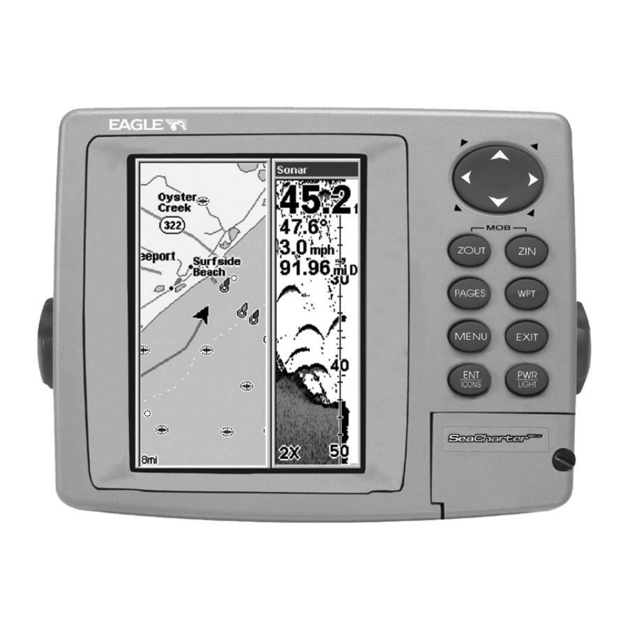
always at the top of the screen. The arrow in the center of the screen is your present position. It points in the direction you're traveling. Map Page, showing position on Bull Shoals Lake, Arkansas. At left is the full map option. At right, map with sonar option. Map Page is also the default screen that appears when you turn on the | →... - Page 55 At left, Pages Menu, showing sonar chart display option commands. At right, Sonar Page in full sonar chart display mode. Sonar chart display options (from left) split zoom and digital data.
- Page 56 Sonar Page Menu. Most of these functions are discussed in Sec. 4. Digital data overlay (depth & temperature) Fish arches Structure Sonar Page, showing full sonar chart mode. You can customize how the Sonar Page displays its pictures and other data in many ways.
-
Page 57: Basic Sonar Quick Reference
Basic Sonar Quick Reference 1. Mount the transducer, antenna and unit. Connect the unit to electric power and the transducer. (If GPS operation is desired, connect GPS antenna, too.) Make sure the MMC is in. (See complete installation de- tails beginning on page 15.) 2. -
Page 58: Sonar Operations
Sonar Operations As you can see from the quick reference on the previous page, basic operation is pretty easy, right out of the box. If you are a sonar novice, try operating the unit with the factory defaults until you get a feel for how it's working. As you're learning the basics, there is one setting you might want to tinker with from time to time —... - Page 59 You can change the sensitivity level whether you are in Auto Sensitivity mode or Manual Sensitivity mode. The adjustment method works the same in both modes, but it gives you slightly different results. Adjusting sensitivity in Auto Sensitivity Mode is similar to manually ad- justing a car's speed with the accelerator pedal while cruise control is on.
-
Page 60: Fish Symbols Vs. Full Sonar Chart
NOTE: If you want to change the sensitivity in Manual Mode, first turn off Auto Sensitivity: from the Sonar Page, press |↑ to ENSITIVITY sensitivity setting. When it's set at the desired level, press Important Tip: While you are experimenting and learning, it's possible to scramble the settings so that the sonar picture disappears from your screen. -
Page 61: Section 4: Sonar Options & Other Features
Section 4: Sonar Options & Other Features Material in this section is arranged in alphabetical order. ASP (Advanced Signal Processing) The ASP feature is a noise rejection system built into the sonar unit that constantly evaluates the effects of boat speed, water conditions and interference. -
Page 62: Alarms
3. Press ↓ or ↑ to select a setting, then press 4. To return to the previous page, press EXIT EXIT Alarms This unit has three different types of sonar alarms. The first is the Fish Alarm. It sounds when the Fish I.D. feature determines that an echo is a fish. -
Page 63: Zone Alarm
To adjust and turn on the shallow alarm: 1. Press MENU MENU 2. Press → to HALLOW 3. Press ↑ or ↓ to change the first number, then press → to move the cursor to the next number and repeat until the depth is correct, then press 4. -
Page 64: Fish Alarm
At left, Sonar Alarms menu, with Adjust Zone command selected. At right, Adjust Zone Alarm selection box, with Upper selected. 3. To set the upper boundary for the Zone Alarm, use ← or→ to select , then press ↑ or ↓ to move the top of the bar to the desired depth. PPER 4. -
Page 65: Calibrate Speed
Sonar Alarms menu with Fish Alarm selected. The check box to the left is blank, indicating the alarm is turned off. To turn the fish alarm on: 1. Press MENU MENU 2. Press ↓ to LARM 3. To turn off the alarm, press |↓... -
Page 66: Chart Speed
Chart Speed The rate that echoes scroll across the screen is called the chart speed. The default is maximum; we recommend that you leave the speed set there for virtually all fishing conditions. However, you might consider experimenting with chart speed when you are stationary or drifting very slowly. -
Page 67: Colorline
ColorLine ColorLine lets you distinguish between strong and weak echoes. It "paints" a brighter color on targets that are stronger than a preset value. This allows you to tell the difference between a hard and soft bottom. For example, a soft, muddy or weedy bottom returns a weaker signal which is shown with a narrow, colored line (dark blue tinged with red or a little yellow.) Since fish are among the weakest echoes, they show up mostly as blue arches. -
Page 68: Customize Page Displays
Thin or no ColorLine At left, little ColorLine indicates a soft bottom, probably sand or mud. At right, the wider ColorLine indicates a harder, rocky bottom. Customize Page Displays Every Page display option except Full Map and Map With Sonar has customizable data boxes to provide constant on-screen information. -
Page 69: Depth Cursor
Left; Digital Data box containing Water Temp is highlighted. Right; Data Viewer with GPS Data and Navigation categories expanded. Selecting the category name and pressing will show the category's contents, so you can choose items within it. An expanded category (one with a "–"... -
Page 70: Depth Range - Automatic
At left, Sonar Page menu with Depth Cursor command selected. At right, sonar chart with the depth cursor active. The line indicates the The cursor can be moved to any location on the screen, letting you pin- point the depth of a target. 1. -
Page 71: Depth Range - Manual
At left, Sonar Page menu with Depth Range command selected. At right, the Depth Range Control Scale. 2. The Depth Range Control Scale appears. Press ↑ or ↓ to select a dif- ferent depth range. A blue bar highlights the selected range. Range numbers in light blue cannot be selected. -
Page 72: Fish I.d. (Fish Symbols & Depths)
tions directly under the boat. This makes it useful for ice fishing, or when you're fishing at anchor. When the boat is not moving, fish sig- nals are long, drawn out lines on a normal chart display. FasTrack con- verts the graph to a vertical bar graph that, with practice, makes a use- ful addition to fishing at a stationary location. -
Page 73: Fishtrack
finding information. This and other features can help you successfully "see" beneath the boat under varied water and fishing conditions. So, practice with the unit in both the Fish I.D. mode and without to become more familiar with the feature. The default for Fish I.D. is off. Sonar Features menu with Fish I.D. -
Page 74: Frequency (Change Transducer Frequency)
Symbols with FishTrack depths Sonar Features menu with Fish I.D. Depths selected (at left, dual- frequency menu; center, single-frequency menu). When the check box to the left is checked, the feature is on. At right, Sonar Page showing Fish I.D. symbols and FishTrack depths turned on. Frequency (Change Transducer Frequency) (SeaCharter 500CDF only) The SeaCharter 500CDF transducer operates with both 200 kHz and 50... -
Page 75: Hyperscroll
Sonar Features menu with a frequency of 200 kHz selected. To change the frequency setting to 50 kHz: 1. From the Sonar Page, press 2. Press ↓ to EPTHS 3. Press EXIT EXIT To change the frequency setting to 200 kHz: 1. -
Page 76: Noise Rejection
At left, the Sonar Page menu with the Log Sonar Chart Data command selected. At right, Sonar Chart Logging menu, with the Start Logging command selected. The menu says the MMC has 34.2 MB of free space, which will record the scrolling chart for 44 minutes and 59 seconds. To record or log chart data: 1. - Page 77 The various data available from your unit are divided into categories in the Overlay Data menu. These categories include GPS Data, Naviga- tion, Trip Calculator, Time and Sonar Data. You can select items from any of these categories for display, in any combination —...
- Page 78 From Overlay Data Shown (left) press ENT to see Data Viewer (center). Select a category and press ENT. Next, select information to show on screen and press ENT to check it and turn it on (right). To remove overlaid data: 1.
- Page 79 1. Press |↓ to MENU 2. You'll see a list of the overlay data currently displayed. Select the item you want to move and press 3. The data begins to flash on your screen. Use any combination of →, ←, ↑ and ↓ to move the data to a new location on the screen. 4.
-
Page 80: Ping Speed & Hyperscroll
NOTE: Some data types can be displayed in only one font size. If that is the case, the Data Size box will not be displayed for that data type. Ping Speed & HyperScroll Ping Speed controls the rate at which the transmitter and transducer broadcast sonar sound waves —... -
Page 81: Reset Options
To change Ping Speed: 1. From the Sonar Page, press 2. The Ping Speed Control Bar appears. Press ↑ to increase ping speed; press ↓ to decrease speed. When it's set at the desired level, press To turn off HyperScroll: 1. -
Page 82: Reset Water Distance
NOTE: Reset Options does not erase any waypoints, routes, plot trails, or sonar logs. Reset Water Distance The sonar chart's Digital Data display option includes a box that shows distance traveled, called Water Distance. This information is calculated from an optional water speed sensor, not the GPS. The Water Distance window can be reset to zero using the Reset Water Distance command. -
Page 83: Sensitivity & Auto Sensitivity
NOTE: If knowing the exact depth of water beneath the keel is less important, you can calibrate the depth indicators so that they show the actual wa- ter depth from surface to bottom. To do this, first measure the distance from the face of the transducer up to the surface (the water line on the boat). -
Page 84: To Turn Auto Sensitivity Back On
can adjust sensitivity up to 100 percent but the unit will limit your minimum setting. In auto, the unit will continue to make small ad- justments, allowing for the setting you selected. In manual mode, you have complete control over sensitivity, with the ability to set it anywhere from zero to 100 percent. -
Page 85: Sonar Chart Mode (Change Chart Color Scheme)
mode, the Reset Options command will switch back to Auto and re- set the factory setting at the same time. Tip: For quicker sensitivity adjustments, try leaving the Sensitivity Control Bar on the screen as the chart scrolls. You can see the changes on the screen as you press the up or down arrows. -
Page 86: Split Zoom Sonar Chart
scales on the right side of the screen aid in determining the depth of targets. The line at the top of the screen represents the surface. The bottom depth and surface temperature (if equipped with a temperature sensor or a transducer with a temp sensor built in) show at the top left corner of the screen. -
Page 87: Digital Data
Split Zoom Sonar Chart. Image at left shows the left window zoomed to 2X. Press ZIN and the left window zooms to 4X, shown at right. Digital Data This mode shows the chart on the right side of the screen. The left side has five large digital data boxes containing (by default): Water Depth, Water Temperature, Water Speed (from an optional speed sensor), Wa- ter Distance (distance traveled or log, it also requires a speed sensor) - Page 88 At left, the Sonar Page Menu showing the Customize command high- lighted. At right, the label for the first customizable data box (Water Temp) begins flashing to indicate it is selected. 2. The Water Temperature box title bar flashes, indicating the box con- tents can be changed.
-
Page 89: Map With Sonar Split Screen
↓ to select data type| ished customizing, then press Map With Sonar Split Screen There is a page mode that splits the screen in half, with the map on the left and the sonar on the right. This screen option can be found on the Pages Menu under the Map Page category. - Page 90 At left, Main Menu with Sonar Setup command selected. Center, sub- menu with Sonar Simulator command selected. At right, Sonar Simu- lator menu, with simulator turned off (check box is unchecked). NOTE: With Simulate Position checked, the simulator will also automatically run the GPS simulator (if GPS data was recorded with the sonar log).
-
Page 91: Stop Chart
this section on Log Sonar Chart Data.) To play back your own sonar chart, make sure the MMC containing the chart is installed, then: 1. Press MENU MENU 2. Press ↓ to HART 3. Press ↓ or ↑ to select chart name| EXIT While you're in the Sonar Simulator menu, don't forget to check Simulate Position if you want to run the sonar and GPS simulators... -
Page 92: Surface Clarity
To turn on sonar and start the chart scrolling again, repeat the above step. Sonar Menu with Stop Chart command selected. The box is unchecked, indicating that the chart is scrolling across the screen. Surface Clarity The markings extending downward from the zero line on the chart are called surface clutter. -
Page 93: Zoom & Zoom Bar
2. Press ↓ or ↑ to select clarity level| EXIT EXIT EXIT Surface clutter In the illustration at left, Surface Clarity is turned off. The right view shows Surface Clarity set at High. Zoom & Zoom Bar Zooming the display is a common, fast and easy method used to enlarge small detail, fish signals and the bottom with its associated structure. -
Page 94: Zoom Pan
At left, Sonar Page, normal view. Center, same view zoomed to 2X. Right, same view zoomed to 4X Zoom Pan Your unit has the handy ability to quickly zoom in on any portion of the water column with just the touch of an arrow key. The Zoom Pan feature lets you rapidly move the zoomed area up and down to different depths. -
Page 95: Section 5: Sonar Troubleshooting
Section 5: Sonar Troubleshooting If your unit is not working, or if you need technical help, please use the following troubleshooting section before contacting the factory customer service department. It may save you the trouble of returning your unit for repair. For contact information, refer to the last page, just inside the back cover of this manual. - Page 96 3. The water may be deeper than the sonar's ability to find the bottom. If the sonar can't find the bottom signal while it's in the automatic mode, the digital sonar display will flash continuously. It may change the range to limits far greater than the water you are in. If this hap- pens, place the unit in the manual mode, then change the range to a realistic one, (for example, 0-100 feet) and increase the sensitivity.
- Page 97 To eliminate or minimize the effects of electrical noise, first try to de- termine the cause. With the boat at rest in the water, the first thing you should do is turn all electrical equipment on the boat off. Make sure the engine is also off.
- Page 98 Notes...
-
Page 99: Section 6: Basic Gps Operations
Basic GPS Operations This section addresses the unit's most basic GPS operations. The tuto- rials presented in Sec. 6 follow a chronological order. Sec. 7, Advanced GPS Operations, will discuss other more advanced functions and utili- ties. Material in Sec. 7 is arranged in alphabetical order. Before you turn on the unit and find where you are, it's a good idea to learn about the different keys, the four Page screens and how they all work together. -
Page 100: Power/Lights (Turn Unit On And Off)
3. MENU – Press this key to show the menus and submenus, which allow you to select a command or adjust a feature. This also accesses search functions for streets, intersections and highway exits. 4. ARROW KEYS – These keys are used to navigate through the menus, make menu selections, move the map cursor and sonar chart cursor and enter data. - Page 101 You can access the Main Menu from any of the four Page screens by pressing . To clear the menu screen and return to the page MENU MENU display, press EXIT Main Menu. The Main Menu commands and their functions are: Screen command: changes the contrast or brightness of the display screen.
-
Page 102: Sonar Page
Timers command: controls the up timer, down timer and alarm clock settings. Browse MMC Files command: this allows you to view the installed MMC card and the files it contains. Pages The unit has four Page displays that represent the four major operating modes. - Page 103 WARNING: Do not begin navigating with this unit until the numbers have stopped flashing! Satellite Status Page. Left view indicates unit has not locked on to any satellites and does not have a fix on its position. Right view shows satel- lite lock-on with a 3D position acquired (latitude, longitude and alti- This screen shows a graphical view of the satellites that are in view.
-
Page 104: Navigation Page
This also gives you an indicator of the fix quality the unit currently has. The smaller the position error number, the better (and more ac- curate) the fix is. If the position error flashes dashes, then the unit hasn't locked onto the satellites, and the number shown isn't valid. (For details, see the Customize Page Displays entry in Sec. - Page 105 NOTE: Remember, when the Speed, Track and Position information dis- plays are flashing, satellite lock has not been achieved and no posi- tion fix has been determined. A question mark will also flash on the present position arrow in the center of the compass rose. Speed (ground speed) is the velocity you are making over the ground.
-
Page 106: Map Page
The cross track error range is shown on the compass rose as a wide, white, corridor enclosing the course line. The outer edges of this white corridor represent lines that show the current cross track error range. The default for the cross track error range is 0.20 miles. For example, if the present position symbol touches the right cross track error line, then you are 0.20 miles to the right of the desired course. - Page 107 The arrow in the center of the screen is your present position. It points in the direction you're traveling. The magenta line extending from the back of the arrow is your plot trail, or path you've taken. The map zoom range is the distance across the screen. This number shows in the lower left corner of the screen.
-
Page 108: Background Map Vs. Mapcreate Map Content
Map Pages with high-detail MapCreate map of an urban area loaded on the MMC. At left, arterial streets are visible at the 4 mile zoom range. Center, numerous dots representing Points of Interest are visible at the 2 mile range, along with minor streets. Right, at the 0.4 mile zoom, you can see an interstate highway with an exit, major and minor streets as Background map vs. - Page 109 NOTE: Available through LEI Extras (look inside back cover for accessory ordering information), FreedomMaps are pre-made maps that con- tain all of the same information available in a custom MapCreate map. Interstate Minor Streets Marker School POI When the map is zoomed out far enough, most POIs appear as square dots.
-
Page 110: Resize Window Command
The Pages Menu also offers several map display options under the Map |← or → to Page category. To access them, press |↓ to Op- PAGES tion| EXIT Digital Data map page option. In pages that have two major windows (such as two maps) you can tog- back forth between... - Page 111 2. Four flashing arrows appear along the centerline dividing the two windows. Press an arrow key perpendicular to the centerline to adjust the window widths. Press an arrow key parallel to the centerline to switch between horizontal and vertical layout. (You can only change size, not switch layout, on the Map With Sonar page –...
-
Page 112: Basic Gps Quick Reference
Basic GPS Quick Reference Start outdoors, with a clear view of the open sky. As you practice, try navigating to a location at least a few blocks away. While you're learning, navigation in too small an area will constantly trigger arrival alarms. 1. -
Page 113: Find Your Current Position
Find Your Current Position Finding your current position is as simple as turning the unit on. Un- der clear sky conditions, the unit automatically searches for satellites and calculates its position in approximately one minute or less. NOTE: "Clear sky" means open sky, unobstructed by terrain, dense foliage or structures. -
Page 114: Selecting Any Map Item With The Cursor
Now that you've seen how the unit can find where you are, let's search for something somewhere else. Searching is one of the most powerful features in the Eagle GPS product line. In this example, we'll look for the nearest fast-food restaurant. For more information on different types of searches, refer to Sec. - Page 115 NOTE: This example requires the Point of Interest (POI) database included with a high detail MapCreate 6 custom map. After the unit has acquired a position: 1. Press |↓ to POI-R 2. You could search the entire restaurant category, but in this example we will narrow our search.
- Page 116 POI information screen on fast food restaurant nearest this position. Screen shows name, street address, phone number, latitude/longitude, distance to restaurant and its compass bearing. Figure at left shows Go To waypoint command; right figure shows Find On Map command. 6.
-
Page 117: Set A Waypoint
not have a high-detailed custom map (containing POI data) for the area you are searching loaded on the MMC, you may not find anything. Set a Waypoint A waypoint is an electronic address based on the latitude and longitude of a position on the earth. It represents a location, spot, or destination that can be stored in memory, then recalled and used later on for navi- gation purposes. -
Page 118: Create Waypoint On Map
Step 3. Sequence for setting a waypoint. Step 1: while traveling, quickly press WPT twice to call up Find Waypoint screen (seen in Step 2) and set a point. Step 3: a message says the waypoint has been saved. Step 4: ve- hicle continues on its way;... -
Page 119: Navigate To A Waypoint
change the first character, then press → to the next character and re- peat until the latitude is correct. Press 4. Press ↓ to ONGITUDE change the first character, then press → to the next character and repeat until the longitude is correct. Press previous page display. -
Page 120: Set Man Overboard (Mob) Waypoint
Course line (red) Off course range, set at 0.15 mile Navigation Page, navigating toward waypoint 001 and leaving a trail. Set Man Overboard (MOB) Waypoint One of boating's most terrifying events is having a friend or family member fall overboard. This situation can be deadly on any body of wa- ter —... -
Page 121: Navigate To Cursor Position On Map
Navigating to Man Overboard: "Man Overboard activated" message shown at left. The Navigation Page is shown in the center and Map Page is shown at right. The victim is astern of the vessel; the GPS shows which direction to steer to for the rescue. The man overboard position is also stored in the waypoint list for future reference. - Page 122 Navigate to cursor. In this example, the cursor has selected the town of 3. Press MENU cation. The Map Page will display a red line from your current position to the cur- sor position. The Navigation Page displays a compass rose showing naviga- tion information to your destination.
-
Page 123: Navigate To A Point Of Interest
Navigate to a Point of Interest For POIs that are in view on the map, you can easily use the Navigate to Cursor command above; just use the cursor to select the POI. The other method involves searching for POIs with the Find Waypoint command, launched with the lier in this section, or turn to Sec. - Page 124 Visible Active symbol symbol Sequence for saving a trail and beginning a new one. At left, My Trails command. Center, the Trails Menu. The arrow to the right of Trail 3 indicates the trail is "active," and the check to the left indicates the trail is visible on the map display.
-
Page 125: Displaying A Saved Trail
copied to your MMC for archiving or for transfer to your MapCreate software. Tip: Another quick way to stop recording one trail and begin a new one is to use the New Trail command: Press RAILS Caution: You also have the option of completely turning off trail record- ing, under the trail Options command. -
Page 126: Visual Trailing
tion during the trip, such as the time to your destination. The other two methods provide a full range of navigation data and work with both the Map Page and Navigation Page. The only difference be- tween them is "navigating a trail" follows a trail forward (from start to end) while "backtracking"... - Page 127 Figure 1. Figure 2. Figure 4. Figure 3. Navigate a trail menu sequence: Fig. 1, My Trails command. Fig. 2, Trails Menu. Fig. 3, Edit Trail Menu. Fig. 4, Edit Route Menu with Navigate Route command highlighted for Trail 1. A trail is always con- verted to a "route"...
-
Page 128: Navigate A Back Trail (Backtrack, Or Reverse)
Present position arrow Trail point Navigate trail, map views: at left driver is heading southeast straight toward trail point 3. At right, drive has reached point 3 and has turned Track or compass heading indicator Trail waypoint symbol Red course line made from trail Magenta new... -
Page 129: Transfer Custom Maps And Gps Data Files
begins showing navigation information along the trail, in reverse. NOTE: If you are already located at or near the end of your trail, the arri- val alarm will go off as soon as you hit Enter. Just press clear the alarm and proceed. 5. - Page 130 The Transfer My Data submenu asks if you want to save data to the MMC or load data from the MMC into the unit's memory. 2. The Transfer My Data menu includes a message which tells you if an MMC is present or not. If no MMC is present, you must first insert a card into the unit in order to activate the Load or Save commands.
-
Page 131: Cancel Navigation
4. Loading to unit memory: There may be more than one GPS Data File (*.USR) on the card. To select a file, press to activate the selec- tion box, use ↓ or ↑ to highlight the file, then press to accept the selection. - Page 132 Notes...
-
Page 133: Section 7: Advanced Gps Operations
Advanced GPS Operations Find Distance From Current Position To Another Location 1. While on the Map Page press: 2. Center your cursor over the position you want to find the distance to. A rubber band line appears, connecting your current position to the cursor's location. -
Page 134: Icons
Icons Icons are graphic symbols used to mark some location, personal point of interest or event. They can be placed on the map screen, saved and re- called later for navigation purposes. These are sometimes referred to as event marker icons. This unit has 42 different symbols you can pick from when creating an icon. -
Page 135: Delete An Icon
Delete an Icon You can delete all the icons at one time, you can delete all icons repre- sented by a particular symbol, or you can use the cursor to delete a se- lected icon from the map. 1. Press |↓... -
Page 136: Routes
Routes A route is a series of waypoints, linked together in an ordered sequence, that's used to mark a course of travel. You can visualize a route as a string of beads: The beads represent waypoints and the string repre- sents the course of travel connecting waypoint to waypoint. - Page 137 Route Planning command on Main Menu, left, will open the Route List screen, right. 2. If necessary, press ↑ to select , then press . (To add to OUTE an existing route, press ↓ or ↑ to route name| 3. Press ↓ to |↓...
- Page 138 Route creation sequence, from left: Fig. 1. Set route waypoint (1) at the cove entrance. Fig. 2. Move cursor northeast to set point (2) at channel entrance. Fig. 3. With point (2) set, move cursor southeast to mark channel exit with waypoint (3). In figures 2 and 3, notice the rubber band line extending from the previously set waypoint to the cursor.
-
Page 139: Delete A Route
8. To save your route, press screen, with the route automatically named "Route 1" and stored in the unit's internal memory. You can edit the route and run other commands, but if you are finished with the route for now, return to the last page displayed by pressing EXIT EXIT... -
Page 140: Navigate A Route
3. Use ↓ and ↑ to select a command from the Edit Route Waypoints menu and press route by clicking on a map location with the cursor. Add Waypoint calls up the Waypoint List so you can insert a waypoint from the list. Re- move Waypoint will delete the waypoint from the route. -
Page 141: Navigate A Route In Reverse
2. Press ↓ to select route name| 3. Upon arrival at your destination, cancel navigation: press |↓ to MENU MENU The following figures show what the Navigation Page and Map Page look like while navigating a route. Navigate a Route in Reverse Here's how you run a route backward, from the end waypoint to the beginning waypoint: 1. -
Page 142: Trails
Figure 3. In Fig. 3 the traveler has turned northeast on his new course and is heading straight for Wpt 2, which is 0.27 miles away. Fig. 4 shows route navigation on the Map Page. In this figure, the traveler has reached Wpt 2 and is starting on the leg between Wpts 2 and 3. -
Page 143: Edit A Trail Color
At left, trail selected with map cursor. The box at the bottom of the screen shows distance and bearing from current position to the se- lected point on the trail. At right, the Edit Trail menu. Edit a Trail Color To edit a trail color: press name| |↓... -
Page 144: Utilities
Utilities Utilities are useful tools for traveling or for outdoor activities. Alarm Clock To get to the alarm clock menu: press LARM LOCK Sun/Moon Rise & Set Calculator To get to the Sun/Moon menu: press ALCULATIONS Trip Calculator To get to the Calculator menu: press LATOR Trip Down Timer To get to the Down Timer menu: press... -
Page 145: Edit A Waypoint (Name, Symbol, Position)
Edit a Waypoint Waypoint Name To edit waypoint name: 1. Press |↑ to waypoint from the list by using ↑ or ↓ to select first character then press → to choose the next character. After the desired waypoint is highlighted in the list, press screen. -
Page 146: Set A Waypoint By Average Position
Set a Waypoint by Average Position This feature sets a waypoint at the current position after taking several position readings and averaging them. This boosts waypoint position accuracy by helping to eliminate errors caused by atmospheric condi- tions and other factors. 1. -
Page 147: Section 8: System & Gps Setup Options
Section 8: System & GPS Setup Options Alarms This unit has several GPS alarms. The factory default setting has all of these but the anchor alarm turned on. You can turn the alarms off and on and change their distance settings. You can set an arrival alarm to flash a warning message and sound a tone when you cross a preset distance from a waypoint. -
Page 148: Check Mmc Files And Storage Space
3. To change distance settings, scroll gory, then press → | ↓ to change the first character, then press → to the next character and repeat until the name is correct. 4. When your adjustments are finished, return to the last page dis- played by repeatedly pressing IMPORTANT ALARM NOTES: Anchor Alarm - The anchor alarm may be triggered even when... -
Page 149: Configure Nmea
Menus for changing Com Port settings. For assistance in configuring the unit to communicate with another device, consult the factory; customer service phone numbers are in the back of this manual. Also see the entry below for Configure NMEA. To set Com Port Configuration: 1. -
Page 150: Coordinate System Selection
• GSA and GSV transmits fix mode, DOP values, and satellites in view information. • DBT transmits the depth below the transducer. • DPT transmits the depth • MTW transmits the water temperature. • VLW transmits the distance traveled through water as meas- ured by the paddle wheel. -
Page 151: To Setup Loran Td
New Zealand, Swedish, Swiss, Taiwan and Greek grid systems. UTM's are marked on USGS topographic charts. This system divides the Earth into 60 zones, each 6 degrees wide in longitude. British, Irish, Finnish, German, New Zealand, Swedish, Swiss, Taiwan, and Greek grid systems are the national coordinate system used only in their respective countries. -
Page 152: Map Fix
Map Fix Map Fix is used with charts or maps. This system asks for a reference position in latitude/longitude, which you take from a marked location on the map. It then shows the present position as distance on the map from that reference point. -
Page 153: Customize Page Displays
Press → to ELECT Select the waypoint (or a landmark of POI) that you saved the reference point under and press screen with the command returns to the Configure Map Fix menu. Finally, press menu. Now press ↑ to press EXIT EXIT distance from the reference point you chose. -
Page 154: Simulating Trail Or Route Navigation
To get to the GPS Simulator: 1. Press MENU MENU 2. Press ↓ to GPS S IMULATOR GPS Setup Menu, left; GPS Simulator menu, center. Map Page showing Track and Speed steering arrow indicators, right. In this example, you are "traveling" across Mudisland Point on a track of 19º... -
Page 155: Hide Gps Features
3. Begin navigating along the trail/route. (If you are close enough to the first waypoint, the arrival alarm will usually go off as soon as naviga- tion begins. Press press ↑ to increase speed to the desired setting. 4. Press to turn off the steering and speed boxes. -
Page 156: Map Data
works in conjunction with the navigation features. First, start navigation to a waypoint. (See the waypoint section for more information on navigating to a waypoint.) Then, with the auto zoom mode on, the unit zooms out until the entire course shows, from the present position to the destination waypoint. -
Page 157: Map Boundaries
. With the option highlighted, press NFORMATION on) and uncheck it (turn off.) After the option is set, press return to the page display. Map Boundaries From the Map Page, press . With the option highlighted, press OUNDARIES on) and uncheck it (turn off.) After the option is set, press return to the page display. -
Page 158: Map Datum Selection
Map Datum Selection Maps and charts are based on a survey of the area that's covered by the map or chart. These surveys are called Datums. Maps that are created using different datums will show the same latitude/longitude in slightly different locations. -
Page 159: Map Orientation
or ← to select a subcate- ↑ ↓ → 2. Press to select a category or press gory. Press to turn it off (no check) or on (checked.) 3. To return to the last page displayed, press EXIT EXIT Map Menu, left, Map Categories Drawn Menu, right. Map Orientation By default, this receiver shows the map with north always at the top of the screen. -
Page 160: Navionics Charts
To correct this problem, a track-up mode rotates the map as you turn. Thus, what you see on the left side of the screen should always be to your left, and so on. Another option is course-up mode, which keeps the map at the same orientation as the initial bearing to the waypoint. -
Page 161: Port Information
. Use ↑ or ↓ to select the Map Name, then press HOICE EXIT EXIT These figures show menu sequence (from left to right) for selecting a 3. To turn off a Navionics chart, From the Map Page, press |↓ to then press EXIT Port Information... -
Page 162: Tidal Current Information
Port Services icons Pop-up name box Navionics chart showing Port Services icon selected by cursor. 3. To scroll through the Service Categories window: press ↑ or ↓ to see the types of services available. As you highlight a different category, the list in the lower window changes. To return to the Map Page, press EXIT EXIT... - Page 163 Station location. An example is displayed above. When you zoom in to a sufficiently small zoom range, the icon itself be- comes an animated arrow showing tidal current velocity and direction for the selected tidal station at the present time. At larger zoom ranges, you can select the boxed "C"...
-
Page 164: Tide Information
the screen is an approximate view of the flood and ebb pattern for the day, from midnight (MN), to noon (NN) to midnight (MN). The velocity scale at the top left side of the graph changes dynamically based upon the maximum velocity of the current for that day. Slack water, the period of little or no current, is represented by the Slack Water Line (SWL). - Page 165 Pop-up name box Navionics chart showing Tide Station icon selected by cursor. In the example above, the tide is at 1.5 feet and rising, as shown by the up arrow at the top of the icon. The Tide Information screen displays daily tidal data for this station on this date at the present time.
-
Page 166: Pop-Up Help
2. Use ↑ and ↓ to select the desired month, day or year, then press To clear the information screen, press Pop-up Help Help is available for virtually all of the menu labels on this unit. By highlighting a menu item and leaving it highlighted for a few seconds, a "pop-up"... -
Page 167: Require Waas
System Menu with Reset Options command selected. Require WAAS You can force the unit to require WAAS for reporting a valid position. (The default setting, off, uses WAAS automatically, but doesn't require it to yield a position.) Here's how to turn it on and off: 1. -
Page 168: Set Language
maximum contrast. Screen Command, left, and Screen Menu with Contrast bar selected, right. To adjust the display's brightness: Press ↓ to RIGHTNESS scale is minimum contrast; the right end is maximum contrast. To adjust the screen's display mode: Press ↓ to ISPLAY Set Language This unit's menus are available in 10 languages: English, French, Ger-... -
Page 169: Set Local Time
3. Use ↓ or ↑ to select a different language and press now appear in the language you selected. Set Local Time Using the correct local time setting is handy when estimating local ar- rival time while navigating. Also, the time and date are saved when a waypoint is created. -
Page 170: Software Version Information
Software Version Information From time to time, Eagle updates the operating system software in some of its products. These software upgrades are usually offered to customers as free downloads from our web site, www.Eagle.com. These upgrades make the unit perform better or introduce a new feature or function. -
Page 171: Track Smoothing
Sounds command, left. At right, the Sounds menu. Once in the Sounds menu: To set Key Press Sounds: With the option highlighted, press check it (turn on) and uncheck it (turn off.) After the option is set, press to return to the page display. EXIT EXIT To set Alarm Sounds: Press ↓... -
Page 172: Trail Options
Track Smoothing option, turned on. Trail Options There are several options you can use with trails. Some affect all trails, other options can be applied to a particular trail. You can change the way trails are updated, display or hide trails, create a new trail, delete a trail, etc. - Page 173 WARNING: If you uncheck the Update Trail option, automatic trail creation and recording will be turned off. You must turn it back on to record trails. The default setting is on. From the Trails Menu, press ↓ to highlighted, press Update Trail Criteria (Auto, Time, Distance) The options are automatic, time, or distance.
-
Page 174: Delete Trail
Specific Trail Options Delete Trail To delete a specific trail: From the Trails Menu, press ↓ to Trail Name| . The Edit Trail menu appears as seen in the following fig- ure. Press ↓ to |← to ELETE RAIL Edit Trail menu. New Trail To manually start a new trail, in the Trails Menu, make sure RAIL... -
Page 175: Units Of Measure
Main Menu with Transparency command selected. To adjust Menu Transparency level: Press |↓ to . The slider bar MENU MENU RANSPARENCY RANSPARENCY appears. Press ↑ or ↓ to move the bar. The lower end of the scale makes the menus opaque; the upper end is maximum transparency. Units of Measure This menu sets the speed and distance (statute or nautical miles, me- ters), depth (feet, fathoms, or meters), temperature (degrees Fahrenheit... - Page 176 Notes...
-
Page 177: Section 9: Searching
NOTE: The background map loaded in your unit lets you search for U.S. Interstate Highway exits and exit services, as well as some land features, including cities and lakes. For a full set of searchable land features, including landmarks, streets, addresses and Points of In- terest, you must load your own high-detail custom map produced with our MapCreate 6 software. -
Page 178: Find Addresses
In search results, the distance and bearing to the selected item will be calculated from the current position. In the case of a cursor search, the search results show distance and bearing from the cursor, but an indi- vidual waypoint's information screen shows distance and bearing from Address search result list, left. - Page 179 Find Address menu, left; Find Street menu, center, with Find By Name field active; street name entry complete, right. 5. To enter a city name, press ↓ to want to find addresses within a particular city. This option is designed so you can limit an address search to a single city if necessary (see the following note).
- Page 180 6. When the necessary search fields are filled in, press ↓ to . Your unit asks you to wait while it searches for the address. DRESS (If an address is not in the database, a message appears saying the ad- dress could not be found.) 7.
-
Page 181: Find Any Item Selected By Map Cursor
Left, Map Page showing location of the address on the map, high- lighted by cursor. Center, this address is a business in the POI data- base, so you can display the POI information window, then navigate to it. At right, this address is not in the POI database, so the Waypoint key will not display any information for this address. - Page 182 Find Highway Exits command, left, and Find Exit menu, right. 2. First, select a highway name by pressing , which calls up the Find By Name menu. There are two highway search options: A. You can spell out the highway name in the top selection box. Press ↑ or ↓ to change the first letter, then press →...
- Page 183 Find Exit menu, with an exit selected in the list. 4. In the Exit Information screen you have two choices. A. Press to navigate or go to the exit. B. Press exit on the map. Go To Exit option, left, Find On Map option, right. Tip: You can also look up some additional information on the Exit Serv- ices located near this exit.
-
Page 184: Find Map Places Or Points Of Interest (Poi)
Exit Information screen, left; general location and amenities information, at right. Find Map Places or Points of Interest (POI) ↓ ↑ 1. Press , press to select a map place or POI category, then . (To narrow your search, press → or ← to select a subcate- press gory before pressing .) You will be given two options;... - Page 185 Find by Nearest option, left, Calculating screen, center, POI list, right. 3. Search by name of POI. Press . There are two options: A. You can spell out the POI in the top selection box. Press ↑ or ↓ to change the first letter, then press →...
-
Page 186: Find Streets Or Intersections
Go To POI option, left, Find on Map POI option, right. Find Streets or Intersections Find a Street 1. From the Map Page, press |↓ to and the Find MENU TREETS Streets Menu appears. Find Streets command, left, Find Streets menu, right. 2. - Page 187 Find Street By Name menu. Spell out name in the top box, or select from the list in the lower box. 3. The Find Streets menu reappears with the street you're searching for in the First Street box. (In this example, it's I-35.) To search for that street, press ↓...
- Page 188 Map Page showing results of a street search. The cursor points to the located street. If you want to navigate to the found street at the cursor location, just press MENU EXIT Find an Intersection You must enter one street in the First Street dialog box and enter the next street in the Second Street dialog box.
- Page 189 street. You could now use similar techniques to select a city or Zip code, but your search will probably be faster if you leave those boxes blank. (You can specify a city and/or Zip code later on to narrow the search, if the resulting list is too long.) Find Intersection command highlighted, left.
-
Page 190: Find Waypoints
Find Waypoints 1. Press |↑ to AYPOINTS 2. If searching for the Nearest waypoint press . If searching by Name press ↓ to . (To search by name, jump to step 5.) |ENT Find Waypoint menu, left; Find By Nearest command, center, Find by Name command, right. - Page 191 command is already highlighted.) The unit will show navigation in- formation to the waypoint. B. To find the waypoint, press → to Page appears with the cursor highlighting the found waypoint. Waypoint Information screens with the Go To Waypoint command se- lected, left, and the Find on Map command selected, right.
- Page 192 Find By Name menu, left. Waypoint Information screen, center. At right, the found waypoint is highlighted by the cursor on the Map Page. A. To navigate to the waypoint, press . (Go To Waypoint com- mand is already highlighted.) The unit will show navigation infor- mation to the waypoint.
-
Page 193: Section 10: Supplemental Material Datums Used By This Unit
Section 10: Supplemental Material Datums Used by This Unit WGS 1984 Default Adindan Mean for Ethiopia, Sudan Adindan Burkina Faso Adindan Cameroon Adindan Ethiopia Adindan Mali Adindan Senegal Adindan Sudan Afgooye Somalia Ain el Abd 1970 Bahrain Ain el Abd 1970 Saudi Arabia Anna 1 Astro 1965 Cocos Islands... - Page 194 Chua Astro Paraguay Corrego Alegre Brazil Dabola Guinea Djakarta (Batavia) Indonesia (Sumatra) DOS 1968 New Georgia Islands (Gizo Island) Easter Island 1967 Easter Island European 1950 Mean for Austria, Belgium, Denmark, Finland, France, West Germany, Gi- braltar, Greece, Italy, Luxembourg, Neth- erlands, Norway, Portugal, Spain, Sweden, Switzerland...
- Page 195 Naparima BWI Trinidad & Tobago North American 1927 Mean for Antigua, Barbados, Barbuda, Caicos Islands, Cuba, Dominican Republic, Grand Cayman, Jamaica, Turks Islands North American 1927 Mean for Belize, Costa Rica, El Sal- vador, Guatemala, Honduras, Nicaragua North American 1927 Mean for Canada North American 1927 Mean for CONUS...
- Page 196 Point 58 Sweden Santo (DOS) 1965 Espirito Santo Island Sao Braz Azores (Sao Miguel, Santa Maria Islands) Sapper Hill 1943 East Falkland Island Schwarzeck Nambia Selvagem Grande Salvage Islands SGS 85 Soviet Geodetic System 1985 South American 1969 Mean for Argentina, Bolivia, Brazil, Chile, Colombia, Ecuador, Guyana, Paraguay,...
-
Page 197: Fcc Compliance
This device complies with Part 15 of the U.S. Federal Communi- cations Commission (FCC) Rules. Operation is subject to the fol- lowing two conditions: (1) this device may not cause harmful in- terference, and (2) this device must accept any interference re- ceived, including interference that may cause undesired opera- tion. - Page 198 Notes...
- Page 199 THIS IS A LEGAL AGREEMENT BETWEEN THE END-USER WHO FIRST PURCHASES THIS PRODUCT AS A CONSUMER ITEM FOR PERSONAL, FAMILY, OR HOUSEHOLD USE ("YOU") AND EAGLE ELECTRONICS, INC., THE MANUFACTURER OF THIS PRODUCT ("WE", "OUR", OR "US"). USING THE PRODUCT ACCOMPANIED BY THIS LICENSE AGREEMENT CONSTITUTES ACCEPTANCE OF THESE TERMS AND CONDITIONS.
- Page 200 DATABASES LIMITED WARRANTY "We", "our", or "us" refers to Eagle Electronics, Inc., the manufacturer of this product. "You" or "your" refers to the first person who purchases the product as a consumer item for personal, family, or household use. The Databases Limited Warranty applies to the one or more databases that your product may contain.
- Page 201 EAGLE ELECTRONICS FULL ONE-YEAR WARRANTY "We," "our," or "us" refers to EAGLE ELECTRONICS, INC., the manufacturer of this product. "You" or "your" refers to the first person who purchases this product as a con- sumer item for personal, family or household use.
-
Page 202: How To Obtain Service
…in the USA: We back your investment in quality products with quick, expert service and genuine Eagle parts. If you're in the United States and you have technical, return or repair questions, please contact the Factory Cus- tomer Service Department. Before any product can be returned, you must call customer service to determine if a return is necessary. -
Page 203: Accessory Ordering Information For All Countries
5. Write the Return Authorization (RA) number on the outside of the box underneath your return address. 6. For your security, you may want to insure the package through your shipping courier. Eagle does not assume responsibility for goods lost or damaged in transit. -
Page 204: Visit Our Website
Visit our web site: www.eaglesonar.com Eagle Pub. 988-0156-041 © Copyright 2004 All Rights Reserved Printed in USA 121004 LEI-Eagle...
Need help?
Do you have a question about the 500C and is the answer not in the manual?
Questions and answers