
Related Manuals for Eagle FishEasy 250 DS


Summary of Contents for Eagle FishEasy 250 DS
- Page 1 Pub. 988-0151-421 www.eaglesonar.com FishEasy 250 DS ® & SeaFinder 250 DF ® Fish-Finding & Depth-Sounding Sonars Installation and Operation Instructions...
- Page 2 250 & Seafinder ® Eagle Electronics may find it necessary to change or end our policies, regulations, and special offers at any time. We reserve the right to do so without notice. All features and specifications subject to change without notice.
-
Page 3: Table Of Contents
Section 1: Introduction...1 Specifications: FishEasy 250 DS & SeaFinder 250 DF ...1 How Sonar Works...3 Preparations ...4 Section 2: Installation & Accessories...7 Recommended Tools and Supplies ...7 Selecting a Transducer Location ...8 How low should you go? ...9 Shoot-thru-hull vs. Transom Mounting ...10 Transom Transducer Assembly and Mounting ...11 Trolling Motor Bracket Installation...15 Transducer Orientation and Fish Arches...16... - Page 4 FishTrack™ ...46 Alarms...47 Fish Alarm ...47 Depth Alarms ...47 Shallow Alarm ...48 Deep Alarm...49 Battery Alarm...49 Noise Rejection and ASP ...50 Depth Display...52 Temperature Display ...52 Voltage ...54 Units...54 Backlight...54 Contrast ...55 Simulator ...55 Set Language ...56 Software Information...56 Reset Options...57 Troubleshooting...59...
-
Page 5: Section 1: Introduction
– right out of the box. All you have to do is press the on ( To get started with your Eagle sonar, first read the installation section. It contains instructions for mounting the sonar unit, the transducer and any optional accessories, such as a speed sensor. - Page 6 Back-up memory:...Built-in memory stores sonar settings when Languages: ...11 International languages. Frequency: ...83/200 kHz for FishEasy 250 DS; 50/200 kHz Transducers:...FishEasy 250 DS: a compact Dual-Search Watts: ...SeaFinder 250 DS: 2,400 watts peak-to-peak; Depth capability: ...SeaFinder 250 DS: 1,300 feet (396 meters) Depth display: ...Continuous display.
-
Page 7: How Sonar Works
Sonar has been around since the 1940s, so if you already know how it works, skip ahead to the next segment. But, if you have never owned a sonar fish finder, this segment will explain the under water basics. Sonar is an abbreviation for SOund NAvigation and Ranging, a tech- nology developed during World War II for tracking enemy submarines. -
Page 8: Preparations
Dual Search & Dual Frequency The FishEasy 250 DS is packed with a Dual Search Skimmer Trans- ducer that can transmit at 83 kHz and 200 kHz. The SeaFinder 250 DF has a dual frequency transducer that transmits at 50kHz and 200kHz. - Page 9 This will help you make sure you have enough cable length for the de- sired configuration. 2. Determine the approximate location for the transducer and its cable route. 3. Determine the location of your battery or other power connection, along with the power cable route. 4.
- Page 10 Notes...
-
Page 11: Section 2: Installation & Accessories
Section 2: Installation & Accessories These instructions will help you install your Skimmer transducer on a transom, on a trolling motor or inside a hull. Please read all instruc- tions before proceeding with any installation. Your Skimmer transducer typically comes packaged with a one-piece stainless steel bracket for mounting it to the transom of your boat. -
Page 12: Selecting A Transducer Location
Shoot-through hull installations Tools: these will vary depending on your hull's composition. Consult your boat dealer or manufacturer. Supplies: 100 grit sandpaper, good quality epoxy adhesive. Selecting a Transducer Location 1. The transducer must be placed in a location that has a smooth flow of water at all times. -
Page 13: How Low Should You Go
CAUTION: Clamp the trans- ducer cable to transom near the transducer. This will help prevent the transducer from entering the boat if it is knocked off at high speed. Good location Poor angle Good and poor transducer locations. How low should you go? For most situations, you should install your Skimmer transducer so that its centerline is level with the bottom of the boat hull. -
Page 14: Shoot-Thru-Hull Vs. Transom Mounting
transducer up or down. If you frequently lose bottom signal lock while running at high speed, the transducer may be coming out of the water as you cross waves or wakes. Move the transducer a little lower to help prevent this. If you cruise or fish around lots of structure and cover, your transducer may be frequently kicking up from object strikes. -
Page 15: Transom Transducer Assembly And Mounting
Third, a transducer CAN NOT shoot through wood and metal hulls. Those hulls require either a transom mount or a thru-hull installation. Fourth, if your Skimmer transducer has a built in temp sensor, it will only show the temperature of the bilge, not the water surface temp. Follow the testing procedures listed in the shoot-thru-hull installation section at the end of this instruction booklet to determine if you can satisfactorily shoot through the hull. - Page 16 If the transducer's face isn't parallel with the ground, remove the transducer and ratchets from the bracket. Place the ratchets into the holes in the bracket with the letter "B" aligned with the dot stamped in the bracket. Reassemble the transducer and bracket and place them against the transom.
- Page 17 Assemble transducer and bracket. 4. Drilling mounting holes. Hold the transducer and bracket assembly against the transom. The transducer should be roughly parallel to the ground. The transducer's centerline should be in line with the bottom of the hull. Don't let the bracket extend below the hull! Mark the center of each slot for the mounting screw pilot holes.
- Page 18 Route cable over bolt and through bracket. Side view (left) and shown from above (right). Attach the transducer to the transom. Slide the transducer up or down until it's aligned properly with the bottom of the hull as shown in the preceding and following figures. Tighten the bracket's mount- ing screws, sealing them with the sealant compound.
-
Page 19: Trolling Motor Bracket Installation
Electrical noise from the engine's wiring, bilge pumps, VHF radio wires and cables, and aerators can be picked up by the sonar. Use caution when routing the transducer cable around these wires. WARNING: Clamp the transducer cable to the transom close to the transducer. -
Page 20: Transducer Orientation And Fish Arches
2. Slide the adjustable strap supplied with the TMB-S through the slot in the transducer bracket and wrap it around the trolling motor. Po- sition the transducer to aim straight down when the motor is in the water. Tighten the strap securely. 3. - Page 21 Transducer aimed too far back Full fish arch Transducer angles and their effects on fish arches. If the arch slopes up – but not back down – then the front of the trans- ducer is too high and needs to be lowered. If only the back half of the arch is printed, then the nose of the transducer is angled too far down and needs to be raised.
-
Page 22: Shoot-Thru-Hull Preparation
Shoot-Thru-Hull Preparation Hulls With Flotation Materials The transducer installation inside a fiberglass hull must be in an area that does not have air bubbles in the resin or separated fiberglass lay- ers. The sonar signal must pass through solid fiberglass. A successful transducer installation can be made on hulls with flotation materials (such as plywood, balsa wood or foam) between layers of fiberglass if the material is removed from the chosen area. - Page 23 To choose the proper location for shoot-thru-hull mounting, follow these testing procedures. You may need a helper to complete these steps. 1. Anchor the boat in about 30 feet of water. Add a little water to the sump of the boat. Plug the transducer into the sonar unit, turn it on, then hold the transducer over the side of the boat in the water.
- Page 24 3. Now move the transducer around to find the best location with the strongest possible bottom signal. If you find a spot with an acceptable bottom signal, mark the location and move on to step 4. If you can not get an acceptable bottom signal, try turning up the sensi- tivity by three or five keystrokes and then move the transducer around once more.
-
Page 25: Shoot-Thru-Hull Installation
Shoot-thru-hull Installation 1. Make sure the area is clean, dry and free of oil or grease, then sand both the inside surface of the hull and the face of the transducer with 100 grit sandpaper. The sanded hull area should be about 1-1/2 times the diameter of the transducer. -
Page 26: Power And Cable Connections
Thoroughly stir the two compounds together until the mixture has a uniform color and consistency. Do not mix too fast or bubbles will form in the epoxy. After mixing, you have 20 minutes to complete the in- stallation before the epoxy becomes unworkable. Spread a thin layer of epoxy (about 1/16"... - Page 27 In saltwater environments we recommend you connect the power cable to the auxiliary power switch included in most boat designs. If that results in electrical interference, or if such a switch is not available, we recommend connecting direct to the battery and in- stalling an inline switch.
-
Page 28: Mounting The Sonar Unit: In-Dash Or Bracket
If possible, keep the power cable away from other boat wiring, espe- cially the engine's wires. This will provide the best isolation from elec- trical noise. If the cable is not long enough, splice #18 gauge wire onto The power cable has two wires, red and black. Red is the positive lead, black is negative or ground. -
Page 29: Bracket Installation
In-dash mounting template for FishEasy 250DS, showing dimensions. The preceding figure is not printed to scale. A scaled template is avail- able for free download from our web site, www.eaglesonar.com. Bracket Installation Mount the unit in any convenient location, provided there is clearance when it’s tilted for the best viewing angle. - Page 30 173.9 [6.85] 137.9 [5.43] Millimeter [Inch] Front view (left) and side view (right) showing dimensions of sonar Drill a 5/8" (15.9 mm) hole in the dash for the power/transducer cable. The best location for this hole is immediately under the gimbal bracket location.
-
Page 31: Portable Installation
Tilt the unit to the desired viewing angle and tighten the knobs finger tight. Portable Installation Like many Eagle products, this sonar unit is capable of portable opera- tion by using an optional portable power pack. The power pack and an optional portable transducer expand the uses of your sonar unit. The... -
Page 32: Portable Transducer Assembly
alkaline batteries or an optional sealed, rechargeable battery. For set- up directions, refer to the pack's instruction sheet. "D" cell battery Install batteries in power case battery adapter. Portable Transducer Assembly Recommended tools for installation include a slotted screw driver and two adjustable wrenches. - Page 33 Screw the suction cup onto the bracket using the supplied screw and flat washer. Tie the nylon cord through the hole in the top of the bracket. When using this transducer, tie the other end of the nylon cord to the boat. This will help prevent the loss of the transducer if it comes off the boat.
- Page 34 Moisten the cup, then press it onto the hull as firmly as possible. Tie the nylon cord to the boat and route the transducer cable to the sonar unit. Your portable sonar is now ready for use. NOTE: For optimum operation, the portable transducer should be adjusted so that it is parallel to the ground.
-
Page 35: Section 2: Operation
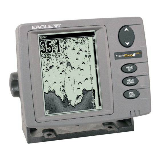
Keyboard Basics The unit sounds a tone when you press any key. Numbers in the figure correspond to key explanations below: Eagle FishEasy 250 DS. 1. PWR/CLEAR In this manual, the Power/Clear key is referred to as . Press this key to turn the unit on and off. -
Page 36: Memory
2. MENU UP & MENU DOWN These keys appear in the manual text as Most of the time, you can press either of the menu keys, so in those cases, the text uses the word you can press the MENU UP key cycles forward through the menus. -
Page 37: Display
The Backlight menu with backlight turned on. Display The lights will flash for about 10 seconds when the unit is turned on. The backlight menu will appear on the screen. Use to turn the ↑ ↓ backlight on or off. Press to clear the menu from the screen. -
Page 38: Full Chart
Digital depth Water Temp Bottom signal Depth range at bottom of depth scale Full Chart The unit's default page, Full Chart shows all echoes scrolling across the full screen. The bottom signal scrolls across the screen from right to left. The line at the top of the screen represents the surface. The bottom depth —... -
Page 39: Fastrack
Digital depth Water Temp Bait fish Bottom signal Depth range at bottom of depth scale Full Chart page showing digital depth (above) and temp (below). The Fish I.D. feature is turned off. FasTrack This feature automatically converts echoes to short horizontal lines on the display's far right side. -
Page 40: Depth Range
FasTrack gives you a rapid update of conditions directly under the boat, making it useful for ice fishing or when fishing at anchor. When the boat is not moving, fish signals are long, drawn out lines on a nor- mal display. FasTrack converts the graph to a vertical bar graph that makes a useful addition to fishing at a stationary location. -
Page 41: Zoom
Zoom The zoom feature enlarges all images on the screen by doubling (2X) or quadrupling (4X) the size of the echoes. When you activate the zoom command, the screen will be split in half with the zoomed area dis- played on the left. The normal view will be shown on the right side of the screen. -
Page 42: Sensitivity
To do this, make sure Depth Range is set to manual mode. Next, re- peatedly press MENU , then press MENU UP Use ↑ ↓ to select a desired zoom range. When you are finished, press to clear the menu from the display. Enlarged fish arches... - Page 43 Sensitivity set to manual mode (left). Sensitivity scroll bar (right). You can change the sensitivity level whether you are in Auto Sensitivity mode or Manual Sensitivity mode. The adjustment method works the same in both modes, but provides slightly different results. To adjust sensitivity in Auto Mode: Repeatedly press until the...
-
Page 44: Grayline
Bait school Fig. 1 Fig. 3 These figures show results of different sensitivity levels on the same location. Fig. 1: Sensitivity at 85 percent, determined by Auto Sensitiv- ity. Typical of full auto mode. Fig. 2: Sensitivity set at 71 percent. Fig. 3: Sensitivity set at 47 percent. - Page 45 If you have two signals of equal size, one with gray and the other with- out, then the target with gray is the stronger signal. This helps distin- guish weeds from trees and fish from structure. Thin or no Grayline A small amount of Grayline indicates a soft bottom (left), probably sand or mud.
-
Page 46: Chart Speed
The default level of Grayline is usually adequate for most conditions. Experiment with the unit to find the Grayline setting best for you. To change the Grayline level, repeatedly press until the MENU RAYLINE scroll bar appears. Press to increase Grayline, to decrease it. -
Page 47: Frequency
100% Frequency The FishEasy 250 DS has a Dual Search transducer that can transmit signals at 83 kHz and 200 kHz. The SeaFinder 250 DF is packed with a Dual Frequency transducer that transmits at 50 kHz and 200 kHz. -
Page 48: Fish I.d
FishEasy 250 dual search frequency menu (left). SeaFinder 250 dual frequency menu (right). To switch the Frequency, repeatedly press until the Frequency MENU menu appears. Press ↑ or ↓ to select the desired frequency. Press clear the frequency menu from the screen. Fish I.D.... - Page 49 Your sonar unit's microcomputer is sophisticated, but it can be fooled. It can not distinguish between fish and other suspended objects such as trotlines, turtles, submerged floats, air bubbles, etc. Individual tree limbs extending outward from a group of limbs are the hardest objects for the Fish I.D.
-
Page 50: Fishtrack
Then, you can turn on Fish I.D. and the audible fish alarm. When that lunker swims under your boat, you will hear it! Fish I.D. can also be useful when you want to screen out some of the so- nar detail gathered by your unit. For example, it can help cut through the clutter of suspended bubbles caused by wave action or boat wakes. -
Page 51: Alarms
Alarms Your sonar unit has four alarms: fish, shallow, deep and battery. NOTE: If one of the alarms goes off, press remain silent until it is triggered again. Fish Alarm The Fish Alarm sounds a tone when a fish symbol appears on the screen. -
Page 52: Shallow Alarm
vessel enters water that is more shallow than the alarm's setting. The deep alarm sounds a tone your vessel enters water that is deeper than the alarm's setting. Shallow Alarm To set the shallow alarm depth, repeatedly press until MENU HALLOW appears. -
Page 53: Deep Alarm
To turn off the alarm, repeatedly press menu appears. Press Deep Alarm To set the deep alarm depth, repeatedly press appears. Deep Alarm menu (left). Deep Alarm dialog box (right). Press the ↓ to enter the first number in the dialog box, then press ↓... -
Page 54: Noise Rejection And Asp
Battery Alarm menu (left). Low Battery Alarm Value (right). Press the ↓ appear. Input a voltage value between 7 and 18 volts. Use the to enter the first number in the dialog box, then press move to the next digit. Repeat those steps until the desired value has been entered in the dialog box. - Page 55 over the face of the transducer and even vibration from the engine. In all cases, noise can produce unwanted marks on the display. Noise Rejection menu. The ASP noise rejection feature is especially useful because, typically, it lets you operate the boat at all speeds without adjusting the sensi- tivity or other controls.
-
Page 56: Depth Display
Depth Display Depth may be displayed on the screen in a small, medium or large size or can be turned off completely. To display Depth: Repeatedly press until the menu appears. Use to select ↑ ↓ MENU EPTH the size of the depth display. Press to clear the menu. - Page 57 Temperature menu (left). Temperature display set to small size (right). To display Temperature: Repeatedly press until the menu appears. Use ↑ ↓ MENU EMPERATURE select the size of the temperature display. Press to clear the menu. Voltage menu with the voltage display turned off (left) and with volt- age set to a small display size (right).
-
Page 58: Voltage
Voltage The Voltage menu allows you to display battery voltage on the screen in a small or medium size or can be turned off completely. To display voltage: Repeatedly press until the menu appears. Use to se- ↑ ↓ MENU OLTAGE lect the size of the voltage display. -
Page 59: Contrast
appears. Press to turn on the backlight or to turn it off. Press ↑ ↓ to clear the backlight menu from the display. Backlight turned on (left). Contrast scroll bar (right). Contrast The contrast of the unit's display may be adjusted to suit different lighting conditions. -
Page 60: Set Language
Press to clear the menu. The simulator will be automatically turned off when you power off the unit. Simulator menu (left). Languages menu (right). Set Language This unit's menus are available in 11 languages: English, French, German, Spanish, Italian, Danish, Swedish, Russian, Czech, Dutch and Finnish. -
Page 61: Reset Options
Reset Options This command is used to reset all features, options and settings to their original factory defaults. This is useful when you have changed several settings and want to reset the unit to basic automatic operation. First, turn off the unit. Next, press and hold and the ↓... - Page 62 Notes...
-
Page 63: Troubleshooting
Troubleshooting If your unit is not working, or if you need technical help, please use the following troubleshooting section before contacting the factory cus- tomer service department. It may save you the trouble of returning your unit for repair. For contact information, refer to the last page, just inside the back cover of this manual. - Page 64 Weak bottom echo, digital readings erratic, or no fish signals: 1. Make certain the transducer is pointing straight down. Clean the face of the transducer. Oil, dirt and fuel can cause a film to form on the transducer, reducing its effectiveness. If the transducer is mounted in- side the hull, be sure it is shooting through only one layer of fiberglass and that it is securely bonded to the hull.
- Page 65 Try using resistor spark plugs or routing the sonar unit's power and transducer cables away from other electrical wiring on the boat. No fish arches when the Fish I.D. feature is off: 1. Make certain the transducer is pointing straight down. This is the most common problem if a partial arch is displayed.
- Page 66 If no noise is present, turn the pump off, then turn on the VHF radio and transmit. Keep doing this until all electrical equipment has been turned on, their effect on the sonar display noted, then turned off. If you find noise interference from an electrical instrument, trolling motor, pump, or radio, try to isolate the problem.
- Page 67 Notes...
- Page 68 Notes...
- Page 69 "We," "our," or "us" refers to EAGLE ELECTRONICS, a division of LEI, the manufacturer of this product. "You" or "your" refers to the first person who purchases this product as a consumer item for personal, family, or household use. We warrant this product against defects or malfunctions in materials and workmanship, and against failure to conform to this product's written specifications, all for one (1) year from the date of original purchase by you.
-
Page 70: How To Obtain Service
8 a.m. to 5 p.m. Central Standard Time, M-F Eagle Electronics may find it necessary to change or end our shipping policies, regulations, and special offers at any time. We reserve the right to do so without notice. -
Page 71: Accessory Ordering Information For All Countries
1) Your local marine dealer or consumer electronics store. Most quality dealers that handle marine electronic equipment or other consumer electronics should be able to assist you with these items. To locate an Eagle dealer near you, visit our web site, and look for the Dealer Locator (www.eaglesonar.com/Products/HowToBuy/dealers.asp). -
Page 72: Visit Our Website
Visit our web site: www.eaglesonar.com Eagle Pub. 988-0151-421 Copyright © 2006 All Rights Reserved Printed in USA 042006 LEI-Eagle...
Need help?
Do you have a question about the FishEasy 250 DS and is the answer not in the manual?
Questions and answers