Table of Contents
Advertisement
Quick Links
P/N: IS3600
Rev. A
__________________________________________________________________________________________
OWNER'S MANUAL
INSTALLATION, OPERATION, & PARTS
™
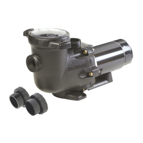
TriStar
75/120 GPM Waterfall Pump Series
The Hayward TriStar Waterfall Pump is specifically engineered for high volume waterfall, spillway, and negativeedge pool
applications, where quiet and efficient delivery of water through low restriction systems is required. It is not intended to be used as
the main pump for the pool water filtration/sanitization system, nor is it intended to be used in applications where water will be
elevated more than (10) feet above the surface of the water in the pool. NOTE To prevent potential injury and to avoid unnecessary
service calls, read this manual carefully and completely.
IMPORTANT – READ CAREFULLY
NOTE The TriStar Waterfall pump uses a lowspeed motor specifically designed for waterfall, spillway, and negativeedge pool
applications. Use only the motor listed on page 12 of this manual as a replacement.
Required:
2" plumbing minimum
Recommended: 2 ½" plumbing or larger
SAVE THIS INSTRUCTION MANUAL
HAYWARD POOL PRODUCTS, INC.
620 DIVISION STREET ELIZABETH, NJ 07207 (908) 3515400
WWW.HAYWARDPOOL.COM
WWW.HAYWARDPOOL.COM USE ONLY HAYWARD GENUINE REPLACEMENT PARTS
Advertisement
Table of Contents

Related Manuals for Hayward TriStar Waterfall


Summary of Contents for Hayward TriStar Waterfall
- Page 1 P/N: IS3600 Rev. A __________________________________________________________________________________________ OWNER’S MANUAL INSTALLATION, OPERATION, & PARTS ™ TriStar 75/120 GPM Waterfall Pump Series The Hayward TriStar Waterfall Pump is specifically engineered for high volume waterfall, spillway, and negativeedge pool applications, where quiet and efficient delivery of water through low restriction systems is required. It is not intended to be used as the main pump for the pool water filtration/sanitization system, nor is it intended to be used in applications where water will be elevated more than (10) feet above the surface of the water in the pool. NOTE To prevent potential injury and to avoid unnecessary service calls, read this manual carefully and completely. IMPORTANT – READ CAREFULLY NOTE The TriStar Waterfall pump uses a lowspeed motor specifically designed for waterfall, spillway, and negativeedge pool applications. Use only the motor listed on page 12 of this manual as a replacement. Required: 2” plumbing minimum Recommended: 2 ½” plumbing or larger SAVE THIS INSTRUCTION MANUAL HAYWARD POOL PRODUCTS, INC. 620 DIVISION STREET ELIZABETH, NJ 07207 (908) 3515400 WWW.HAYWARDPOOL.COM WWW.HAYWARDPOOL.COM USE ONLY HAYWARD GENUINE REPLACEMENT PARTS ...
-
Page 2: Important Safety Instructions
WARNING – This product should be installed and serviced only by a qualified professional. CAUTION – A licensed electrician MUST complete, in full, all electrical installations noted in this manual. Use of nonHayward replacement parts voids warranty. ATTENTION INSTALLER – THIS MANUAL CONTAINS IMPORTANT INFORMATION ABOUT THE INSTALLATION, OPERATION, AND SAFE USE OF THIS PUMP THAT MUST BE FURNISHED TO THE END USER OF THIS PRODUCT. FAILURE TO READ AND FOLLOW ALL INSTRUCTIONS COULD RESULT IN SERIOUS INJURY. WARNING ... - Page 3 – Suction Entrapment Hazard. Suction in suction outlets and/or suction outlet covers which are damaged, broken, cracked, missing, or unsecured cause severe injury and/or death due to the following entrapment hazards: Hair Entrapment Hair can become entangled in suction outlet cover. Limb Entrapment A limb inserted into an opening of a suction outlet sump or suction outlet cover that is damaged, broken, cracked, missing, or not securely attached can result in a mechanical bind or swelling of the limb. Body Suction Entrapment A differential pressure applied to a large portion of the body or limbs can result in an entrapment. Evisceration/ Disembowelment A negative pressure applied directly to the intestines through an unprotected suction outlet sump or suction outlet cover which is damaged, broken, cracked, missing, or unsecured can result in evisceration/disembowelment. Mechanical Entrapment There is potential for jewelry, swimsuits, hair decorations, fingers, toes, or knuckles to be caught in an opening of a suction outlet cover resulting in mechanical entrapment. WARNING To Reduce the risk of Entrapment Hazards: When outlets are small enough to be blocked by a person, a minimum of two functioning suction outlets per pump must be installed. Suction outlets in the same plane (i.e. floor or wall), must be installed a minimum of three feet (3’) [0.91 meter] apart, as measured from near point to near point. Dual suction fittings shall be placed in such locations and distances to avoid “dual blockage” by a user. Dual suction fittings shall not be located on seating areas or on the backrest for such seating areas. The maximum system flow rate shall not exceed the values shown in the “Pipe Sizing Chart” found at the bottom of page 5 of this manual. Never use pool or spa if any suction outlet component is damaged, broken, cracked, missing, or not securely attached. Replace damaged, broken, cracked, missing, or not securely attached suction outlet components immediately. In addition to two or more suction outlets per pump installed in accordance with latest IAF (formerly NSPI) standards and CPSC guidelines, follow all national, state, and local codes applicable. Installation of a vacuum release or vent system, which relieves entrapping suction, is recommended. ™ TriStar Waterfall Pump Series ___ _____ ______________________________ Page 4 of 15 WWW.HAYWARDPOOL.COM USE ONLY HAYWARD GENUINE REPLACEMENT PARTS ...
-
Page 4: General Information
OPEN when starting the circulation system. Failure to do so could result in severe personal injury and/or property damage. WARNING – Never operate or test the circulation system at more than 50 PSI. WARNING – Fire and burn hazard. Motors operate at high temperatures and if they are not properly isolated from any flammable structures or foreign debris they can cause fires, which may cause severe personal injury or death. It is also necessary to allow the motor to cool for at least 20 minutes prior to maintenance to minimize the risk for burns. WARNING – Failure to install according to defined instructions may result in severe personal injury or death. General Information Introduction This manual contains information for the proper installation and operation of the Hayward TriStar Waterfall Pump Series. The instructions in this manual MUST be followed precisely. Failure to install according to defined instructions will void warranty. Product Benefits The new TriStar Waterfall Pump’s advanced fluid dynamic design operates 60% quiter and consumes 60% less electricity than standard single speed pool pumps. Plus, the heavyduty pump and motor construction operates cooler for years of dependability. It is the first to feature a TriLock cam and ramp strainer cover design that closes with less than a quarter turn, and the TriStar’s supersized, smooth norib basket with extra leafholding capacity is easy to clean. ™ TriStar Waterfall Pump Series_________ __ ______________________________ Page 5 of 15 WWW.HAYWARDPOOL.COM USE ONLY HAYWARD GENUINE REPLACEMENT PARTS ... -
Page 5: Installation Instructions
MAXIMUM RECOMMENDED SYSTEM FLOW RATE BY PIPE SIZE Pipe Size Flow Rate Suction Pipe Pipe Size Flow Rate Suction Pipe Pipe Size Flow Rate Suction Pipe [mm] GPM [LPM] Length * [mm] GPM [LPM] Length * [mm] GPM [LPM] Length * 2” [63] 80 [300] 10” 2 ½” [75] 110 [415] 12 ½” 3” [90] 160 [600] 15” * NOTE It is recommended that a minimum length of straight piping (shown as “L” in above diagram), equivalent to 5 pipe size diameters, be used between the pump suction inlet and any plumbing fittings (elbows, valves, etc.). ™ TriStar Waterfall Pump Series _ _____ _______________________________ Page 6 of 15 WWW.HAYWARDPOOL.COM USE ONLY HAYWARD GENUINE REPLACEMENT PARTS ... - Page 6 To avoid dangerous or fatal electrical shock, turn OFF power to motor before working on electrical connections. Ground Fault Circuit Interrupter (GFCI) tripping indicates electrical problem. If GFCI trips and won’t reset, consult electrician to inspect and repair electrical system. Fire Hazard match supply voltage to motor nameplate voltage. Insure that the electrical supply available agrees with the motor’s voltage, phase, and cycle, and that the wire size is adequate for the HP (kW) rating and distance from the power source. NOTE All electrical wiring MUST be performed by a licensed electrician, and MUST conform to local codes and NEC regulations. Use copper conductors only. Motor Brake Horsepower Motor Rated Horsepower Motor Electric V/A Wire Size / Breaker HP (kW) HP (kW) Voltage Amps AWG Amps 0.65 (0.48) 0.50 (0.37) 208 230 / 115 4.0 – 3.6 / 7.2 14 10 ™ TriStar Waterfall Pump Series _ _____ _______________________________ Page 7 of 15 WWW.HAYWARDPOOL.COM USE ONLY HAYWARD GENUINE REPLACEMENT PARTS ...
-
Page 7: Start-Up And Operation
Connect a No. 8 AWG (8.4 mm ) solid copper bonding wire to the pressure wire connector provided on the motor housing and to all metal parts of swimming pool, spa, or hot tub, and to all electrical equipment, metal piping (except gas piping), and conduit within 5 ft. (1.5 m) of inside walls of swimming pool, spa, or hot tub. Wiring WARNING – All wiring must be done by a licensed electrician. Pump MUST be permanently connected to circuit. If other lights or appliances are also on the same circuit, be sure to add their amp loads before calculating wire and circuit breaker sizes. Use the load circuit breaker as the Master OnOff switch. Install a Ground Fault Circuit Interrupter (GFCI) in circuit; it will sense a shortcircuit to ground and disconnect power before it becomes dangerous to pool users. For size of GFCI required and test procedures for GFCI, see manufacturer’s instructions. In case of a power outage, check GFCI for tripping, which will prevent normal pump operation. Reset if necessary. StartUp & Operation Prior to StartUp NOTE If it is necessary to perform a pressure test, prior to initial use to ensure pump is functioning properly, then the following criteria should be maintained for this test: 1. Have a professional perform this test. 2. Ensure all pump and system components are sealed properly to prevent leaks. 3. Remove any trapped air in the system by fully opening filter manual air relief valve until a steady stream of water (not air or air and water mix) is discharged from the valve. 4. Allow no more than 50 psi (345 kPa) at a water temperature no higher than 100° F (38° C). 5. Run pressure test for no longer than 24 hours. Immediately inspect all parts to verify they are intact and functioning properly. WARNING If pump is being pressure tested (50 PSI MAXIMUM), be sure pressure has been released, using the filter manual air relief valve, before removing strainer cover. ™ TriStar Waterfall Pump Series _____ ____ ______________________________Page 8 of 15 WWW.HAYWARDPOOL.COM USE ONLY HAYWARD GENUINE REPLACEMENT PARTS ... -
Page 8: Starting/Priming The Pump
1. STOP PUMP before proceeding. 2. CLOSE VALVES in suction and outlet pipes. 3. RELEASE ALL PRESSURE from pump and piping system using filter manual air relief valve. See filter owner’s manual for more details. 4. If water source is higher than the pump, pump will prime itself when suction and outlet valves are opened. If water source is lower than the pump, unscrew and remove strainer cover; fill strainer housing with water. 5. Clean and lubricate strainer cover Oring with "Jack's 327" if necessary. 6. Replace strainer cover on strainer housing; turn clockwise to tighten cover. NOTE Tighten strainer cover lock ring by hand only (no wrenches). Before restarting pump, see “Starting/Priming the Pump” instructions. ATTENTION – Wait five (5) seconds before restarting pump. Failure to do so may cause reverse rotation of motor and consequent serious pump damage. Turn on power and wait for pump to prime, which may take up to five (5) minutes. Priming time will depend on vertical length of suction lift and horizontal length of suction pipe. If pump does NOT prime within five minutes, stop motor and determine cause. Be sure all suction and discharge valves are open when pump is running. See Troubleshooting Guide. Maintenance § Clean strainer basket regularly. Do NOT strike basket to clean. Inspect strainer cover gasket regularly and replace as necessary. § Hayward pumps have selflubricating motor bearings and shaft seals. No lubrication is necessary. § Keep motor clean. Insure motor air vents are free from obstruction to avoid damage. Do NOT use water to hose off motor. § Occasionally, shaft seals must be replaced, due to wear or damage. Replace with genuine Hayward seal assembly kit. See “Shaft Seal Change Instructions” in this manual. WWW.HAYWARDPOOL.COM USE ONLY HAYWARD GENUINE REPLACEMENT PARTS ... -
Page 9: Storing Pump For Winterization
To avoid dangerous or fatal electrical shock hazard, turn OFF power to motor before draining pump. Failure to disconnect power may result in serious personal injury or death. 1. Drain water level below all inlets to the pool. 2. Remove drain plugs and strainer cover from strainer housing. (See Parts Diagram on page 11 of this manual for pump component locations.) 3. Disconnect pump from mounting pad, wiring (after power has been turned OFF), and piping. 4. Once the pump is removed of water, reinstall the strainer cover and drain plugs. Store pump in a dry area. Shaft Seal Change Instructions IMPORTANT SAFETY INSTRUCTIONS PLEASE READ AND FOLLOW ALL INSTRUCTIONS When servicing electrical equipment, basic safety precautions should always be observed including the following. Failure to follow instructions may result in injury. WARNING – A. To reduce risk of injury, do not permit children to use this product. B. Disconnect all electrical power service to pump before beginning shaft seal replacement. C. Only qualified personnel should attempt rotary seal replacement. Contact your local authorized Hayward Dealer or service center if you have any questions. Exercise extreme care in handling both the rotating and the stationary sections of the twopart replacement seal. Foreign matter or improper handling will easily scratch the graphite and ceramic sealing surfaces. Removing the Motor Assembly (See Parts Diagram on page 11 of this manual for pump component locations.) 1. Remove the six (6) 5/16" x 2" hex head bolts (item #17), which hold the motor assembly to the pump/strainer housing (item #3), using a 1/2" wrench or socket. 2. Slide the motor assembly out of the pump/strainer housing (item #3), exposing the diffuser (item #9). Remove the two diffuser screws (item #7), and pull the diffuser (item #9) off of the seal plate (item #15) to expose the impeller (item #12). WWW.HAYWARDPOOL.COM USE ONLY HAYWARD GENUINE REPLACEMENT PARTS ... - Page 10 STOP Clean all recesses & parts to be reassembled. Inspect gaskets & replace if necessary. Seal Installation (See Parts Diagram on page 11 of this manual for pump component locations.) 8. Clean and lightly lubricate the motor shaft and seal recesses in the seal plate (item #15) with a dilute solution of non granulated liquidtype soap. Gently wipe the polished face of the ceramic seal with a soft cotton cloth. Lubricate the rubber cup on the ceramic seat and press it firmly into the recess of the seal plate (item #15), with the polished ceramic surface facing out. 9. Reassemble the motor to the seal plate (item #15) using the four (4) 3/8” x 1” bolts (item #18), and reattach the motor support (item #20) to the seal plate (item #15). 10. Gently wipe the black, polished surface of the spring seal assembly (item #13) with a soft cotton cloth. 11. Press the spring seal assembly (item #13) onto the motor shaft, with the black polished surface facing the ceramic seat. Replacing the Impeller and Diffuser (See Parts Diagram on page 11 of this manual for pump component locations.) 12. Screw the impeller (item #12) onto the motor shaft in a clockwise direction, and screw the impeller screw (item #10) into the motor shaft in a counterclockwise direction. Tighten snugly by holding motor shaft with wrench as noted in step #4. Place the impeller ring (item #11) back onto the impeller (item #12), with flange facing towards the diffuser (item #9). 13. Place the diffuser (item #9) over the impeller (item #12) and onto the seal plate (item #15), aligning the three pins on the diffuser (item #9) with the three holes on the seal plate (item #15). Replace the two diffuser screws (item #7). Replacing the Motor Assembly (See Parts Diagram on page 11 of this manual for pump component locations.) 14. Reattach motor canopy using the two (2) hex headed screws. Slide the motor assembly, with the diffuser (item #9) in place, into pump/strainer housing (item #3), being careful not to disturb the diffuser gasket (item #8). 15. Fasten assembly to pump/strainer housing (item #3) using the six (6) 5/16" x 2" bolts (item #17). (Be sure housing gasket (item #14) is in place, and lubricated. Replace if damaged). Tighten bolts alternately and evenly to 185 inch pounds according to housing bolt torque pattern detail. WWW.HAYWARDPOOL.COM USE ONLY HAYWARD GENUINE REPLACEMENT PARTS ...
-
Page 11: Replacement Parts
3 SPX3200A Pump Strainer Housing, 2” x 2 1/2” with Drain Plugs, threaded style 1 4 SPX3200DLS Strainer Cover Kit (Includes Strainer Cover, Lock Ring, ORing) 10 SPX3200DLSB Strainer Cover Kit (Biguanide Sanitizer Applications Only; NOT Pressure Testable) 10 5 SPX3200S Strainer Cover ORing 10 6 SPX3200M Strainer Basket 15 7 SPX3200Z8 Diffuser Screw 1 8 SPX4000Z1 Diffuser ORing 10 9 SPX3200B3 Diffuser 1 10 SPX3200Z1 Impeller Screw 1 11 SPX3021R Impeller Ring 1 WWW.HAYWARDPOOL.COM USE ONLY HAYWARD GENUINE REPLACEMENT PARTS ... - Page 12 SPX3200Z211 Housing Insert/Seal Plate Spacer Kit 1 17 SPX3200Z3 Housing Bolt 10 18 SPX3200Z5 Motor Bolt 1 19 SPX4000FG Drain Plug with ORing 10 20 SPX3200GA Bracket, Motor Support, TriStar 1 21 * SPX3200SR Base, Tall Riser, TriStar 1 Pump SKU Detail Model P/N Motor P/N Impeller P/N SP36075EE SPX3605Z1BER SPX3220C SP36120EE SPX3605Z1BER SPX3230CU * STARITE is a registered trademark of StaRite Industries, Inc., which is used herein for identification purposes only. These are retrofit bases for existing STARITE pump installations. StaRite Industries, Inc.is not affiliated with Hayward Pool Products. WWW.HAYWARDPOOL.COM USE ONLY HAYWARD GENUINE REPLACEMENT PARTS ...
-
Page 13: Troubleshooting
Motor Will NOT Start – Check For: Make sure the terminal board connections agree with the wiring diagram on motor data plate label. Be sure motor is wired for available field supply voltage (see pump operating label). 1. Improper or loose wiring connections; open switches or relays; tripped circuit breakers, GFCI’s, or blown fuses. Solution: Check all connections, circuit breakers, and fuses. Reset tripped breakers or replace blown fuses. 2. Manually check rotation of motor shaft for free movement and lack of obstruction. Solution: Refer to Steps 4 & 5 of “Shaft Seal Change Instructions” in this manual. 3. If you have a timer, be certain it is working properly. Bypass it if necessary. Motor Shuts OFF – Check For: 1. Low voltage at motor or power drop (frequently caused by undersized wiring or extension cord use). Solution: Contact qualified professional to check that the wiring gauge is heavy enough. NOTE: Your Hayward pump motor is equipped with an “automatic thermal overload protector.” The motor will automatically shut off if power supply drops before heat damage can build up causing windings to burn out. The “thermal overload protector” will allow the motor to automatically restart once the motor has cooled. It will continue to cut On/Off until the problem is corrected. Be sure to correct cause of overheating. Motor Hums, But Does NOT Start – Check For: 1. Impeller jammed with debris. Solution: Have a qualified repair professional open the pump and remove the debris. Pump Won't Prime, Check For: 1. Empty pump/strainer housing. Solution: Make sure pump/strainer housing is filled with water and cover oring is clean. Ensure oring is properly seated in the cover oring groove. Ensure oring sealing surface is lubricated with “Jack’s 327” and that strainer cover is locked firmly in position. Lubricant will help to create a tighter seal. 2. Loose connections on suction side. ... -
Page 14: Product Registration
4. Air leak in suction (bubbles issuing from return fittings). Solution: Retighten suction and discharge connections using Teflon tape. Inspect other plumbing connections and tighten as required. 5. Plugged, restricted, or damaged impeller. Solution: Replace including new seal assembly. Noisy Pump – Check For: 1. Air leak in suction piping, cavitations caused by restricted or undersized suction line or leak at any joint, low water level in pool, and unrestricted discharge return lines. Solution: Correct suction condition or throttle return lines, if practical. Holding hand over return fitting will sometimes prove this point or putting in a smaller eyeball fitting. 2. Vibration due to improper mounting, etc. Solution: Mount the pump on a level surface and secure the pump to the equipment pad. 3. Foreign matter in pump housing. Loose stones/debris hitting impeller could be cause. Solution: Clean the pump housing. 4. Motor bearings noisy from normal wear, rust, overheating, or concentration of chemicals causing seal damage which will allow chlorinated water to seep into bearings wiping out the grease causing bearing to whine. Solution: All seal leaks should be replaced at once. © Hayward Pool Products, Inc. 2005 All rights reserved. PRODUCT REGISTRATION (Retain For Your Records) DATE OF INSTALLATION ____________________ INITIAL PRESSURE GAUGE READING (CLEAN FILTER) _______________________ PUMP MODEL ________________ HORSEPOWER _______________________ FILTER MODEL ________________ SERIAL NUMBER _______________________ WWW.HAYWARDPOOL.COM USE ONLY HAYWARD GENUINE REPLACEMENT PARTS ... -
Page 15: Warranty Registration Card
Pump housing/strainers which become defective during the warranty period, except as a result of freezing, negligence, improper installation, use or care, or as the result of a use in association with an automatic valving system, shall be repaired, at our option, without charge. All other conditions and terms of the standard warranty apply. Hayward shall not be responsible for cartage, removal and/or reinstallation labor or any other such costs incurred in obtaining warranty replacements. The Hayward Pool Products warranty does not apply to components manufactured by others. For such products, the warranty established by the respective manufacturer will apply. Some states do not allow a limitation on how long an implied warranty lasts, or the exclusion or limitation of incidental or consequential damages, so the above limitation or exclusion may not apply to you. This warranty gives you specific legal rights, and you may also have other rights, which vary from state to state. Hayward Pool Products, Inc. 620 Division Street *Supersedes all previous publications. Elizabeth, NJ 07207 ▲Retain this Warranty Certificate (upper portion) in a safe and convenient location for your records. ▼DETACH HERE: Fill out bottom portion completely and mail within 10 days of purchase/installation, or register online at WWW.HAYWARDPOOL.COM. Mail to: Hayward Pool Products, Inc., 620 Division Street, Elizabeth, NJ 07207, Attn: Warranty Dept. Warranty Registration Card □ □ □ □ Name__________________________________________________ Years pool has been in service less than 1 13 35 510 Address________________________________________________ Purchased from: City______________________ State_________ Zip____________ Company name________________________________________________ Email Address__________________________________________ Address_______________________________________________________ City__________________________ State_________ Zip_______________ Product Purchased ______________________________________ ...
Need help?
Do you have a question about the TriStar Waterfall and is the answer not in the manual?
Questions and answers