Advertisement
Quick Links
Download this manual
See also:
Owner's Manual
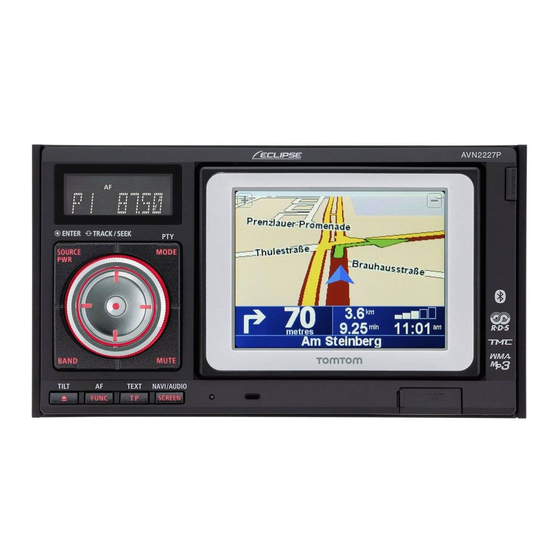
In-Dash Portable Navigation with CD/USB Multi-Source Receiver
INSTALLATION MANUAL
Be sure to read this installation manual thoroughly prior to installation. If installation methods or nonstandard parts
not specified in this installation manual are used, accidents or injury may result.
Professional installation is required to install this system. Eclipse recommends you to have the system installed at
your retailer. Be sure to keep this manual after installation for later reference.
Customer should keep manual for reference.
Contents
Contents
Before
installation
For your safety in using the AVN2227P
Connections
Installation
MODEL
2
3
5
7
8
9
11
Advertisement

Related Manuals for Eclipse AVN 2227P


Summary of Contents for Eclipse AVN 2227P
-
Page 1: Table Of Contents
Professional installation is required to install this system. Eclipse recommends you to have the system installed at your retailer. Be sure to keep this manual after installation for later reference. -
Page 2: Components
Components Components Check that all of the following components are present Check that all of the following components are present Main unit components Main unit x 1 Interconnecting cable Interconnecting cable Hex-head bolt (Power and speaker connector) (Speed pulse, Genuine (Red:M5x8) x 4 (16P) x 1 steering remote control) - Page 3 Also, do not deviate from the installation procedures the main unit does not interfere, nor come in contact with described herein; Eclipse will not be held liable for them. Otherwise, a fire may result. damages including, but not limited to serious injury, death, •...
- Page 4 • • Avoid installing this main unit in places where it may get Eclipse main units and can damage the main unit. Prior to wet, such as near windows, or in places that are moist or powering up the main unit, please make sure the main unit dusty.
-
Page 5: Names And Functions Of Terminals
Names and functions of ter minals Names and functions of ter minals • • Never cut the insulation on the power cable or use it to power any other equipment. If the rated current capacity of the power cable is exceeded, fire and electric shocks may result. •... - Page 6 Cable colours and connection points for connection cables Antenna power supply (Blue) Connect to the automatic-antenna control terminal of the vehicle. Control power supply (Blue/White) Connect the control terminal for the external amplifier, etc. Cellular phone mute Cable (Pink) Connect to the earth output terminal on a mobile phone. Earth (Black) Connect where good body earthing is available.
-
Page 7: Connecting The Vehicle Speed Pulse
The locations where the vehicle speed pulse signal cable may vary depending on the vehicle model and grade. Ask the car dealer or your nearest Eclipse dealer for details. - Connecting point for the vehicle speed pulse signal (example) -... -
Page 8: System Connection Example
System connection e xample System connection e xample • • Never cut the insulation on the power cable or use it to power any other main unit. If the rated current capacity of the power cable is exceeded, fire and electric shocks may result. •... -
Page 9: Installing The Gps Antenna
Installing the GPS antenna Installing the GPS antenna Notes on installation • • The cables should be bound together with tape or a similar securing method (example: cable ties) so that they do not interfere with driving. If it becomes wound or entangled around parts such as the steering wheel, shifting lever, or brake pedal, accidents may result. - Page 10 Choose an installation location on the dashboard which is flat and has a clear view of the sky. • • Select a location that is at least 50 cm. away from the main unit. If this is not done, the GPS measurement precision will drop.
-
Page 11: Installing The Main Unit
Installing the main unit Installing the main unit To maintain proper function, the unit must be mounted less than 30 degrees. If the angle is in excess of 30 Front degrees, CD skipping and improper CD ejection may occur. 30˚ or less Level (reference) Remove the carrying bracket. - Page 12 • • Be careful not to forcefully push on the main unit's of the screw holes in the mounting bracket. display or buttons during installation. This may result in damage to the main unit. "ECLIPSE" is a registered trademark of FUJITSU TEN LIMITED in 54 countries. - 12 -...
Need help?
Do you have a question about the AVN 2227P and is the answer not in the manual?
Questions and answers