Table of Contents
Advertisement
Quick Links
FOR NATURAL GAS OR LP
OWNER INSTRUCTIONS, DO NOT DESTROY
!
Recognize this symbol as an indication of important Safety Information!
NOTE: FLUE GAS TEMPERATURES MUST NOT EXCEED 285
(550
O
F) AT VENT SYSTEM INLET.
THESE INSTRUCTIONS ARE INTENDED AS AN AID TO QUALIFIED, LICENSED
SERVICE PERSONNEL FOR PROPER INSTALLATION, ADJUSTMENT AND
OPERATION OF THIS UNIT. READ THESE INSTRUCTIONS THOROUGHLY
BEFORE ATTEMPTING INSTALLATION OR OPERATION. FAILURE TO FOLLOW
THESE INSTRUCTIONS MAY RESULT IN IMPROPER INSTALLATION, ADJUST-
MENT, SERVICE OR MAINTENANCE POSSIBLY RESULTING IN FIRE, ELECTRI-
CAL SHOCK, CARBON MONOXIDE POISONING, EXPLOSION, PERSONAL
INJURY OR PROPERTY DAMAGE.
DO NOT DESTROY. PLEASE READ CAREFULLY AND KEEP
IN A SAFE PLACE ON JOB SITE FOR FUTURE REFERENCE.
Copyright © 1997, Tjernlund Products, Inc. All rights reserved.
TJERNLUND PRODUCTS, INC.
1601 Ninth Street • White Bear Lake, MN 55110-6794
PHONE (800) 255-4208 • (651) 426-2993 • FAX (651) 426-9547
Visit our web site • www.tjernlund.com
REV. 2 9/97
MODEL
HS-3C
O
C
P/N 8504002
Advertisement
Table of Contents

Related Manuals for TJERNLUND HS-3C CANADIAN 8504002 REV 2 0997


Summary of Contents for TJERNLUND HS-3C CANADIAN 8504002 REV 2 0997
- Page 1 CAL SHOCK, CARBON MONOXIDE POISONING, EXPLOSION, PERSONAL INJURY OR PROPERTY DAMAGE. DO NOT DESTROY. PLEASE READ CAREFULLY AND KEEP IN A SAFE PLACE ON JOB SITE FOR FUTURE REFERENCE. Copyright © 1997, Tjernlund Products, Inc. All rights reserved. P/N 8504002...
-
Page 2: Table Of Contents
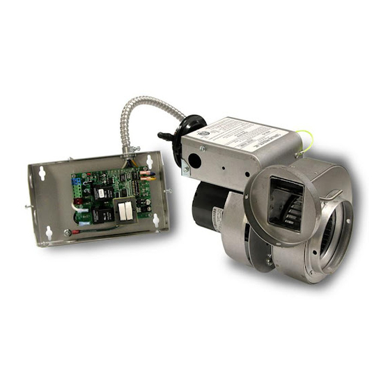
DESCRIPTION The Tjernlund Power Venter model HS-3C is designed to Side Wall or Vertically vent Natural and LP Gas appliances. The HS-3C is supplied with a Fan Proving Switch which will disable the gas valve if a venting malfunction should occur. -
Page 3: Restrictions
INSTALLATION RESTRICTIONS Failure to install, maintain and/or operate the Power Venter in accordance with manufacturer's instructions may result in conditions which can produce bodily injury and property damage. The Power Venter must be installed by a qualified installer in accordance with these instructions and all local codes or in their absence in accordance with the latest edition of The Natural Gas Installation Code (CAN/CGA-B149.1) &... -
Page 4: Vent Hood Location
VENT HOOD LOCATION NOTE: Termination of a Side Wall Vent System with a device other than the Tjernlund VH1 Series Vent Hood could affect system performance and result in a possible safety hazard. Consult Vent Hood instructions for complete installation details. -
Page 5: Power Venter Mounting
POWER VENTER MOUNTING The installer must supply plumber’s strap or 1/4” threaded rod with nuts and washers for mounting. The Power Venter may be mounted in any position as long as the shaft of the motor remains horizontal. The Power Venter housing is single wall, 15.2 CM (6”) must be maintained from all combustible materials. -
Page 6: Fan Proving Switch Installation
FAN PROVING SWITCH INSTALLATION NOTE: It is important that the electrical box is mounted with the Fan Proving Switch in a vertical position. 1. Mount supplied electrical box to a flat surface within 2 feet of the Power Venter with Proving Switch in a vertical position. -
Page 7: Wiring With Single Appliance
MODEL HS-3C WIRING WITH SINGLE APPLIANCE The HS-3C Power Venter is equipped with 2 relays. One is used to activate the Power Venter while the other is used to isolate the Fan Proving Switch from the load of the appliance. The relays and Fan Proving Switch are factory wired for easy installation. The installer needs to complete 3 steps to wire the Power Venter as noted below: 1. - Page 8 MODELS HS-3C CONNECTION DIAGRAMS WITH SINGLE APPLIANCE The diagrams below represent common ways in which the HS-3C Power Venter is interlocked to 24V controlled appliances. Variations of these diagrams are acceptable as long as the Fan Proving Switch isolation circuit is wired to disable the gas valve if a venting mal- function should occur.
-
Page 9: Operation Sequence
If you have any questions about your Power Venter or if it requires adjustment, repair or routine maintenance, we suggest that you contact your installer, contractor or service agency. If you require technical information contact Tjernlund Products, Inc. at 1-800-255-4208. When contacting Tjernlund Products, Inc., please have the following information available:... -
Page 10: Replacement Parts
TJERNLUND LIMITED ONE YEAR WARRANTY Tjernlund Products, Inc. warrants to the original purchaser of this product that the product will be free from defects due to faulty material or workmanship for a period of (1) year from the date of original purchase or delivery to the original purchaser, whichever is earlier. Remedies under this warranty are limited to repairing or replacing, at our option, any product which shall, within the above stated warranty period, be returned to Tjernlund Products, Inc.
Need help?
Do you have a question about the HS-3C CANADIAN 8504002 REV 2 0997 and is the answer not in the manual?
Questions and answers