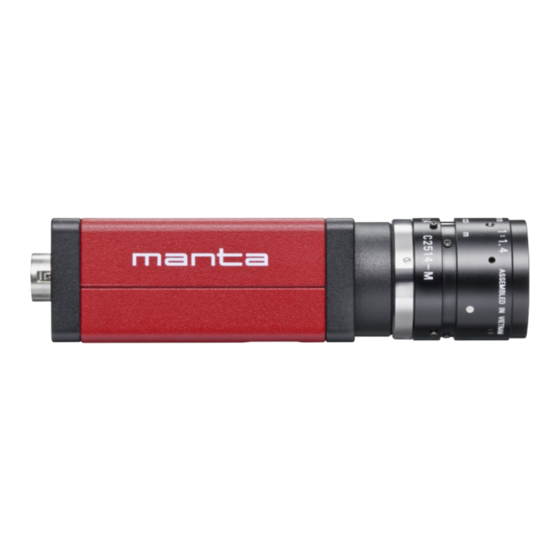
Summarization of Contents
Read before use
Safety
Read these safety instructions to understand hazards and operate Manta cameras safely.
Intended use
Product integration into vision systems by professionals in a B2B setting.
Manta cameras at a glance
Scope of delivery
Details of components included with the Allied Vision camera.
Contact us
Website, email
General contact details via website and email.
Offices
Contact information for Allied Vision offices globally.
Specifications
Applied standards
Standards applied to Manta cameras, such as GigE Vision and GenICam.
Shock and vibration
Testing standards for camera shock and vibration resistance.
Notes on specifications
Information about Manta CCD 1-Tap vs CMOS 2-Tap, serial numbers, and modular options.
Resolution and ROI frame rate
Explanation of ROI frame rate calculation and factors affecting it.
Imaging performance
Data based on EMVA 1288 standard for image sensor characterization.
Specifications common to all models
Table of common specifications for all Manta models.
Model specific specifications
Detailed specifications for specific Manta model series.
Camera feature availability
Availability of image optimization and camera control features across Manta models.
Mechanical dimensions
Tripod adapter
Dimensions and specifications for the Manta camera tripod adapter.
Manta type A camera dimensions
Mechanical dimensions for Manta Type A standard and angled-head housings.
Board level models
Mechanical dimensions for board level Manta cameras with C-Mount and M12-Mount.
C-Mount cross section
Cross section view of C-Mount, including filter and protrusion.
CS-Mount cross section
Cross section view of CS-Mount, including filter and protrusion.
Manta type B camera dimensions
Mechanical dimensions for Manta Type B standard and angled-head housings.
Board level models
Mechanical dimensions for board level Manta Type B cameras.
Filter and lenses
Focal length versus field of view
Tables showing field of view based on sensor size, distance, and focal length.
Model values
Tables providing field of view for various focal lengths for specific Manta series.
Optical filters
Explanation of IR cut filters and protection glass (ASG) used in Manta cameras.
Installing the camera
Touching hot cameras
Safety precautions when handling hot cameras.
Electrostatic discharge
Measures to avoid damage from static electricity (ESD).
Board level cameras
Handling precautions for board level cameras, including ESD and mechanical forces.
Mounting the camera
Instructions on how to mount the camera using M3 threads or a tripod adapter.
Mounting the lens
Guidelines for attaching lenses, keeping optical components clean, and handling sensors.
Configuring the host computer
Requirements for host computer NIC and network configuration for optimal performance.
IP settings
Configuring IP addresses for NICs and cameras for network communication.
Connecting the camera
Connecting the Manta camera using Ethernet cables and recommendations for cable types.
Powering up the camera
Information on camera power adapters and powering methods (DC, PoE).
Powering the camera via PoE
Powering Manta cameras using Power over Ethernet (PoE) and associated requirements.
Connecting to the host application
Connecting the Manta camera to host PC with Vimba Viewer or third-party software.
Configuring the camera
Configuring camera parameters for optimal connection and performance.
Camera interfaces
Back panel
Overview of the rear panel of Manta type A cameras, showing ports and LEDs.
Status LEDs
Description of status LED colors and their meanings for Manta type A models.
Gigabit Ethernet port
Conformity to IEEE 802.3 1000BASE-T standard and cable recommendations.
Camera I/O connections
Details about the general purpose I/O port and Hirose connector.
I/O connector pin assignment
Detailed pin assignment and color coding for the camera I/O connector.
Input block diagram
Schematic showing input signal processing with optocoupler and LP filter.
Output block diagram
Schematic showing output signal processing with optocoupler.
Auto Iris (video type) output description
Description of built-in video type auto iris controls and schematic.
Control signals
Overview of configurable I/O modes and signal control.
Output signals
Description of main output signals like GPO, AcquisitionTriggerReady, and FrameTrigger.
Trigger timing concept
Explanation of the general trigger concept and internal signal waveforms.
Image data flow
Manta model series with CCD sensors
Image data flow diagram for Manta models with CCD sensors.
Manta model series with CMOS sensors
Image data flow diagram for Manta models with CMOS sensors.
Color interpolation (Bayer demosaicing)
Explanation of Bayer demosaicing process for color sensors.
Cleaning optical components
Keep optical components clean
Best practices to prevent foreign substances from entering the camera.
Identifying impurities
How to identify image artifacts caused by impurities on lens, filter, or sensor.
Locating impurities
Procedure to determine if impurities are on the lens, filter, or sensor.
Materials for cleaning optical components
Recommended and prohibited cleaning materials for optical components.
Cleaning Instructions
Workplace conditions and steps for cleaning optical components.
Firmware update
Updating the firmware on your Manta camera
Step-by-step guide to update the camera firmware using the Firmware Loader.
Recovery Mode
How to use recovery mode if the camera is not found by the loader.
Power cycle after firmware updates
Requirement to power cycle the camera after firmware updates.
Appendix
Mechanical dimensions
Mechanical dimensions for non-PoE Manta cameras up to serial number 503323258.
Board level models
Mechanical dimensions for board level Manta C-Mount (non-PoE models).
Back panel
Rear view of non-PoE Manta cameras up to serial number 503323258, showing ports and LEDs.
Camera I/O connector pin assignment
Pin assignment for non-PoE Manta cameras up to serial number 503323258.


Need help?
Do you have a question about the Manta G-040B PoE and is the answer not in the manual?
Questions and answers