
Subscribe to Our Youtube Channel
Related Manuals for Allied Vision Prosilica GT Series


Summary of Contents for Allied Vision Prosilica GT Series
- Page 1 ISION AMERAS Prosilica GT Technical Manual V3.2.0 Allied Vision Technologies GmbH Taschenweg 2a, 07646 Stadtroda, Germany 2019-Nov-14...
-
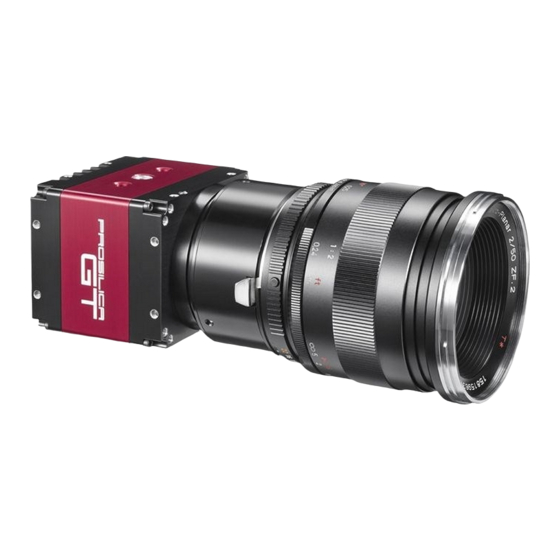
Page 2: Prosilica Gt At A Glance
Prosilica GT cameras are GigE Vision V1.2 and GenICam SFNC V1.2.1 compliant. Scope of delivery Your Allied Vision camera is delivered with the following components: • Prosilica GT GigE Vision camera • Download instructions to gain access to the Prosilica GT Quickstart Guide. The... -
Page 3: Contact Allied Vision
Contact Allied Vision Contact Allied Vision Website To directly contact Allied Vision with any inquiry, go to: www.alliedvision.com/en/meta-header/contact To find an Allied Vision office or distribution partner, go to: www.alliedvision.com/en/about-us/where-we-are Support and general inquiries For all camera-related queries contact us at support@alliedvision.com For all general inquiries, contact us at info@alliedvision.com... -
Page 4: Table Of Contents
Allied Vision software ........ - Page 5 Contents Specifications Applied standards ............... . 36 Shock and vibration.
- Page 6 Contents ROI frame rate............... . 88 Prosilica GT2450 series .
- Page 7 Contents Spectral response ..............136 ROI frame rate.
- Page 8 Contents Gigabit Ethernet port ..............184 Camera I/O connections .
-
Page 9: Document History And Conventions
Document history and conventions This chapter includes: • Document history • Layout styles and symbols used in this manual • Acronyms and terms used in this manual Prosilica GT Technical Manual V3.2.0... -
Page 10: Document History
Document history and conventions Document history Version Date Remarks V3.2.0 2019-Nov-14 • Initial commercial release: Prosilica GT4400 series Sony IMX367 CMOS sensor Specifications, absolute QE plot, spectral response plot, ROI frame rate, image data flow • Initial commercial release: Prosilica GT5400 series Sony IMX387 CMOS sensor Specifications, absolute QE plot, spectral response plot, ROI frame rate, image data flow... - Page 11 Updated all ON Semi absolute QE plots to reflect the Gen 2 CFA material change • Added cable color to camera I/O connector pin assignment including pin assignment figure and cross reference to the Allied Vision I/O cable data sheet • Updated camera I/O connector pin assignment, input triggers, and output signals section •...
- Page 12 Document history and conventions Version Date Remarks V2.9.0 2017-Aug-04 • Corrected exposure value range for Prosilica GT2000 • Changed Cell size terminology to Pixel size • Various other minor improvements and corrections V2.8.1 2016-Aug-16 • Added optical filter information to specification tables •...
- Page 13 Camera smart features and Camera features sections • Added Cleaning optical components chapter to replace Camera cleaning and updated information • Added Contact us section to replace Contacting Allied Vision section • Updated Prosilica GT Large Format lens mount drawings V2.4.1 2015-Sep-15 •...
- Page 14 Specifications, absolute QE plot, spectral response plot, ROI frame rate, EF lens control, image data flow • Updated Allied Vision logo • Changed AVT and Allied Vision Technologies references to Allied Vision • Updated additional references section • Added Prosilica GT3300 with ON Semi KAI-08050 sensor information •...
- Page 15 Added frame rate tables in the Specifications chapter V2.0.8 2013-Jul-05 • Updated the absolute QE plot for Prosilica GT1910 • Added links to Allied Vision GigE Camera and Driver Features document V2.0.7 2013-May-16 • Updated the bit depth and exposure control camera specifications in the Specifications chapter •...
- Page 16 Document history and conventions Version Date Remarks V2.0.4 2012-Sep-21 • Initial commercial release: Prosilica GT2000 series CMOSIS/ams CMV2000 CMOS sensor Specifications, absolute QE plot, ROI frame rate, image data flow • Initial commercial release: Prosilica GT2050 series CMOSIS/ams CMV4000 CMOS sensor Specifications, absolute QE plot, ROI frame rate, image data flow •...
-
Page 17: Manual Conventions
Document history and conventions Manual conventions To give this manual an easily understood layout and to emphasize important information, the following typographical styles and symbols that are used. Styles Style (example) Function Emphasis Some important parts or items of the text are emphasized to make them more visible. - Page 18 Document history and conventions Instructions to avoid malfunctions This symbol indicates important or specific instructions or procedures that are related to product safety. You have to follow these instructions to avoid malfunctions. Practical hint This symbol highlights a practical hint that helps to better understand the camera‘s features and functions, and to make better use of it.
- Page 19 Document history and conventions Acronym or term Description EMVA European Machine Vision Association Electrostatic discharge FIFO First-in first-out GigE Gigabit Ethernet Ground (power) GVSP GigE Vision Streaming Protocol H × V Horizontal × Vertical (sensor resolution measurement) Input/Output KΩ Kiloohm Look-up table MSDS Material safety data sheet...
-
Page 20: Compliance And Intended Use
Compliance and intended use § This chapter includes: • Compliance notifications for the following areas: - Europe (CE) - US (FCC) - Canada (ICES) • Information about application and intended use of the camera • Copyright and trademark statement Prosilica GT Technical Manual V3.2.0... -
Page 21: Compliance Notifications
Compliance and intended use Compliance notifications For customers in Europe Allied Vision has demonstrated the fulfillment of the requirements relating to the Prosilica GT camera family: • Directive 2014/30/EU (Electromagnetic compatibility) • Directive 2011/65/EU, including amendment 2015/863/EU (RoHS) For customers in the US Supplier Declaration of Conformity Prosilica GT GigE cameras comply with Part 15 of the FCC Rules. -
Page 22: For Customers In Canada
Cet appareil est conforme aux normes classe A pour bruits radioélectriques, spécifiées dans le Règlement sur le brouillage radioélectrique. CAN ICES-3 (A) / NMB-3 (A) Avoid electromagnetic interferences For all power and interface connections, only use shielded cables or cables recommended by Allied Vision. Prosilica GT Technical Manual V3.2.0... -
Page 23: Camera Applications And Intended Use
The camera-supporting software can be obtained and installed separately from the camera. Usage of the software is solely the responsibility of the user. • The camera must not be opened. For all repair tasks, contact Allied Vision or one of Allied Vision's authorized representatives. •... -
Page 24: Copyright And Trademarks
All trademarks, logos, and brands cited in this document are property and/or copyright material of their respective owners. Use of these trademarks, logos, and brands does not imply endorsement. Copyright © 2019 Allied Vision GmbH. All rights reserved. Prosilica GT Technical Manual V3.2.0... -
Page 25: Installation And Hardware
Installation and hardware This chapter describes the components required for your vision system including configuring the host computer, NIC settings, and connecting your Prosilica GT camera. Prosilica GT Technical Manual V3.2.0... -
Page 26: Precautions
Installation and hardware Precautions Electrical connections NOTICE ESD is dangerous for electronic devices, especially when tools or hands get in contact with connectors. We recommend measures to avoid damage by ESD: • Unpacking: Remove the camera from its anti-static packaging only when your body is grounded. -
Page 27: Optical Components
See instructions on optics cleaning in this document. We can clean your camera as a service for you, if necessary. For more information, contact Allied Vision support. NOTICE Provide the following conditions to keep dirt and droplets out of the optical system of camera and lens: •... -
Page 28: Mounting The Camera
Installation and hardware NOTICE Many of the lens mount styles available such as M42-Mount, F-Mount, and EF-Mount are not designed for high vibration environments with a heavy lens load. We recommend supporting the lens externally in these environments. NOTICE As monochrome and NIR models don’t have an optical filter, always attach a dust cap when a lens is not attached to minimize the possibility of contaminants falling on the sensor surface. -
Page 29: Large Format Housing
Installation and hardware Large Format housing You can attach the camera to a base using the M3 thread mounting holes built into the top, bottom, sides, and front of the Prosilica GT camera housing and lens mount. Prosilica GT Large Format cameras also have a built-in 1/4-20 tripod mounting hole on two sides. -
Page 30: Optional: Modifying Nic Ip Address
Installation and hardware 3. Under Network Adapters, locate the Ethernet NIC, right-click the entry, and select Update Driver Software in the menu. 4. Select the Search automatically for updated driver software or Browse my computer for driver software. 5. Click Close after the driver has been installed. Optional: Modifying NIC IP address After the initial NIC hardware installation, connect the NIC directly to the camera. -
Page 31: Enabling Jumbo Packets
For desktop systems, use a PCI Express bus NIC. For laptops, use an expansion slot via an ExpressCard®. A list of recommended NICs is available on the Allied Vision website. See the Hardware Selection for Allied Vision GigE Cameras application note. -
Page 32: Connecting Your Camera
C-Mount, CS-Mount, F-Mount, F-Mount PA, M42-Mount, M42-Mount, M58-Mount PA, M58-Mount PA, and Canon EF-Mount PA depending on the model. Lenses can be purchased directly from Allied Vision or from an Allied Vision distribution partner. Users need to select the desired focal length of the lens and appropriate optical format for the target camera model. -
Page 33: Software
• Vimba Viewer or Vimba SDK • Third-party software solutions Powering up the camera A camera power adapter for each GigE camera is available from Allied Vision. See the Specifications chapter for connector definition and voltage specifications. NOTICE • Use only DC power supplies with insulated cases. -
Page 34: Connecting To Host Application
Prosilica GT camera via an Ethernet cable. If your camera is not PoE powered, connect the Hirose cable to power the camera. Allied Vision software All software packages provided by Allied Vision are free of charge and contain the following components: • Drivers •... -
Page 35: Specifications
Specifications This chapter provides: • Applied standards • Technical specifications • Absolute QE plots • Spectral response plots • ROI frame rate plots • Comparison of feature availability in various Prosilica GT camera model series Prosilica GT Technical Manual V3.2.0... -
Page 36: Applied Standards
The GenICam standard consists of multiple modules that specify tasks to be solved. Allied Vision cameras and software make use of these modules, like the SFNC that standardizes feature names and types via an XML file or the transport layer interface (GenTL) that is used to grab images. -
Page 37: Notes On Specifications
Prosilica GT color models with ON Semi sensors now use sensors with the latest generation 2 CFA materials. For more information, see the Product Change Notification on the Allied Vision website. Frame memory Normally, an image is captured and transported in consecutive steps. The image is taken, read out from the sensor, digitized, and sent over the GigE network. - Page 38 Specifications Number of frames The number of frames ( ) depends on resolution, pixel StreamHoldCapacity format, and GVSP packet size. The stated number of frames is typical for full resolution, 8-bit pixel format ( ), and a Mono8 Bayer8 GevSCPSPacketSize = 8192 bytes per packet.
- Page 39 Specifications Sensor tap mode (CCD models only) With quad-tap sensor mode you can achieve a higher frame rate than with single-tap mode. With single-tap sensor mode, you can achieve an image certain to be free of any tap-boundary artifacts. You can also use single-tap mode if you experience tap imbalance issues with your camera.
- Page 40 Specifications Model series Sensor tap mode Prosilica GT4905 Quad-tap, Single-tap switchable in Vimba 2.0 or later Prosilica GT4907 Quad-tap, Single-tap switchable in Vimba 2.0 or later Prosilica GT6600 Quad-tap, Single-tap switchable in Vimba 2.0 or later Table 8: Sensor tap modes for CCD model series (sheet 2 of 2) Absolute QE plots Before reading the specifications tables All measurements were done without protection glass or IR cut filter.
- Page 41 Specifications Spectral response plots The curves in the spectral response plots shown in this chapter were calculated from measured quantum efficiencies at 448 nm, 529 nm, and 632 nm. The shape of the curve is taken from the sensor data sheet, but the values have been adjusted based on these measured values.
-
Page 42: Specifications Common To All Models
Specifications Specifications common to all models The following table provides specifications common to all Prosilica GT models. Feature Specification Optional lens mount • Standard and Extended housing models: C-Mount, CS-Mount, Birger EF-Mount, M42-Mount • Large Format models: C-Mount , EF-Mount PA, F-Mount, F-Mount PA, M42-Mount, M42-Mount PA, M58-Mount, M58-Mount PA, TFL-Mount Default optical filter... -
Page 43: Prosilica Gt1290 Series
Specifications Prosilica GT1290 series The following table provides model series specifications. The values are valid for Prosilica GT1290 and GT1290C models. For specifications common to all models, Specifications common to all Prosilica GT models. Specification Feature Prosilica GT1290 Prosilica GT1290C Sensor model Sony ICX445ALA Sony ICX445AQA... - Page 44 Specifications Specification Feature Prosilica GT1290 Prosilica GT1290C Propagation delay (t 30 ns for non-isolated I/O; 70 ns for isolated I/O Operating temperature -20 °C to +65 °C ambient temperature (without condensation) Storage temperature -20 °C to +70 °C ambient temperature (without condensation) Camera dimensions 86 ×...
-
Page 45: Absolute Qe
Specifications Absolute QE Blue QE Green QE Red QE Monochrome QE Sony ICX445 absolute QE 1000 Wavelength [nm] Figure 3: Prosilica GT1290 (Sony ICX445) absolute QE Spectral response Blue Response Green Response Red Response Monochrome Response 0.3000 Sony ICX445 spectral response 0.2000 0.1000 0.0000... -
Page 46: Roi Frame Rate
Specifications ROI frame rate Width = 1280 pixels Single tap mode 1000 ROI height [pixels] Figure 5: Prosilica GT1290 frame rate as a function of ROI height Height Frame rate Height Frame rate Height Frame rate 33.3 58.8 232.4 35.3 70.5 289.5 39.2... -
Page 47: Prosilica Gt1380 Series
Specifications Prosilica GT1380 series The following table provides model series specifications. The values are valid for Prosilica GT1380 and GT1380C models. For specifications common to all models, Specifications common to all Prosilica GT models. Specification Feature Prosilica GT1380 Prosilica GT1380C Sensor model Sony ICX285AL Sony ICX285AQ... - Page 48 Specifications Specification Feature Prosilica GT1380 Prosilica GT1380C Trigger jitter ±20 ns Propagation delay (t 30 ns for non-isolated I/O; 70 ns for isolated I/O Operating temperature -20 °C to +65 °C ambient temperature (without condensation) Storage temperature -20 °C to +70 °C ambient temperature (without condensation) Camera dimensions 86 ×...
-
Page 49: Absolute Qe
Specifications Absolute QE Blue QE Green QE Red QE Monochrome QE Sony ICX285 absolute QE 1000 Wavelength [nm] Figure 6: Prosilica GT1380 (Sony ICX285) absolute QE Spectral response Blue Response Green Response Red Response Monochrome Response 0.3000 Sony ICX285 spectral response 0.2000 0.1000 0.0000... -
Page 50: Roi Frame Rate
Specifications ROI frame rate Width = 1360 pixels Single tap mode 1050 ROI height [pixels] Figure 8: Prosilica GT1380 frame rate as a function of ROI height Height Frame rate Height Frame rate Height Frame rate 1024 30.5 47.2 132.7 1000 31.1 54.1... -
Page 51: Prosilica Gt1600 Series
Specifications Prosilica GT1600 series The following table provides model series specifications. The values are valid for Prosilica GT1600 and GT1600C models. For specifications common to all models, Specifications common to all Prosilica GT models. Specification Feature Prosilica GT1600 Prosilica GT1600C Sensor model Sony ICX274AL Sony ICX274AQ... - Page 52 Specifications Specification Feature Prosilica GT1600 Prosilica GT1600C Propagation delay (t 30 ns for non-isolated I/O; 70 ns for isolated I/O Operating temperature -20 °C to +65 °C ambient temperature (without condensation) Storage temperature -20 °C to +70 °C ambient temperature (without condensation) Camera dimensions 86 ×...
-
Page 53: Absolute Qe
Specifications Absolute QE Blue QE Green QE Red QE Monochrome QE Sony ICX274 absolute QE 1000 Wavelength [nm] Figure 9: Prosilica GT1600 (Sony ICX274) absolute QE Spectral response Blue Response Green Response Red Response Monochrome Response 0.3000 Sony ICX274 spectral response 0.2000 0.1000 0.0000... -
Page 54: Roi Frame Rate
Specifications ROI frame rate Width = 1620 pixels Single tap mode 1120 1260 ROI height [pixels] Figure 11: Prosilica GT1600 frame rate as a function of ROI height Height Frame rate Height Frame rate Height Frame rate 1220 25.8 48.5 220.2 1100 28.4... -
Page 55: Prosilica Gt1660
Specifications Prosilica GT1660 The following table provides model series specifications. The values are valid for Prosilica GT1660 models. For specifications common to all models, see Specifications common to all Prosilica GT models. Discontinuation Prosilica GT1660C was previously discontinued and the last time buy period ended on September 15, 2019. - Page 56 Specifications Specification Feature Prosilica GT1660 Trigger jitter ±20 ns Propagation delay (t 30 ns for non-isolated I/O; 70 ns for isolated I/O Operating temperature -20 °C to +60 °C ambient temperature (without condensation) Storage temperature -20 °C to +70 °C ambient temperature (without condensation) Camera dimensions 92 ×...
-
Page 57: Absolute Qe
Specifications Absolute QE Monochrome QE ON Semi KAI 02050 absolute QE 1000 1050 Wavelength [nm] Figure 12: Prosilica GT1660 (ON Semi KAI-02050 Gen 2) absolute QE Spectral response Monochrome Response 0.200 ON Semi KAI 02050 spectral response 0.150 0.100 0.050 0.000 950 1000 1050 1100 Wavelength [nm]... -
Page 58: Roi Frame Rate
Specifications ROI frame rate Width = 1600 pixels Quad tap mode 1000 1100 1200 ROI height [pixels] Figure 14: Prosilica GT1660 frame rate as function of ROI height Height Frame rate Height Frame rate Height Frame rate 1200 62.1 105.6 207.8 1000 74.3... -
Page 59: Prosilica Gt1910 Series
Specifications Prosilica GT1910 series The following table provides model series specifications. The values are valid for Prosilica GT1910 and GT1910C models. For specifications common to all models, Specifications common to all Prosilica GT models. Discontinuation Due to ON Semi’s discontinuation of this sensor the Prosilica GT1910 series has been discontinued with the last time buy period ending on March 1, 2020. - Page 60 Specifications Specification Feature Prosilica GT1910 Prosilica GT1910C Decimation X/Y Horizontal and vertical: 1, 2, 4, 8 factor Sensor taps Quad-tap Single-tap switchable in Vimba Viewer 2.0 or later Power consumption External power: 5.1 W at 12 VDC Power over Ethernet: 6.3 W Trigger latency 2.2 µs Trigger jitter...
-
Page 61: Absolute Qe
Specifications Absolute QE Blue QE Green QE Red QE Monochrome QE ON Semi KAI 02150 absolute QE 1000 1050 Wavelength [nm] Figure 15: Prosilica GT1910 (ON Semi KAI-02150 Gen 2) absolute QE Spectral response Blue Response Green Response Red Response Monochrome Response 0.200 ON Semi KAI 02150 spectral response... -
Page 62: Roi Frame Rate
Specifications ROI frame rate Width = 1920 pixels Quad tap mode 1000 1100 ROI height [pixels] Figure 17: Prosilica GT1910 frame rate as a function of ROI height Height Frame rate Height Frame rate Height Frame rate 1080 57.5 95.3 199.9 1000 62.1... -
Page 63: Prosilica Gt1920 Series
Specifications Prosilica GT1920 series The following table provides model series specifications. The values are valid for Prosilica GT1920 and GT1920C models. For specifications common to all models, Specifications common to all Prosilica GT models. Specification Feature Prosilica GT1920 Prosilica GT1920 Sensor model Sony ICX674ALG Sony ICX674AQG... - Page 64 Specifications Specification Feature Prosilica GT1920 Prosilica GT1920 Trigger latency 2 µs Trigger jitter ±20 ns Propagation delay (t 30 ns for non-isolated I/O; 70 ns for isolated I/O Operating temperature -20 °C to +60 °C ambient temperature (without condensation) Storage temperature -20 °C to +70 °C ambient temperature (without condensation) Camera dimensions 92 ×...
-
Page 65: Absolute Qe
Specifications Absolute QE Blue QE Green QE Red QE Monochrome QE Sony ICX674 absolute QE 1000 Wavelength [nm] Figure 18: Prosilica GT1920 (Sony ICX674) absolute QE Spectral response Blue Response Green Response Red Response Monochrome Response 0.3000 Sony ICX674 spectral response 0.2000 0.1000 0.0000... -
Page 66: Roi Frame Rate
Specifications ROI frame rate Width = 1936 pixels Quad tap mode 1000 1125 1250 1375 1500 ROI height [pixels] Figure 20: Prosilica GT1920 frame rate as function of ROI height Height Frame rate Height Frame rate Height Frame rate 1456 40.7 69.3 132.2... -
Page 67: Prosilica Gt1930 Series
Specifications Prosilica GT1930 series The following table provides model series specifications. The values are valid for Prosilica GT1930 and GT1930C models. For specifications common to all models, Specifications common to all Prosilica GT models. Specification Feature Prosilica GT1930 Prosilica GT1930C Sensor model Sony IMX174LLJ Sony IMX174LQJ... - Page 68 Available for main board and sensor board. Resolution: 0.031; Accuracy: ±1 °C For more information on CRA, contact Allied Vision support. The Prosilica GT1930 housing lens protrusion is 2.3 mm shorter than other standard housings. Table 28: Prosilica GT1930 model series specifications (sheet 2 of 2)
-
Page 69: Absolute Qe
Specifications Absolute QE Blue QE Green QE Red QE Monochrome QE Sony IMX174 absolute QE 1000 Wavelength [nm] Figure 21: Prosilica GT1930 (Sony IMX174) absolute QE Spectral response Blue Response Green Response Red Response Monochrome Response 0.4000 Sony IMX174 spectral response 0.3000 0.2000 0.1000... -
Page 70: Roi Frame Rate
Specifications ROI frame rate 1890 Width = 1936 pixels 1680 1470 1260 1050 1050 1225 ROI height [pixels] Figure 23: Prosilica GT1930 frame rate as a function of ROI height Height Frame rate Height Frame rate Height Frame rate 1216 50.8 102.0 751.5... -
Page 71: Prosilica Gt1930L Series
Specifications Prosilica GT1930L series The following table provides model series specifications. The values are valid for Prosilica GT1930L and GT1930LC models. For specifications common to all models, Specifications common to all Prosilica GT models. Specification Feature Prosilica GT1930L Prosilica GT1930LC Sensor model Sony IMX174LLJ Sony IMX174LQJ... - Page 72 Temperature monitoring Available for main board and sensor board. Resolution: 0.031; Accuracy: ±1 °C For more information on CRA, contact Allied Vision support. Selects the site which temperature is reported. For more information on DeviceStatus, see the GigE Features Reference.
-
Page 73: Absolute Qe
Specifications Absolute QE Blue QE Green QE Red QE Monochrome QE Sony IMX174 absolute QE 1000 Wavelength [nm] Figure 24: Prosilica GT1930L (Sony IMX174) absolute QE Spectral response Blue Response Green Response Red Response Monochrome Response 0.4000 Sony IMX174 spectral response 0.3000 0.2000 0.1000... -
Page 74: Roi Frame Rate
Specifications ROI frame rate 1890 Width = 1936 pixels 1680 1470 1260 1050 1050 1225 ROI height [pixels] Figure 26: Prosilica GT1930L frame rate as a function of ROI height Height Frame rate Height Frame rate Height Frame rate 1216 50.8 102.0 751.5... -
Page 75: Prosilica Gt2000 Series
Specifications Prosilica GT2000 series The following table provides model series specifications. The values are valid for Prosilica GT2000, GT2000NIR, and GT2000C models. For specifications common to all models, see Specifications common to all Prosilica GT models. Specification Feature Prosilica GT2000, GT2000NIR Prosilica GT2000C Sensor model CMOSIS/ams CMV2000... - Page 76 Specifications Specification Feature Prosilica GT2000, GT2000NIR Prosilica GT2000C Storage temperature -20 °C to +70 °C ambient temperature (without condensation) Camera dimensions 86 × 53.3 × 33 mm (L × W × H) Mass (typical) 210 g Temperature monitoring Available for main board only. Resolution: 0.031;...
-
Page 77: Absolute Qe
Specifications Absolute QE Blue QE Green QE Red QE Monochrome QE CMOSIS/ams CMV2000 absolute QE 1000 1100 Wavelength [nm] Figure 27: Prosilica GT2000 and GT2000C (CMOSIS/ams CMV2000) absolute QE Monochrome QE NIR QE CMOSIS/ams CMV2000 absolute QE 1000 1100 Wavelength [nm] Figure 28: Prosilica GT2000NIR (CMOSIS/ams CMV2000 NIR) absolute QE Prosilica GT Technical Manual V3.2.0... -
Page 78: Spectral Response
Specifications Spectral response Blue Response Green Response Red Response Monochrome Response 0.4000 CMOSIS/ams CMV2000 spectral response 0.3000 0.2000 0.1000 0.0000 1000 Wavelength [nm] Figure 29: Prosilica GT2000 and GT2000C (CMOSIS/ams CMV2000) spectral response Monochrome Response NIR Response 0.4000 CMOSIS/ams CMV2000 spectral response 0.3000 0.2000 0.1000... -
Page 79: Roi Frame Rate
Specifications ROI frame rate 5000 Width = 2048 pixels 4500 4000 3500 3000 2500 2000 1500 1000 1000 1100 ROI height [pixels] Figure 31: Prosilica GT2000 frame rate as a function of ROI height Height Frame rate Height Frame rate Height Frame rate 1088... -
Page 80: Prosilica Gt2050 Series
Specifications Prosilica GT2050 series The following table provides model series specifications. The values are valid for Prosilica GT2050, GT2050NIR, and GT2050C models. For specifications common to all models, see Specifications common to all Prosilica GT models. Specification Feature Prosilica GT2050, GT2050NIR Prosilica GT2050C Sensor model CMOSIS/ams CMV4000... - Page 81 Specifications Specification Feature Prosilica GT2050, GT2050NIR Prosilica GT2050C Storage temperature -20 °C to +70 °C ambient temperature (without condensation) Camera dimensions 86 × 53.3 × 33 mm (L × W × H) Mass (typical) 210 g Temperature monitoring Available for main board only. Resolution: 0.031;...
-
Page 82: Absolute Qe
Specifications Absolute QE Blue QE Green QE Red QE Monochrome QE CMOSIS/ams CMV4000 absolute QE 1000 1100 Wavelength [nm] Figure 32: Prosilica GT2050 (CMOSIS/ams CMV4000) absolute QE Monochrome QE NIR QE CMOSIS/ams CMV4000 absolute QE 1000 1100 Wavelength [nm] Figure 33: Prosilica GT2050NIR (CMOSIS/ams CMV4000 NIR) absolute QE Prosilica GT Technical Manual V3.2.0... -
Page 83: Spectral Response
Specifications Spectral response Blue Response Green Response Red Response Monochrome Response 0.4000 CMOSIS/ams CMV4000 spectral response 0.3000 0.2000 0.1000 0.0000 1000 Wavelength [nm] Figure 34: Prosilica GT2050 (CMOSIS/ams CMV4000) spectral response Monochrome Response NIR Response 0.4000 CMOSIS/ams CMV4000 spectral response 0.3000 0.2000 0.1000... -
Page 84: Roi Frame Rate
Specifications ROI frame rate 5000 Width = 2048 pixels 4500 4000 3500 3000 2500 2000 1500 1000 1200 1500 1800 2100 ROI height [pixels] Figure 36: Prosilica GT2050 frame rate as a function of ROI height Height Frame rate Height Frame rate Height Frame rate... -
Page 85: Prosilica Gt2300 Series
Specifications Prosilica GT2300 series The following table provides model series specifications. The values are valid for Prosilica GT2300 and GT2300C models. For specifications common to all models, Specifications common to all Prosilica GT models. Discontinuation Due to ON Semi’s discontinuation of this sensor the Prosilica GT2300 series has been discontinued with the last time buy period ending on March 1, 2020. - Page 86 Specifications Specification Feature Prosilica GT2300 Prosilica GT2300C Decimation X/Y Horizontal and vertical: 1, 2, 4, 8 factor Sensor taps Quad-tap Single-tap switchable in Vimba Viewer 2.0 or later Power consumption External power: 4.9 W at 12 VDC Power over Ethernet: 6.0 W Trigger latency 2.2 µs Trigger jitter...
-
Page 87: Absolute Qe
Specifications Absolute QE Blue QE Green QE Red QE Monochrome QE ON Semi KAI 04050 absolute QE 1000 1050 Wavelength [nm] Figure 37: Prosilica GT2300 (ON Semi KAI-04050 Gen 2) absolute QE Spectral response Blue Response Green Response Red Response Monochrome Response 0.200 ON Semi KAI 04050 spectral response... -
Page 88: Roi Frame Rate
Specifications ROI frame rate Width = 2336 pixels Quad tap mode 1050 1200 1350 1500 1650 1800 ROI height [pixels] Figure 39: Prosilica GT2300 frame rate as a function of ROI height Height Frame rate Height Frame rate Height Frame rate 1752 29.3 54.8... -
Page 89: Prosilica Gt2450 Series
Specifications Prosilica GT2450 series The following table provides model series specifications. The values are valid for Prosilica GT2450 and GT2450C models. For specifications common to all models, Specifications common to all Prosilica GT models. Specification Feature Prosilica GT2450 Prosilica GT2450C Sensor model Sony ICX625ALA Sony ICX625AQA... - Page 90 Specifications Specification Feature Prosilica GT2450 Prosilica GT2450C Trigger jitter ±20 ns Propagation delay (t 30 ns for non-isolated I/O; 70 ns for isolated I/O Operating temperature -20 °C to +65 °C ambient temperature (without condensation) Storage temperature -20 °C to +70 °C ambient temperature (without condensation) Camera dimensions 86 ×...
-
Page 91: Absolute Qe
Specifications Absolute QE Blue QE Green QE Red QE Monochrome QE Sony ICX625 absolute QE 1000 Wavelength [nm] Figure 40: Prosilica GT2450 (Sony ICX625) absolute QE Spectral response Blue Response Green Response Red Response Monochrome Response 0.3000 Sony ICX625 spectral response 0.2000 0.1000 0.0000... -
Page 92: Roi Frame Rate
Specifications ROI frame rate Width = 2448 pixels Dual tap mode 1200 1500 1800 2100 ROI height [pixels] Figure 42: Prosilica GT2450 frame rate as a function of ROI height Height Frame rate Height Frame rate Height Frame rate 2050 15.0 1000 25.9... -
Page 93: Prosilica Gt2460 Series
Specifications Prosilica GT2460 series The following table provides model series specifications. The values are valid for Prosilica GT2460 and GT2460C models. For specifications common to all models, Specifications common to all Prosilica GT models. Specification Feature Prosilica GT2460 Prosilica GT2460C Sensor model Sony IMX264LLR Sony IMX264LQR... - Page 94 211 g Temperature monitoring Available for main board and sensor board. Resolution: 0.031; Accuracy: ±1 °C For more information on CRA, contact Allied Vision support. Table 42: Prosilica GT2460 model series specifications (sheet 2 of 2) Prosilica GT Technical Manual V3.2.0...
-
Page 95: Absolute Qe
Specifications Absolute QE Blue QE Green QE Red QE Monochrome QE Sony IMX264 absolute QE plot 1000 Wavelength [nm] Figure 43: Prosilica GT2460 (Sony IMX264) absolute QE Spectral response Blue Response Green Response Red Response Monochrome Response 0.4000 Sony IMX264 spectral response 0.3000 0.2000 0.1000... -
Page 96: Roi Frame Rate
Specifications ROI frame rate 1650 Width = 2464 pixels 1485 1320 1155 1200 1500 1800 2100 ROI height [pixels] Figure 45: Prosilica GT2460 frame rate as a function of ROI height Height Frame rate Height Frame rate Height Frame rate 2056 23.7 63.0... -
Page 97: Prosilica Gt2750 Series
Specifications Prosilica GT2750 series The following table provides model series specifications. The values are valid for Prosilica GT2750 and GT2750C models. For specifications common to all models, Specifications common to all Prosilica GT models. Specification Feature Prosilica GT2750 Prosilica GT2750C Sensor model Sony ICX694ALG Sony ICX694AQG... - Page 98 Specifications Specification Feature Prosilica GT2750 Prosilica GT2750C Trigger latency 2.2 µs Trigger jitter ±20 ns Propagation delay (t 30 ns for non-isolated I/O; 70 ns for isolated I/O Operating temperature -20 °C to +60 °C ambient temperature (without condensation) Storage temperature -20 °C to +70 °C ambient temperature (without condensation) Camera dimensions 92 ×...
-
Page 99: Absolute Qe
Specifications Absolute QE Blue QE Green QE Red QE Monochrome QE Sony ICX694 absolute QE 1000 Wavelength [nm] Figure 46: Prosilica GT2750 (Sony ICX694) absolute QE Spectral response Blue Response Green Response Red Response Monochrome Response 0.4000 Sony ICX694 spectral response 0.3000 0.2000 0.1000... -
Page 100: Roi Frame Rate
Specifications ROI frame rate Width = 2750 pixels Quad tap mode 1000 1200 1400 1600 1800 2000 2200 ROI height [pixels] Figure 48: Prosilica GT2750 frame rate as a function of ROI height Height Frame rate Height Frame rate Height Frame rate 2200 19.8... -
Page 101: Prosilica Gt3300
Specifications Prosilica GT3300 The following table provides model series specifications. The values are valid for Prosilica GT3300 cameras. For specifications common to all models, see Specifications common to all Prosilica GT models. Discontinuation Prosilica GT3300C was discontinued and the last time buy period ended on September 15, 2019. - Page 102 Specifications Specification Feature Prosilica GT3300 Power consumption External power: 5.6 W at 12 VDC Power over Ethernet: 6.9 W Trigger latency 2.2 µs Trigger jitter ±20 ns Propagation delay (t 30 ns for non-isolated I/O; 70 ns for isolated I/O Operating temperature -20 to +60 °C ambient temperature (without condensation) Storage temperature...
-
Page 103: Absolute Qe
Specifications Absolute QE Monochrome QE ON Semi KAI 08050 absolute QE 1000 1050 1100 Wavelength [nm] Figure 49: Prosilica GT3300 (ON Semi KAI-08050 Gen 2) absolute QE Spectral response Monochrome Response 0.200 ON Semi KAI 08050 spectral response 0.150 0.100 0.050 0.000 1000... -
Page 104: Roi Frame Rate
Specifications ROI frame rate Width = 3296 pixels Quad tap mode 1000 1250 1500 1750 2000 2250 2500 ROI height [pixels] Figure 51: Prosilica GT3300 frame rate as a function of ROI height Height Frame rate Height Frame rate Height Frame rate 2472 14.8... -
Page 105: Prosilica Gt3400 Series
Specifications Prosilica GT3400 series The following table provides model series specifications. The values are valid for Prosilica GT3400 and GT3400C models. For specifications common to all models, Specifications common to all Prosilica GT models. Specification Feature Prosilica GT3400 Prosilica GT3400C Sensor model Sony ICX814ALG Sony ICX814AQG... - Page 106 Specifications Specification Feature Prosilica GT3400 Prosilica GT3400C Trigger jitter ±20 ns Propagation delay (t 30 ns for non-isolated I/O; 70 ns for isolated I/O Operating temperature -20 °C to +60 °C ambient temperature (without condensation) Storage temperature -20 °C to +70 °C ambient temperature (without condensation) Camera dimensions 92 ×...
-
Page 107: Absolute Qe
Specifications Absolute QE Blue QE Green QE Red QE Monochrome QE Sony ICX814 absolute QE 1000 Wavelength [nm] Figure 52: Prosilica GT3400 (Sony ICX814) absolute QE Spectral response Blue Response Green Response Red Response Monochrome Response 0.4000 Sony ICX814 spectral response 0.3000 0.2000 0.1000... -
Page 108: Roi Frame Rate
Specifications ROI frame rate Width = 3384 pixels Quad tap mode 1000 1250 1500 1750 2000 2250 2500 2750 ROI height [pixels] Figure 54: Prosilica GT3400 frame rate as a function of ROI height Height Frame rate Height Frame rate Height Frame rate 2704... -
Page 109: Prosilica Gt4090 Series
Specifications Prosilica GT4090 series The following table provides model series specifications. The values are valid for Prosilica GT4090 and GT4090NIR models. For specifications common to all models, Specifications common to all Prosilica GT models. Specification Feature Prosilica GT4090 Prosilica GT4090NIR Sensor model ON Semi PYTHON 12K ON Semi PYTHON 12K... -
Page 110: Absolute Qe
Temperature monitoring Available for main board and sensor board. Resolution: 0.031; Accuracy: ±1 °C For more information on CRA, contact Allied Vision support. Table 53: Prosilica GT4090 model series specifications (sheet 2 of 2) Absolute QE Figure 55: Prosilica GT4090 (ON Semi PYTHON 12K) absolute QE... -
Page 111: Roi Frame Rate
Specifications ROI frame rate 3100 Width = 4096 pixels 2790 2480 2170 1860 1550 8 bit pixel formats 1240 10 bit pixel formats 1240 1550 1860 2170 2480 2790 3100 ROI height [pixels] Figure 56: Prosilica GT4090 frame rate as a function of ROI height Height Frame rate Height... -
Page 112: Prosilica Gt4096 Series
Specifications Prosilica GT4096 series The following table provides model series specifications. The values are valid for Prosilica GT4096 and GT4096NIR models. For specifications common to all models, Specifications common to all Prosilica GT models. Specification Feature Prosilica GT4096 Prosilica GT4096NIR Sensor model ON Semi PYTHON 16K ON Semi PYTHON 16K... -
Page 113: Absolute Qe
Specifications Specification Feature Prosilica GT4096 Prosilica GT4096NIR Storage temperature -20 °C to +70 °C ambient temperature (without condensation) Camera dimensions 96 × 66 × 53.3 mm (L × W × H) Mass 372 g Temperature monitoring Available for main board and sensor board. Resolution: 0.031;... -
Page 114: Roi Frame Rate
Specifications ROI frame rate 3100 Width = 4096 pixels 2790 2480 2170 1860 1550 8 bit pixel formats 1240 10 bit pixel formats 820 1230 1640 2050 2460 2870 3280 3690 4100 ROI height [pixels] Figure 58: Prosilica GT4096 frame rate as a function of ROI height Height Frame rate Height... -
Page 115: Prosilica Gt4400 Series
Specifications Prosilica GT4400 series The following table provides model series specifications. The values are valid for Prosilica GT4400 and GT4400C models. For specifications common to all models, Specifications common to all Prosilica GT models. Specification Feature Prosilica GT4400 Prosilica GT4400C Sensor model Sony IMX367LLA Sony IMX367LQA... - Page 116 372 g Temperature monitoring Available for main board and sensor board. Resolution: 0.031; Accuracy: ±1 °C For more information on CRA, contact Allied Vision support. Table 59: Prosilica GT4400 model series specifications (sheet 2 of 2) Prosilica GT Technical Manual V3.2.0...
-
Page 117: Absolute Qe
Specifications Absolute QE Blue QE Green QE Red QE Monochrome QE Sony IMX342, IMX367, IMX387 absolute QE plot 1000 Wavelength [nm] Figure 59: Prosilica GT4400 (Sony IMX367) absolute QE Spectral response Blue Response Green Response Red Response Monochrome Response 0.4000 Sony IMX342, IMX367, IMX387 spectral response 0.3000 0.2000... -
Page 118: Roi Frame Rate
Specifications ROI frame rate Figure 61: Prosilica GT4400 frame rate as a function of ROI height Height Frame rate Height Frame rate Height Frame rate 4436 6.12 1200 22.58 265.26 4000 6.79 1000 27.07 306.46 3500 7.77 33.83 362.82 3000 9.05 45.03 444.58... -
Page 119: Prosilica Gt4905 Series
Specifications Prosilica GT4905 series The following table provides model series specifications. The values are valid for Prosilica GT4905 and GT4905C models. For specifications common to all models, Specifications common to all Prosilica GT models. Discontinuation Due to ON Semi’s discontinuation of this sensor the Prosilica GT4905 series has been discontinued with the last time buy period ending on March 1, 2020. - Page 120 Specifications Specification Feature Prosilica GT4905 Prosilica GT4905C Decimation Horizontal and vertical: 1, 2, 4, 8 factor Sensor taps Quad-tap Single-tap switchable in Vimba Viewer 2.0 or later Power consumption External power: 7.3 W at 12 VDC Power over Ethernet: 9.0 W Trigger latency 2.5 µs Trigger jitter...
-
Page 121: Absolute Qe
Specifications Absolute QE Blue QE Green QE Red QE Monochrome QE ON Semi KAI 16050 absolute QE 1000 1050 Wavelength [nm] Figure 62: Prosilica GT4905 (ON Semi KAI-16050 Gen 2) absolute QE Spectral response Blue Response Green Response Red Response Monochrome Response 0.200 ON Semi KAI 16050 spectral response... -
Page 122: Roi Frame Rate
Specifications ROI frame rate Width = 4896 pixels Quad tap mode 1200 1500 1800 2100 2400 2700 3000 3300 ROI height [pixels] Figure 64: Prosilica GT4905 frame rate as a function of ROI height Height Frame rate Height Frame rate Height Frame rate 3264... -
Page 123: Prosilica Gt4907 Series
Specifications Prosilica GT4907 series The following table provides model series specifications. The values are valid for Prosilica GT4907 and GT4907C models. For specifications common to all models, Specifications common to all Prosilica GT models. Discontinuation Due to ON Semi’s discontinuation of this sensor the Prosilica GT4907 series has been discontinued with the last time buy period ending on March 1, 2020. - Page 124 Specifications Specification Feature Prosilica GT4907 Prosilica GT4907C Decimation X/Y Horizontal and vertical: 1, 2, 4, 8 factor Sensor taps Quad-tap Single-tap switchable in Vimba Viewer 2.0 or later Power consumption External power: 7.7 W at 12 VDC Power over Ethernet: 9.5 W Trigger latency 2.5 µs Trigger jitter...
-
Page 125: Absolute Qe
Specifications Absolute QE Blue QE Green QE Red QE Monochrome QE ON Semi KAI 16070 absolute QE 1000 1050 Wavelength [nm] Figure 65: Prosilica GT4907 (ON Semi KAI-16070 Gen 2) absolute QE Spectral response Blue Response Green Response Red Response Monochrome Response 0.250 ON Semi KAI 16070 spectral response... -
Page 126: Roi Frame Rate
Specifications ROI frame rate Width = 4864 pixels Quad tap mode 1300 1625 1950 2275 2600 2925 3250 ROI height [pixels] Figure 67: Prosilica GT4907 frame rate as a function of ROI height Height Frame rate Height Frame rate Height Frame rate 3232 1800... -
Page 127: Prosilica Gt5120 Series
Specifications Prosilica GT5120 series The following table provides model series specifications. The values are valid for Prosilica GT5120 and GT5120NIR models. For specifications common to all models, Specifications common to all Prosilica GT models. Specification Feature Prosilica GT5120 Prosilica GT5120NIR Sensor model ON Semi PYTHON 25K ON Semi PYTHON 25K... -
Page 128: Absolute Qe
Temperature monitoring Available for main board and sensor board. Resolution: 0.031; Accuracy: ±1 °C For more information on CRA, contact Allied Vision support. Table 67: Prosilica GT5120 model series specifications (sheet 2 of 2) Absolute QE Figure 68: Prosilica GT5120 (ON Semi PYTHON 25K) absolute QE... -
Page 129: Roi Frame Rate
Specifications ROI frame rate 3000 Width = 5120 pixels 2700 2400 2100 1800 1500 8 bit pixel formats 1200 10 bit pixel formats 1040 1560 2080 2600 3120 3640 4160 4680 5200 ROI height [pixels] Figure 69: Prosilica GT5120 frame rate as a function of ROI height Height Frame rate Height... -
Page 130: Prosilica Gt5400 Series
Specifications Prosilica GT5400 series The following table provides model series specifications. The values are valid for Prosilica GT5400 and GT5400C models. For specifications common to all models, Specifications common to all Prosilica GT models. Specification Feature Prosilica GT5400 Prosilica GT5400C Sensor model Sony IMX387LLA Sony IMX387LQA... - Page 131 372 g Temperature monitoring Available for main board and sensor board. Resolution: 0.031; Accuracy: ±1 °C For more information on CRA, contact Allied Vision support. Table 70: Prosilica GT5400 model series specifications (sheet 2 of 2) Prosilica GT Technical Manual V3.2.0...
-
Page 132: Absolute Qe
Specifications Absolute QE Blue QE Green QE Red QE Monochrome QE Sony IMX342, IMX367, IMX387 absolute QE plot 1000 Wavelength [nm] Figure 70: Prosilica GT5400 (Sony IMX387) absolute QE Spectral response Blue Response Green Response Red Response Monochrome Response 0.4000 Sony IMX342, IMX367, IMX387 spectral response 0.3000 0.2000... -
Page 133: Roi Frame Rate
Specifications ROI frame rate Figure 72: Prosilica GT5400 frame rate as a function of ROI height Height Frame rate Height Frame rate Height Frame rate 3048 7.14 1000 21.96 220.74 3000 7.33 27.42 255.7 2500 36.48 303.84 2000 10.99 54.49 374.29 1500 14.67... -
Page 134: Prosilica Gt6400 Series
Specifications Prosilica GT6400 series The following table provides model series specifications. The values are valid for Prosilica GT6400 and GT6400C models. For specifications common to all models, Specifications common to all Prosilica GT models. Specification Feature Prosilica GT6400 Prosilica GT6400C Sensor model Sony IMX342LLA Sony IMX342LQA... - Page 135 372 g Temperature monitoring Available for main board and sensor board. Resolution: 0.031; Accuracy: ±1 °C For more information on CRA, contact Allied Vision support. Table 72: Prosilica GT6400 model series specifications (sheet 2 of 2) Prosilica GT Technical Manual V3.2.0...
-
Page 136: Absolute Qe
Specifications Absolute QE Blue QE Green QE Red QE Monochrome QE Sony IMX342, IMX367, IMX387 absolute QE plot 1000 Wavelength [nm] Figure 73: Prosilica GT6400 (Sony IMX342) absolute QE Spectral response Blue Response Green Response Red Response Monochrome Response 0.4000 Sony IMX342, IMX367, IMX387 spectral response 0.3000 0.2000... -
Page 137: Roi Frame Rate
Specifications ROI frame rate Figure 75: Prosilica GT6400 frame rate as a function of ROI height Height Frame rate Height Frame rate Height Frame rate 4860 3.82 1500 12.38 163.01 4500 4.13 1200 15.46 191.36 4000 4.65 1000 18.57 222.29 3500 5.31 23.16... -
Page 138: Prosilica Gt6600 Series
Specifications Prosilica GT6600 series The following table provides model series specifications. The values are valid for Prosilica GT6600 and GT6600C models. For specifications common to all models, Specifications common to all Prosilica GT models. Discontinuation Due to ON Semi’s discontinuation of this sensor the Prosilica GT6600 series has been discontinued with the last time buy period ending on March 1, 2020. - Page 139 Specifications Specification Feature Prosilica GT6600 Prosilica GT6600C Decimation X/Y Horizontal and vertical: 1, 2, 4, 8 factor Sensor taps Quad-tap Single-tap switchable in Vimba Viewer 2.0 or later Power consumption External power: 6.6 W at 12 VDC Power over Ethernet: 8.1 W Trigger latency 2.5 µs Trigger jitter...
-
Page 140: Absolute Qe
Specifications Absolute QE Blue QE Green QE Red QE Monochrome QE ON Semi KAI 29050 absolute QE 1000 1050 Wavelength [nm] Figure 76: Prosilica GT6600 (ON Semi KAI-29050 Gen 2) absolute QE Spectral response Blue Response Green Response Red Response Monochrome Response 0.200 ON Semi KAI 29050 spectral response... -
Page 141: Roi Frame Rate
Specifications ROI frame rate Width = 6576 pixels Quad tap mode 1200 1600 2000 2400 2800 3200 3600 4000 4400 ROI height [pixels] Figure 78: Prosilica GT6600 frame rate as a function of ROI height Height Frame rate Height Frame rate Height Frame rate 4384... -
Page 142: Prosilica Gt Model Series Comparison
Specifications Prosilica GT model series comparison Model series Sensor model Sensor type Sensor format Resolution Frame rate GT1290 Sony ICX445 Type 1/3 1280 × 960 33.3 fps GT1380 Sony ICX285 Type 2/3 1360 × 1024 30.5 fps GT1600 Sony ICX274 Type 1/1.8 1620 ×... - Page 143 Specifications Figure 79: Frame rate comparison Prosilica GT Technical Manual V3.2.0...
-
Page 144: Camera Feature Comparison
Specifications Camera feature comparison Prosilica GT cameras support a number of standard and extended features. The following table identifies a selection of capabilities and compares the availability of features in Prosilica GT camera models. Some features are firmware dependent, refer to the GigE Firmware Release Notes for more information. Standard and extended format models Image optimization features ✔... -
Page 145: Large Format Models
Specifications Camera control features ✔ ✔ ✔ ✔ ✔ ✔ ✔ ✔ ✔ ✔ ✔ ✔ ✔ ✔ ✔ P-Iris and DC-Iris lens control EF lens control ... - Page 146 Specifications Image optimization features ✔ ✔ ✔ ✔ ✔ ✔ ✔ ✔ ✔ ✔ Decimation X/Y ✔ ✔ ✔ Fixed Pattern Noise Correction ✔ ✔ ✔ ✔ ✔ ✔ ✔ ✔ ✔ ✔ Gamma correction ✔...
-
Page 147: Mechanical Dimensions
Mechanical dimensions This chapter includes: • Mechanical drawings and dimensions of standard, extended, and Large Format housings, and tripod adapter • Sensor position accuracy • Maximum protrusion and filter diameter for C-Mount Prosilica GT Technical Manual V3.2.0... -
Page 148: Standard Format Housing
Mechanical dimensions The Prosilica GT family supports a range of sensor formats. To support this sensor variety, three housing formats are used: • Prosilica GT standard format housing • Prosilica GT extended format housing • Prosilica GT Large Format housing Prosilica GT cameras are available with various lens mount options. - Page 149 Mechanical dimensions Model series: Prosilica GT1930 Adjustable C-Mount M3×0.5 3.0 (16x) 65.2 29.9 30.5 11.4 M2-0.4 3 (2x) 26.7 20.6 19.1 70.5 53.3 65.2 Figure 81: Prosilica GT1930 C-Mount standard format housing dimensions Prosilica GT Technical Manual V3.2.0...
-
Page 150: Cs-Mount
11.4 M2-0.4 3 (2x) 70.5 53.3 65.2 Figure 82: CS-Mount standard format housing dimensions Contact the Allied Vision Sales team to purchase the Prosilica GT standard housing camera with CS-Mount option (order code Prosilica GT...-01). Prosilica GT Technical Manual V3.2.0... - Page 151 M2-0.4 3 (2x) 70.5 53.3 65.2 Figure 83: Prosilica GT1930 CS-Mount standard format housing dimensions Contact the Allied Vision Sales team to purchase the Prosilica GT1930 standard housing camera with CS-Mount option (order code Prosilica GT...-01). Prosilica GT Technical Manual V3.2.0...
-
Page 152: Extended Format Housing
30.5 11.4 M2-04 3 (2x) 76.2 53.3 70.9 12.3 Figure 84: C-Mount extended format housing dimensions Contact the Allied Vision Sales team to purchase the Prosilica GT3300 camera with C-Mount option (order code Prosilica GT...-07). Prosilica GT Technical Manual V3.2.0... -
Page 153: Cs-Mount
11.4 M2-0.4 3 (2x) 76.2 53.3 70.9 Figure 85: CS-Mount extended format housing dimensions Contact the Allied Vision Sales team to purchase the Prosilica GT extended housing camera with CS-Mount option (order code Prosilica GT...-07). Prosilica GT Technical Manual V3.2.0... -
Page 154: Birger Ef-Mount
11.4 76.2 27.6 70.9 Figure 86: Birger EF-Mount extended format housing dimensions Contact the Allied Vision Sales team to purchase the Prosilica GT extended format housing camera with Birger EF-Mount option (order code Prosilica GT...-09). Prosilica GT Technical Manual V3.2.0... -
Page 155: F-Mount
11.4 M3-0.4 3 (2x) 28.7 76.2 70.9 Figure 87: F-Mount extended format housing dimensions Contact the Allied Vision Sales team to purchase the Prosilica GT extended housing camera with F-Mount option (order code Prosilica GT...-03). Prosilica GT Technical Manual V3.2.0... -
Page 156: M42-Mount
M2-04 3 (2x) 59.7 11.4 76.2 27.7 70.9 Figure 88: M42-Mount extended format housing dimensions Contact the Allied Vision Sales team to purchase the Prosilica GT extended format housing camera with M42-Mount option (order code Prosilica GT...-31). Prosilica GT Technical Manual V3.2.0... -
Page 157: Large Format Housing
M2x3 (2x) 59.9 27.9 6 (2x) 2 sides Figure 89: C-Mount Large Format housing dimensions Contact the Allied Vision Sales team to purchase the Prosilica GT series camera with C-Mount option (order code Prosilica GT...-07). Prosilica GT Technical Manual V3.2.0... -
Page 158: Ef-Mount Pa
EF-Mount 6 (2x) 2 sides 27.9 Figure 90: EF-Mount PA Large Format housing dimensions Contact the Allied Vision Sales team to purchase the Prosilica GT series camera with EF-Mount PA option (order code Prosilica GT...-18). Prosilica GT Technical Manual V3.2.0... -
Page 159: F-Mount (Default)
Mechanical dimensions F-Mount (default) Model series: Prosilica GT1930L, GT4090, GT4096, GT4400, GT4905, GT4907, GT5120, GT5400, GT6400, GT6600 1/4-20 Tripod M3×4 (4x) 2 Sides Mount 2 Sides 27.9 28 26 48.3 12.7 M3×4 (4x) 2 Sides 11.4 48.3 53.3 53.3 26.8 53.3 Legacy-style M2×3 (2x) -
Page 160: F-Mount Pa
66 28 6 (2x) 2 Sides 27.9 Figure 92: F-Mount PA Large Format housing dimensions Contact the Allied Vision Sales team to purchase the Prosilica GT series camera with F-Mount PA option (order code Prosilica GT...-03). Prosilica GT Technical Manual V3.2.0... -
Page 161: M42-Mount Pa
66 28 6 (2x) 2 Sides 27.9 Figure 93: M42-Mount PA Large Format housing dimensions Contact the Allied Vision Sales team to purchase the Prosilica GT series camera with M42-Mount PA option (order code Prosilica GT...-25). Prosilica GT Technical Manual V3.2.0... -
Page 162: M42-Mount
M2×3 (2x) 25.8* M42-Mount 59.7 66 28 27.9 Figure 94: M42-Mount Large Format housing dimensions Contact the Allied Vision Sales team to purchase the Prosilica GT series camera with M42-Mount option (order code Prosilica GT...-31). Prosilica GT Technical Manual V3.2.0... -
Page 163: M58-Mount Pa
66 28 6 (2x) 2 Sides 27.9 Figure 95: M58-Mount PA Large Format housing dimensions Contact the Allied Vision Sales team to purchase the Prosilica GT series camera with M58-Mount PA option (order code Prosilica GT...-13). Prosilica GT Technical Manual V3.2.0... -
Page 164: M58-Mount
M2×3 (2x) 13.5 27.9 6 (2x) 2 sides Figure 96: M58-Mount Large Format housing dimensions Contact the Allied Vision Sales team to purchase the Prosilica GT series camera with M58-Mount option (order code Prosilica GT...-12). Prosilica GT Technical Manual V3.2.0... -
Page 165: Tfl-Mount (35Mm × 0.75)
53.3 59.9 27.9 6 (2x) 2 sides Figure 97: TFL-Mount Large Format housing dimensions Contact the Allied Vision Sales team to purchase the Prosilica GT series camera with TFL Mount option (order code Prosilica GT...-40). Prosilica GT Technical Manual V3.2.0... -
Page 166: Tripod Adapter
Tripod adapter Prosilica GT standard and extended housing cameras can be mounted on a camera tripod by using the Prosilica GT tripod adapter. Contact the Allied Vision Sales team to purchase the Prosilica GT series tripod adapter (order code 02-5036A). 60.0 0.50 x 45.00... -
Page 167: 1/40-20 Tripod Mount For Large Format Cameras
Mechanical dimensions 1/40-20 tripod mount for Large Format cameras Prosilica GT Large Format cameras can be mounted on a camera tripod by using the 1/4-20 tripod mount thread integrated into the camera housing. Tripod Mount Hole Figure 99: Integrated tripod mount threads for Prosilica GT Large Format cameras Prosilica GT Technical Manual V3.2.0... -
Page 168: Lens Protrusion
Mechanical dimensions Lens protrusion Standard and extended format cameras C-Mount Lens protrusion is the distance from outer edge of C-Mount ring to contact point of first surface internal to C-Mount ring. For color cameras, this surface is the IR cut or IR pass filter holder. -
Page 169: Large Format Cameras
Mechanical dimensions Model Lens protrusion [mm] Model Lens protrusion [mm] Prosilica GT1380C 9.64 Prosilica GT2300 13.64 Prosilica GT1600 13.64 Prosilica GT2300C 9.43 Prosilica GT1600C 9.32 Prosilica GT2450 13.64 Prosilica GT1660 13.64 Prosilica GT2450C 9.27 Prosilica GT1910 13.64 Prosilica GT2460 14.404 Prosilica GT1910C 9.43 Prosilica GT2460C... - Page 170 Mechanical dimensions TFL-Mount Figure 102: Cross section of Prosilica GT Large Format camera front assembly with TFL-Mount M58-Mount Distance to sensor die (12.71 mm Lens protrusion for monochrome cameras (7.04 mm) Lens protrusion for color cameras (5.59 mm) Sensor die Front plate Figure 103: Cross section of Prosilica GT Large Format camera front assembly with M58-Mount...
-
Page 171: Flange Focal Distance
Mechanical dimensions NOTICE Avoid damage from unsuitable lenses. To protect camera and lens, use lenses only up to the allowed maximum protrusion, as listed in the following table. Flange focal distance Standard and extended cameras C-Mount Flange focal distance is the optical distance from the mounting flange to image sensor die. -
Page 172: Large Format Cameras
When the locking ring is loose, unthread the ring a few turns from the camera face. Contact the Allied Vision Sales team to purchase the hexagonal lens adjustment wrench for Prosilica GT cameras with C -Mount or CS-Mount locking ring (order code 02-5003A). - Page 173 Mechanical dimensions Adjustment of F-Mount The F-Mount is adjusted at the factory and does not require adjusting. If for some reason the lens mount requires adjustment, use the following method. M3 Set Screw: 3 Places F-Mount Front Assembly Figure 105: Prosilica GT Large Format with F-Mount isometric view Adjusting the F-Mount Attach F-Mount compatible lens Use an F-Mount compatible lens that allows an infinity focus.
- Page 174 Mechanical dimensions C-Mount Flange focal distance Image sensor die SECTION A-A Flange focal distance: Monochrome cameras: 17.526 mm nominal, 16.0 minimum, 18.5 mm maximum Color cameras: 17.892 mm nominal, 16.0 mm minimum, 18.5 mm maximum Figure 106: C-Mount (Large Format models) flange focal distance Prosilica GT Technical Manual V3.2.0...
- Page 175 Mechanical dimensions M42-Mount PA Flange focal distance = 45.46 mm Image sensor die SECTION A-A Figure 107: M42-Mount PA flange focal distance M42-Mount Flange focal distance = 45.46 mm Image sensor die SECTION A-A Figure 108: M42-Mount flange focal distance Prosilica GT Technical Manual V3.2.0...
- Page 176 Mechanical dimensions M58-Mount Flange focal distance: came [12.3 15.8 came [11. 15.8 Figure 109: M58-Mount flange focal distance The M58-Mount PA flange focal distance is 46.50 mm. Prosilica GT Technical Manual V3.2.0...
-
Page 177: Calibration Variation
Mechanical dimensions TFL-Mount Flange focal distance Image sensor die SECTION A-A Flange focal distance: Monochrome cameras: 17.526 mm nominal, 17.126 minimum, 18.526 mm maximum Color cameras: 17.892 mm nominal, 17.126 mm minimum, 18.526 mm maximum Figure 110: TFL-Mount flange focal distance Calibration variation Flange focal distance is the optical distance from the lens mounting flange to image sensor die. -
Page 178: Pa Mounts
Mechanical dimensions PA mounts Prosilica GT cameras allow planarity adjustment of the mount relative to the camera sensor. Adjustment can be made for overall flange focal distance (Z distance), and planarity (Z-tilt). The following steps describe Z adjustment using a standard EF lens and a target. -
Page 179: Sensor Position Accuracy
Mechanical dimensions Sensor position accuracy Camera body Camera body Pixel area Pixel area Sensor case Sensor case Figure 112: Sensor position accuracy The following table defines the manufacturing accuracy of fitting sensors into Prosilica GT cameras. Unless stated otherwise, the following values are applicable. Criteria Subject Properties... -
Page 180: Optical Filters
Mechanical dimensions Optical filters All Prosilica GT color models are equipped with an infrared block filter (IR cut filter). This filter prevents infrared light from passing to the sensor. In the absence of an IR cut filter, images are dominated by red and are incapable of being properly color balanced. -
Page 181: Camera Interfaces
Camera interfaces This chapter includes: • A general description of the inputs and outputs (including trigger features) • I/O connector pin assignments • I/O block diagrams • A general description of trigger rules including timing diagram and definitions Prosilica GT Technical Manual V3.2.0... -
Page 182: Back Panel
Camera interfaces Back panel Standard and extended format housing Figure 114: Ports and LEDs (standard and extended housing) LED 1 LED 2 Gigabit Ethernet port Gigabit Ethernet cable mounting threads Hirose I/O port Auto iris port Large Format cameras do not have an auto iris port. Table 85: Ports and LEDs Prosilica GT Technical Manual V3.2.0... -
Page 183: Large Format Housing
Camera interfaces Large Format housing Figure 115: Port and LEDs (Large Format housing) LED 1 LED 2 Gigabit Ethernet port Gigabit Ethernet cable mounting threads Hirose I/O port Table 86: Ports and LEDs Prosilica GT Technical Manual V3.2.0... -
Page 184: Status Leds
GigE host controller cards, see www.alliedvision.com/en/support/technical-papers-knowledge-base. A standard PCI GigE host controller card is available for purchase from Allied Vision. Order code: 02-3002A (Intel Pro 1000/GT, PCI, 1 port). Contact the Allied Vision Sales team for additional GigE host controllers. -
Page 185: Camera I/O Connections
Camera interfaces Camera I/O connections The GPIO port uses a Hirose HR10-10R-12PA(73) connector on the camera side. The mating cable connector is Hirose HR10A-10P-12S. Safety-related instructions to avoid malfunctions Read all Notes and Cautions in the Hardware and Installation chapter before using the Hirose I/O connector. - Page 186 Non-isolated Output 2 White/Brown maximum 50 µA (SyncOut2) Table 88: Camera I/O connector pin assignment and color coding (sheet 2 of 2) For cable color and pin out information, see the Allied Vision I/O cable data sheet, www.alliedvision.com/en/support/technical-documentation/accessories-data-she ets. BLUE PINK...
-
Page 187: I/O Definition
Camera interfaces I/O definition Camera power The camera can be powered through the Hirose I/O port, via Pin 1 Camera GND and Pin 2 Camera Power, or through the Gigabit Ethernet port when using a PoE supported NIC, switch, or injector. Cameras powered by both the Hirose I/O port and the Gigabit Ethernet port will use the power provided by Hirose I/O port only. - Page 188 Camera interfaces In 1 (Non-isolated) In 1 is not electrically isolated and can be used when environmental noise is insignificant and faster trigger response is required. The required trigger signal is low voltage TTL 3.3 volts. Tie trigger ground to Camera GND to complete the trigger circuit.
-
Page 189: Output Signals
Camera interfaces Isolated IN GND The Isolated IN GND connection provides the user ground reference and return path for In 2. It is recommended that the ground wiring be physically close to the In2 wiring to prevent parasitic coupling. For example, a good cable design connects In 2 to one conductor of a twisted pair, Isolated IN GND to the second conductor of the same twisted pair. - Page 190 Camera interfaces Out1 and Out2 (Non-isolated) Out 1 and Out 2 signals are not electrically isolated and can be used when environmental electrical noise is insignificant and faster trigger response is required. Tie signal ground to Camera GND to complete the external circuit. The output signal is a low voltage TTL, maximum 3.3 volts.
- Page 191 Camera interfaces Out 3 and Out 4 signals are optically isolated and require the user to provide a voltage level, Isolated Out Power. The Out3 and Out4 signal should be grounded by adding an external load resistor as shown in the following figure and table. Isolated Out Power can be configured between 5 to 24 volts.
-
Page 192: Lens Control
• Video-type auto-iris lenses are not supported. • Motorized CCTV lenses are not supported. Read lens descriptions carefully before purchasing or contact your Allied Vision Sales representative. For example, a motorized iris lens may be a bipolar single axis motorized lens, and... - Page 193 Camera interfaces P-Iris mode PIN number PIN function Voltage Maximum current Coil 1 A (output) 0 V or 3.3 V 200 mA Coil 2 A (output) 0 V or 3.3 V 200 mA Coil 2 B (output) 0 V or 3.3 V 200 mA Coil 1 B (output) 0 V or 3.3 V...
-
Page 194: Prosilica Gt Large Format Cameras
Camera interfaces Operating P-Iris lenses P-Iris controls are described further in the following documents: • Vimba and third-party software users: GigE Features Reference • PvAPI users: GigE Camera and Driver Attributes document Operate P-Iris lenses 1. Connect a P-Iris lens to the camera before powering up the camera. 2. -
Page 195: Camera Trigger
Camera interfaces Operate EF lenses NOTICE The maximum power supplied via PoE is 13 watts. EF lens power requirements will vary from lens to lens; however, typical ratings are in the 3 to 4 watt range. If your lens plus camera power requirements exceed 13 watts, power the camera via the Hirose I/O port. -
Page 196: Trigger Definitions
Camera interfaces The following diagram explains the general trigger concept for CMOS-sensor models. Readout me Trigger latency Registered Exposure start delay exposure me User trigger Note: Ji er at the beginning Logic trigger of an exposure has no e ect on the length of exposure. - Page 197 Camera interfaces Trigger rules The user trigger pulse width should be at least three times the width of the trigger latency as indicated in the Specifications chapter. • The end of exposure will always trigger the next Readout. • The end of exposure must always end after the current Readout. •...
-
Page 198: Image Data Flow
Image data flow This chapter presents diagrams that illustrate data flow and bit resolution of the image data. Prosilica GT Technical Manual V3.2.0... -
Page 199: Prosilica Gt Model Series With Ccd Sensors
Image data flow A complete listing of camera features, including definitions can be found on the Allied Vision Technical Documentation webpage. • Vimba and third-party users: GigE Features Reference • PvAPI users: GigE Camera and Driver Attributes document Prosilica GT model series with CCD sensors... -
Page 200: Prosilica Gt Model Series With Cmos Sensors
Image data flow Prosilica GT model series with CMOS sensors Model series: Prosilica GT1930, GT1930L, GT2460, GT4400, GT5400, GT6400 Figure 126: Image data flow for Prosilica GT1930, GT1930L, GT2460, GT4400, GT5400, and GT6400 model series Prosilica GT Technical Manual V3.2.0... - Page 201 Image data flow Model series: Prosilica GT2000, GT2050 Calibrated Calibrated Gain Offset Sensor Vertical ROI Offset Analog Analog Analog Analog Internal sensor components Gain Horizontal ROI White balance Defect Mask 12 bit 12 bit 12 bit 12 bit Bayer Hue, Saturation, Gamma Look up Table Interpolation...
- Page 202 Image data flow Model series: Prosilica GT4090, GT4096, GT5120 Calibrated Calibrated Horizontal ROI Sensor Vertical ROI Gain Offset Analog Analog Analog Analog Internal sensor components Horizontal Defect Pixel Digital Gain FPNC Processing Binning Correction 10 bit 10 bit 10 bit 10 bit FPNC Memory Histogram...
-
Page 203: Cleaning Optical Components
Cleaning optical components This chapter describes safety instructions and cautions for cleaning lenses, optical filters, protection glass, or sensors. Prosilica GT Technical Manual V3.2.0... -
Page 204: Keep Optical Components Clean
Read these instructions before you contact Allied Vision or your Allied Vision distribution partner for assistance. Contact Allied Vision or your Allied Vision distribution partner if you are not familiar with the procedures as previously described. Keep optical components clean The best way to ensure the camera remains clean is to avoid penetration of foreign substances into the camera. -
Page 205: Locating Impurities
IR cut filter or protection glass, it is probably on the sensor. NOTICE A pin spanner wrench (Allied Vision order code: E9020001) suitable for IR filter removal is available for purchase from Allied Vision for all Prosilica GT cameras except Prosilica GT Large Format cameras. -
Page 206: Cleaning Instructions
Cleaning optical components Optical cleaning liquid material safety data sheets Read the material safety data sheet (MSDS) for the optical cleaning liquid before cleaning your camera and optics. The MSDS provides important information including hazard identification, first aid measures, handling and storage, and PPE. Cleaning Instructions Workplace conditions: •... -
Page 207: Cleaning With Compressed Air
If you notice that the camera lens or sensor is not clean after attempting to clean twice, or if you have any questions regarding cleaning your camera, contact your Allied Vision distribution partner. Cleaning with compressed air We do not recommend cleaning Prosilica GT cameras with compressed air. -
Page 208: Firmware Update
Firmware update This chapter includes instructions on updating the firmware on your Prosilica GT camera. Prosilica GT Technical Manual V3.2.0... - Page 209 Firmware update If new firmware contains a new feature or control, saved camera UserSets or ConfigFiles will be invalidated and erased! Before loading new firmware, backup your current camera settings. • Vimba Viewer: select the Save Camera Settings icon from the Cameras window to export the camera settings file (XML format) to the host computer.
- Page 210 Firmware update 2. Click Next. The Firmware Loader displays a list of firmware included in the package. 3. Click Next. Select your camera model on this page. Select the Use recovery mode check box if the connected GigE camera is not found by the firmware loader, or if the GigE camera is listed as unavailable.
- Page 211 Firmware update 4. Click Next. 5. Click Upload to start the update. The existing firmware will be erased and the new firmware will be uploaded to the camera. Prosilica GT Technical Manual V3.2.0...
- Page 212 Firmware update 6. The Firmware Loader displays a success status upon completion. Click Quit to exit the loader. You must always power cycle the camera after a firmware upgrade or downgrade. Prosilica GT Technical Manual V3.2.0...
-
Page 213: Index
Index Index adjustment GenICam............36 C-Mount ..........171 Gigabit Ethernet F-Mount ..........173 Cable length..........2 Interface ............2 Gigabit Ethernet interface ......184 GigE host controller......... 184 camera GND........187 GigE Vision............36 camera power........185 Category 6............32 camera............. 185 cleaning RS232 and external power ...... - Page 214 Index sensor row readout cycles ...... 196 Specifications ........... 35 spectral transmission P-Iris lens..........192 IRC30 filter..........180 Power status LEDs ............. 184 DC ...............33 LED2............184 Resolution and ROI frame rates trigger Prosilica GT model comparison ....142 exposure ..........196 ROI measurements ...........38 integrating light ........
Need help?
Do you have a question about the Prosilica GT Series and is the answer not in the manual?
Questions and answers