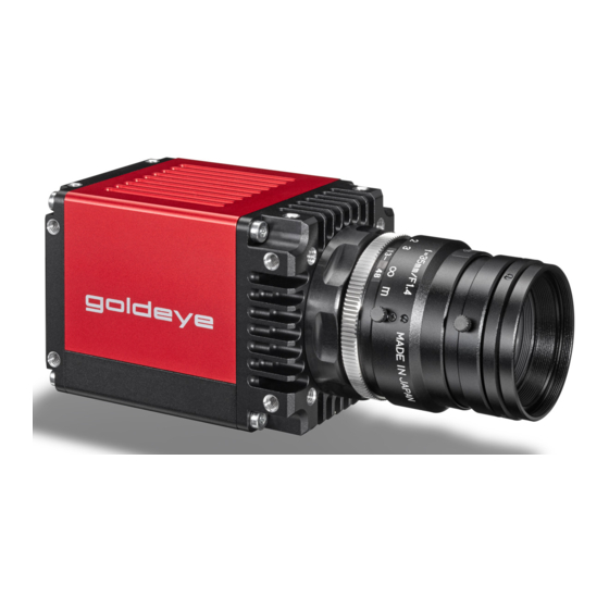
Allied Vision Goldeye G Series Quick Start Manual
Hide thumbs
Also See for Goldeye G Series:
- Technical manual (234 pages) ,
- Technical manual (254 pages)
Table of Contents
Advertisement
Quick Links
Download this manual
See also:
Technical Manual
Advertisement
Table of Contents

Summary of Contents for Allied Vision Goldeye G Series
- Page 1 Goldeye G V1.1.0 Quickstart Guide 2018-Jun-20 Part ID: 10683010...
- Page 2 Validity This QuickStart Guide is valid for the following Goldeye G models: Model Order codes Sensor Goldeye G-008: 4068xxx InGaAs FPA 320 x 256 All standard and customized models 6068xxx Goldeye G-032: 4068xxx InGaAs FPA 636 x 508 All standard and customized models 6068xxx Goldeye G-033: 4068xxx...
-
Page 3: Shipping Contents
Shipping contents • Goldeye G camera • Goldeye G Cameras Quickstart Guide What else do you need? Document/Information Document Goldeye G/CL https://www.alliedvision.com/en/support/technical- Technical Manual documentation/goldeye-gcl-documentation.html Goldeye G/CL Features https://www.alliedvision.com/en/support/technical- reference documentation/goldeye-gcl-documentation.html Trigger- and power cables See the Accessories table on page 4. Software Reference Vimba... - Page 4 Accessories Note for the accessories listed below it is assumed that a suitable power supply is available. I/O cable with Hirose 12-pin connector (not for models with Cool housing). Length 2 m 10 m Order code 2814 2815 2817 2818 Power cable with Hirose 4-pin connector (for Cool models only).
-
Page 5: Contacting Allied Vision
Contacting Allied Vision Website To directly contact Allied Vision with any enquiry, go to: https://www.alliedvision.com/en/meta-header/contact To find an Allied Vision office or distribution partner, go to: https://www.alliedvision.com/en/about-us/where-we-are Phone and E-mail For all camera-related queries contact us at support@alliedvision.com For all general inquiries, contact us at info@alliedvision.com... -
Page 6: Compliance, Safety, And Intended Use
Compliance, safety, and intended use For customers in Europe Allied Vision has demonstrated the fulfillment of the requirements relating to the Goldeye G/CL camera family. • Directive 2014/30/EU (Electromagnetic compatibility) • Directive 2011/65/EU, incl. amendment 2015/863/EU (RoHS) Directive 2012/19/EU ... - Page 7 against harmful interference in a residential installation. This equipment generates, uses and can radiate radio frequency energy and, if not installed and used in accordance with the instructions, may cause harmful interference to radio communications. However, there is no guarantee that interference will not occur in a particular installation.
- Page 8 Avoid electromagnetic interferences For all power and interface connections, use shielded cables only. Please use cables recommended by Allied Vision. Camera applications and intended use General use • The user is responsible for operating the camera within the specifications defined in the user guide, and within appropriate environmental conditions and technical prerequisites, to ensure trouble-free camera operation.
- Page 9 Usage of the software is solely the responsibility of the user. • The camera must not be opened. For all repair tasks, contact Allied Vision or one of Allied Vision's authorized representatives. • Observe the intended use. The camera must only be used for purposes that are in conformity with the stated intended use.
-
Page 10: Overview Of Installation
Overview of installation Complete the steps listed below to successfully install your Goldeye G camera. 1. Install Gigabit Ethernet network card and configure network card. 2. Install Vimba SDK plus corresponding viewers. 3. Connect camera to PC or laptop and ensure that the camera is powered. 4. - Page 11 Installing a Gigabit Ethernet network card If your host computer has an available Ethernet interface, this can be used with Allied Vision GigE cameras. We recommend that your camera system uses a dedicated Ethernet interface not shared with Internet or local area networks. If...
- Page 12 If a DHCP server is present, this will define the address. To connect to the camera, configure the following settings. • IP Address: 169.254.100.1 • Subnet mask: 255.255.0.0 • Default gateway: blank Optimizing Ethernet adapter Edit the Ethernet adapter driver properties according to the values listed below. Properties Values Packet size...
-
Page 13: Powering Up The Camera
For Cool models, use the 4-pin Hirose connector. A steady flashing of the Ethernet status LEDs indicates the boot phase. A camera power adapter for the Goldeye G series is available from Allied Vision. -
Page 14: Connecting To The Host Computer
Connecting to the host computer To connect the camera to the host computer, use a Category 5e cable or higher. Launch the applications 1. Power up the camera and wait until the Ethernet Status LEDs stop blinking. This indicates booting has been finished. 2. -
Page 16: Copyright And Trademarks
All content is subject to change without notice. All trademarks, logos, and brands cited in this document are property and/or copyright material of their respective owners. Use of these trademarks, logos, and brands does not imply endorsement. Copyright © 2018 Allied Vision GmbH. All rights reserved.


Need help?
Do you have a question about the Goldeye G Series and is the answer not in the manual?
Questions and answers